EP2048774A2 - Système électrique rotatif avec enroulements de stator multiphase connectés en étoile - Google Patents
Système électrique rotatif avec enroulements de stator multiphase connectés en étoile Download PDFInfo
- Publication number
- EP2048774A2 EP2048774A2 EP08017733A EP08017733A EP2048774A2 EP 2048774 A2 EP2048774 A2 EP 2048774A2 EP 08017733 A EP08017733 A EP 08017733A EP 08017733 A EP08017733 A EP 08017733A EP 2048774 A2 EP2048774 A2 EP 2048774A2
- Authority
- EP
- European Patent Office
- Prior art keywords
- stator windings
- multiphase
- rotary electric
- switch
- switching elements
- Prior art date
- Legal status (The legal status is an assumption and is not a legal conclusion. Google has not performed a legal analysis and makes no representation as to the accuracy of the status listed.)
- Granted
Links
Images



Classifications
-
- H—ELECTRICITY
- H02—GENERATION; CONVERSION OR DISTRIBUTION OF ELECTRIC POWER
- H02M—APPARATUS FOR CONVERSION BETWEEN AC AND AC, BETWEEN AC AND DC, OR BETWEEN DC AND DC, AND FOR USE WITH MAINS OR SIMILAR POWER SUPPLY SYSTEMS; CONVERSION OF DC OR AC INPUT POWER INTO SURGE OUTPUT POWER; CONTROL OR REGULATION THEREOF
- H02M1/00—Details of apparatus for conversion
- H02M1/32—Means for protecting converters other than automatic disconnection
-
- B—PERFORMING OPERATIONS; TRANSPORTING
- B60—VEHICLES IN GENERAL
- B60L—PROPULSION OF ELECTRICALLY-PROPELLED VEHICLES; SUPPLYING ELECTRIC POWER FOR AUXILIARY EQUIPMENT OF ELECTRICALLY-PROPELLED VEHICLES; ELECTRODYNAMIC BRAKE SYSTEMS FOR VEHICLES IN GENERAL; MAGNETIC SUSPENSION OR LEVITATION FOR VEHICLES; MONITORING OPERATING VARIABLES OF ELECTRICALLY-PROPELLED VEHICLES; ELECTRIC SAFETY DEVICES FOR ELECTRICALLY-PROPELLED VEHICLES
- B60L3/00—Electric devices on electrically-propelled vehicles for safety purposes; Monitoring operating variables, e.g. speed, deceleration or energy consumption
- B60L3/0023—Detecting, eliminating, remedying or compensating for drive train abnormalities, e.g. failures within the drive train
- B60L3/003—Detecting, eliminating, remedying or compensating for drive train abnormalities, e.g. failures within the drive train relating to inverters
-
- H—ELECTRICITY
- H02—GENERATION; CONVERSION OR DISTRIBUTION OF ELECTRIC POWER
- H02P—CONTROL OR REGULATION OF ELECTRIC MOTORS, ELECTRIC GENERATORS OR DYNAMO-ELECTRIC CONVERTERS; CONTROLLING TRANSFORMERS, REACTORS OR CHOKE COILS
- H02P29/00—Arrangements for regulating or controlling electric motors, appropriate for both AC and DC motors
- H02P29/02—Providing protection against overload without automatic interruption of supply
- H02P29/032—Preventing damage to the motor, e.g. setting individual current limits for different drive conditions
-
- H—ELECTRICITY
- H02—GENERATION; CONVERSION OR DISTRIBUTION OF ELECTRIC POWER
- H02P—CONTROL OR REGULATION OF ELECTRIC MOTORS, ELECTRIC GENERATORS OR DYNAMO-ELECTRIC CONVERTERS; CONTROLLING TRANSFORMERS, REACTORS OR CHOKE COILS
- H02P2209/00—Indexing scheme relating to controlling arrangements characterised by the waveform of the supplied voltage or current
- H02P2209/01—Motors with neutral point connected to the power supply
-
- Y—GENERAL TAGGING OF NEW TECHNOLOGICAL DEVELOPMENTS; GENERAL TAGGING OF CROSS-SECTIONAL TECHNOLOGIES SPANNING OVER SEVERAL SECTIONS OF THE IPC; TECHNICAL SUBJECTS COVERED BY FORMER USPC CROSS-REFERENCE ART COLLECTIONS [XRACs] AND DIGESTS
- Y02—TECHNOLOGIES OR APPLICATIONS FOR MITIGATION OR ADAPTATION AGAINST CLIMATE CHANGE
- Y02T—CLIMATE CHANGE MITIGATION TECHNOLOGIES RELATED TO TRANSPORTATION
- Y02T10/00—Road transport of goods or passengers
- Y02T10/60—Other road transportation technologies with climate change mitigation effect
- Y02T10/64—Electric machine technologies in electromobility
Definitions
- the present invention relates to a rotary electric system equipped with a multiphase inverter including a pair of high-side and low-side switching elements for each phase of a multiphase motor, and more particularly to such a rotary electric system designed to address a fault, such as an open fault, of at least one switching element constituting the inverter.
- Alternating current (AC) motor systems are used widely for: motor vehicles as their electric power steering systems, hybrid vehicles as their drive systems, and electric compressors as their drive systems.
- Such an AC motor system is designed to drive a multiphase motor having a multiphase stator coil by a multiphase inverter; this multiphase stator coil consists of star-connected multiphase stator windings.
- power semiconductor switching elements such as IGBTs and/or MOSFETs
- IGBTs and/or MOSFETs are normally used.
- IGBTs and/or MOSFETs are normally used.
- Japanese Patent Application Publication No. 2007-099066 discloses an electric power steering system for addressing open faults of power semiconductor switching elements constituting a three-phase inverter for driving a star-connected three-phase brushless motor.
- the electric power steering system is provided with a first relay connected in series between a U-phase stator winding and a neutral point of the star-connected three-phase stator windings and a second relay connected in series between a V-phase stator winding and the neutral point of the star-connected three-phase stator windings.
- the electric power steering system is also provided with a third relay connected in series between a W-phase stator winding and the neutral point of the star-connected three-phase stator windings, and a fourth relay connected between the neutral point of the star-connected three-phase stator windings and a neutral-point driver.
- the two-phase stator winding driving method may increase variations in the rotation of the three-phase brushless motor and those in the torque created thereby, as compared with driving of the three-phase stator windings of the three-phase brushless motor. This results in reducing the drivability of the three-phase brushless motor.
- the electric power steering system disclosed in the Patent Application Publication may have a complicated circuit structure that individually turns off a power semiconductor switching element for each phase stator winding and turns on the fourth relay. This may increase the electric power steering system in size and/or manufacturing cost, resulting in reducing the installability of the electric power steering system in various vehicles and machines.
- an object of an aspect of the present invention is to provide rotary electric systems each provided with a multiphase inverter including a pair of high-side and low-side switching elements for each phase of a multiphase motor; these systems are each capable of reliably addressing faults of the high-side switching element or low-side switching element with its circuit structure being uncomplicated.
- a rotary electric system includes a rotary electric machine provided with a rotor and star-connected multiphase stator windings with a neutral point.
- the rotary electric machine works to rotate the rotor when the multiphase stator windings are energized.
- the rotary electric system includes a direct current power source having a high-side electrode and a low-side electrode, and a multiphase inverter.
- the multiphase inverter includes a high-side switching element and a low-side switching element per phase of the multiphase stator windings. The high-side and low-side switching elements are connected with each other in series.
- the multiphase inverter works to energize the multiphase stator windings based on power supplied from the direct current power source when driven.
- the rotary electric system includes a switch member including at least one of a first switch and a second switch.
- the first switch is connected between the neutral point of the multiphase stator windings and the high-side electrode.
- the second switch is connected between the neutral point of the multiphase stator windings and the low-side electrode.
- the rotary electric system includes a controller connected with the high-side and low-side switching elements per phase of the multiphase stator windings and with the switch member and working to turn the switch member off and on to thereby switch control of the multiphase inverter between full-wave driving mode and half-wave driving mode.
- the full-wave driving mode allows the controller to drive all of the high-side and low-side switching elements per phase of the multiphase stator windings.
- the half-wave driving mode allows the controller to drive any one of the high-side switching element and the low-side switching element per phase of the multiphase stator windings.
- the rotary electric system allows selectively control of the multiphase inverter in the full-wave driving mode or in the half-wave driving mode.
- the controller works to turn the switch member on to thereby switch control of the multiphase inverter from the full-wave driving mode to the half-wave driving mode via the low-side switching element per phase without using the high-side switching element per phase.
- the controller drives any one of the high-side switching element and the low-side switching element per phase of the multiphase stator windings.
- the controller drives any one of the high-side switching element and the low-side switching element per phase of the multiphase stator windings.
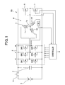
- a rotary electric system RS according to an embodiment of the present invention.
- the rotary electric system RS includes a three-phase motor M equipped with an annular rotor (not shown) and a star-connected three-phase stator coil 1.
- the annular rotor is provided at its circumferential portion with at least one north pole (N) and at least one south pole (S).
- the rotary electric system RS also includes a three-phase inverter 2 for supplying three-phase AC power to the three-phase stator coil 1, and a smoothing capacitor 3 operative to smooth an input DC voltage to be inputted to the inverter 2.
- the stator coil 1 consists of a stator core (not shown) disposed around the outer periphery of the rotor such that the inner periphery of the stator core is opposite to the outer periphery of the rotor with a predetermined air gap.
- the stator coil 1 also consists of a U-phase stator winding 11, a V-phase stator winding 12, and a W-phase stator winding 13.
- the stator core for example has a plurality of slots. The slots are for example formed through the stator core and are circumferentially arranged at given intervals.
- the three-phase stator windings 11, 12, and 13 are wound in the slots such that the U-, V-, and W-phase stator windings 11, 12, and 13 are shifted by an electric angle of, for example, 2 ⁇ /3 radian in phase from each other.
- One ends of the U-, V-, and W-phase stator windings 11, 12, and 13 are connected to each other in star configuration to constitute a neutral point 1a.
- the rotary electric machine RS also includes a battery 5 for supplying the DC voltage to the inverter 2 via the smoothing capacitor 3, and a relay 4 for opening or closing an electrical connection between the inverter 2 and the battery 5.
- the rotary electric machine RS further includes a first switch 6 and a second switch 7.
- the first switch 6 works to open or close an electrical connection between the neutral point 1a of the stator coil 1 and a high-side terminal of the inverter 2.
- the second switch 7 works to open or close the neutral point 1a of the stator coil 1 and a low-side terminal of the inverter 2.
- the rotary electric machine RS includes a controller 8 for controlling the inverter 2, the first switch 6, the second switch 7, and the relay 4.
- the inverter 2 is composed of a first pair (bridge arm) of series-connected switching elements SW1 and SW2, a second pair of series-connected switching elements SW3 and SW4, and a third pair of series-connected switching elements SW5 and SW6.
- the inverter 2 is also composed of flywheel diodes (not shown) connected in antiparallel with the switching elements SW1, SW2, SW3, SW4, SW5, and SW6, respectively.
- IGBTs Insulated Gate Bipolar Transistors
- power MOSFETs Insulated Gate Bipolar Transistors
- the intrinsic diodes of the power MOSFETs can be used in place of the flywheel diodes.
- each of the switching elements SW1 to SW6 a MOSFET device with current-sense terminals is used.
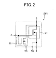
- Fig. 2 schematically illustrates the switching element SW1 to which the MOSFET device with a current-sense terminal is used.
- Each of the remaining switching elements SW2 to SW6 are identical in configuration to the switching element SW1.
- the switching element SW1 includes a pair of NMOSFETs 21 and 22.
- a NMOSFET chip corresponding to the NMOSFET 22 is prepared, and a current-sensing MOSFET 21 is integrated on the NMOSFET chip to thereby easily produce the switching element SW1 with the current-sense terminal.
- the drains D and gates G of the NMOSFETs 21 and 22 are in common with each other.
- the common drain D and common gate G serve as the drain and gate of the switching element SW1.
- the common gate G of the switching element SW1 serves as a control terminal thereof.
- Reference character MS represents the source of the NMOSFET 22, and reference character S represents the source of the NMOSFET 21.
- Reference character KS represents a sense-terminal of the switching elements SW1; this sense-terminal is connected to the controller 8.
- the controller 8 monitors the value of the branch current flowing out of the sense-terminal KS to thereby measure the value of the main current flowing through the switching element SW1.
- each of the switching elements SW1 to SW6 can be designed as a normal MOSFET or IGBT, and an external current-sense circuit can be provided for each of the switching elements SW1 to SW6; this external current-sense circuit works to measure a value of a current flowing through each of the switching elements SW1 to SW6.
- each of the flywheel diodes is connected with the drain of a corresponding one of the switching elements, and the anode thereof is connected with the source of a corresponding one of the switching elements.
- the first to third bridge arms of switching elements SW1 to SW6 are parallely connected with each other in bridge configuration.
- a connecting point through which the switching elements SW1 and SW2 of the first pair are connected with each other in series is connected with an output lead extending from the output end (other end) of the U-phase stator winding 11.
- a connecting point through which the switching elements SW3 and SW4 of the second pair are connected with each other in series is connected with an output lead extending from the output end (other end) of the V-phase stator winding 12.
- a connecting point through which the switching elements SW5 and SW6 of the third pair are connected with each other in series is connected with an output lead extending from the output end (other end) of the W-phase stator winding 13.
- each of the first, second, and third bridge arms corresponding to the high-side DC input terminal of the inverter 2 is connected with a high-side electrode of the battery 5 and with one electrode of the capacitor 3.
- the other end of each of the first, second, and third bridge arms corresponding to the low-side DC input terminal of the inverter 2 is connected with a low-side electrode of the battery 4 and with the other electrode of the capacitor 3.
- the controller 8 is connected with the control terminal of each of the switching elements SW1 to SW6, with a pole position sensor 32 for measuring a rotational pole position (angular pole position) of the rotor, and with a power source (not shown).
- the pole position sensor 32 is normally designed to use a resolver or a circuit composed of a magnet and a hall IC.
- the controller 8 can be designed to sensorlessly measure an angular pole position of the rotor with the use of, for example, the zero crossing of an induced voltage in one of the three-phase stator windings 11, 12, and 13 based on the zero crossing of the amount of change in a phase current to flow through the one of the three-phase stator windings.
- the zero crossing of an induced voltage in one of the three-phase stator windings represents an angular pole position of the rotor.
- the controller 8 is integrated with a microcomputer and its peripheries including a driver for driving each switching element and relay.
- the controller 8 works to operate in full-wave driving mode including well-known 120-degree modulation, 180-degree modulation, or PWM sine-wave modulation to thereby individually drive on and off the switching elements SW1, SW2, SW3, SW4, SW5, and SW6 based on the measured angular pole position of the rotor.
- the full-wave driving mode is to individually drive on and off the switching elements SW1, SW2, SW3, SW4, SW5, and SW6 (both of the upper-arm switching elements SW1, SW3, SW5 and the lower-arm switching elements SW2, SW4, and SW6).
- each of the three-phase stator windings 11, 12, and 13 is energized in positive phase during rotation of the rotor by 120 electric degrees, and after rotation of the rotor by 60 electric degrees, each of the three-phase stator windings 11, 12, and 13 is energized in negative phase for rotation of the rotor by 120 electric degrees.
- each of the three-phase stator windings 11, 12, and 13 is energized in positive phase during rotation of the rotor by 180 electric degrees, and continuously energized in negative phase during rotation of the rotor by 180 electric degrees.
- the circuit structure of the rotary electric machine RS is specifically equipped with the first switch 6 that can short-circuit the neutral point 1a to the high-side terminal of the inverter 2; this first switch 6 therefore serves as high-side switching element short-circuiting switch.
- the circuit structure of the rotary electric machine RS is also specifically equipped with the second switch 7 that can short-circuit the neutral point 1a to the low-side terminal of the inverter; this second switch 7 serves as low-side switching element short-circuiting switch.
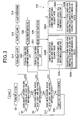
- the controller 8 When energized by the power source, the controller 8 turns the relay 4 on, resulting in that a DC voltage is applied from the battery 5 to the inverter 2 via the relay 4 in step S2.
- controller 8 determines whether short-circuit failure occurs in at least one of the switching elements SW1 to SW6 in step S6.
- step S6 the controller 8 individually supplies, in time sequential manner, a gate signal to the gate of each of the switching elements SW1 to SW6 to thereby turn it off.
- the controller 8 receives a value of a branch current flowing out of the sense-terminal KS of the corresponding one of the switching elements SW1 to SW6.
- the controller 8 measures a value of a main current flowing through the corresponding one of the switching elements SW1 to SW6 based on the received value of the branch current.
- step S6 the controller 8 compares the measured value of the main current flowing through the corresponding one of the switching elements SW1 to SW6 with a preset threshold value. Based on a result of the comparison, the controller 8 determines whether the measured value of the main current flowing through the corresponding one of the switching elements SW1 to SW6 exceeds the preset threshold value.
- the controller 8 determines that short-circuit failure occurs in the corresponding one of the switching elements SW1 to SW6 in step S6.
- step S6 Upon determining that short-circuit failure occurs in at least one of the switching elements SW1 to SW6 (the determination in step S6 is YES), the controller 8 turns the relay 4 off in step S14, visibly or audibly informs an operator for the rotary electric machine RS of information indicative of at least one switching element being short-circuited in step S16. Thereafter, the controller 8 halts operations of the rotary electric system RS in step S 18.
- step S6 Upon determining that short-circuit failure does not occur in any one of the switching elements SW1 to SW6 (the determination in step S6 is NO), the controller 8 proceeds to step S8.
- step S8 the controller 8 determines whether open-circuit failure (disconnection fault) occurs in each of the upper-arm switching elements SW1, SW3, and SW5.
- step S8 the controller 8 individually supplies, in time sequential manner, a gate signal to the gate of each of the upper-arm switching elements SW1, SW3, and SW5 to thereby turn it on.
- the controller 8 receives a value of a branch current flowing out of the sense-terminal KS of the corresponding one of the upper-arm switching elements SW1, SW3, and SW5.
- the controller 8 measures a value of a main current flowing through the corresponding one of the upper-arm switching elements SW1, SW3, and SW5 based on the received value of the branch current.
- step S8 the controller 8 compares the measured value of the main current flowing through the corresponding one of the upper-arm switching elements SW1, SW3, and SW5 with a preset threshold value. Based on a result of the comparison, the controller 8 determines whether the measured value of the main current flowing through the corresponding one of the upper-arm switching elements SW 1, SW3, and SW5 exceeds the preset threshold value.
- the controller 8 determines that open-circuit fault occurs in the at least one of the upper-arm switching elements SW1, SW3, and SW5 in step S8.
- step S8 Upon determining that open-circuit failure occurs in at least one of the upper-arm switching elements SW1, SW3, and SW5, (the determination in step S8 is YES), the controller 8 turns each of the upper-arm switching elements SW1, SW3, and SW5 off in step S20, and turns the first switch 6 on in step S22, proceeding to step S28A.
- step S28A the controller 8 carries out control of the inverter 2 in lower-arm half-wave driving mode. Specifically, in the lower-arm switching-element driving mode, the controller 8 turns each of the upper-arm switching elements SW1, SW3, SW5 off in step S28a. In step S28b, the controller 8 turns the first switch 6 on, and sequentially turns each of the individual the lower-arm switching elements SW2, SW4, and SW6 on and off during the first switch 6 being on state. This allows the three-phase motor M to operate in three-phase half-wave driving mode.
- the controller 8 individually drives on and off the lower-arm switching elements SW2, SW4, and SW6 based on the measured angular pole position of the rotor. This allows a substantially square-wave voltage to be applied to each of the three-phase stator windings 11, 12, and 13 of the stator coil 1.
- a drive current based on the square-waved voltage supplied from the battery 5 is supplied to flow via the first switch 6, the neutral point N, the U-phase stator winding 11, and the lower-arm switching element SW2.
- the controller 8 is programmed to adjust an on period (on duration) of each of the lower-arm switching elements SW2, SW4, and SW6 to be within a range between 120 electric degrees and 180 electric degrees.
- This adjustment method has been well-known in the art to which the present invention belongs, and therefore, detailed descriptions for the adjustment method are omitted.
- step S8 the controller 8 proceeds to step S10.
- step S10 the controller 8 determines whether open-circuit failure (disconnection fault) occurs in each of the lower-arm switching elements SW2, SW4, and SW6.
- step S 10 the controller 8 individually supplies, in time sequential manner, a gate signal to the gate of each of the lower-arm switching elements SW2, SW4, and SW6 to thereby turn it on.
- the controller 8 receives a value of a branch current flowing out of the sense-terminal KS of the corresponding one of the lower-arm switching elements SW2, SW4, and SW6.
- the controller 8 measures a value of a main current flowing through the corresponding one of the lower-arm switching elements SW2, SW4, and SW6 based on the received value of the branch current.
- step S10 the controller 8 compares the measured value of the main current flowing through the corresponding one of the lower-arm switching elements SW2, SW4, and SW6 with a preset threshold value. Based on a result of the comparison, the controller 8 determines whether the measured value of the main current flowing through the corresponding one of the lower-arm switching elements SW2, SW4, and SW6 exceeds the preset threshold value.
- the controller 8 determines that open-circuit fault occurs in the at least one of the lower-arm switching elements SW2, SW4, and SW6 in step S10.
- step S10 Upon determining that open-circuit failure occurs in at least one of the lower-arm switching elements SW2, SW4, and SW6, (the determination in step S10 is YES), the controller 8 turns each of the lower-arm switching elements SW2, SW4, and SW6 off in step S24, and turns the second switch 7 on in step S26, proceeding to step S28B.
- step S28B the controller 8 carries out control of the inverter 2 in upper-arm half-wave driving mode. Specifically, in the upper-arm switching-element driving mode, the controller 8 turns each of the lower-arm switching elements SW2, SW4, SW6 off in step S28c. In step S28d, the controller 8 turns the second switch 7 on, and sequentially turns each of the individual the uppwer-arm switching elements SW1, SW3, and SW5 on and off during the second switch 7 being on state. This allows the three-phase motor M to operate in three-phase half-wave driving mode.
- the controller 8 individually drives on and off the upper-arm switching elements SW1, SW3, and SW5 based on the measured angular pole position of the rotor. This allows a square-waved voltage to be applied to each of the three-phase stator windings 11, 12, and 13 of the stator coil 1.
- the controller 8 is programmed to adjust an on period (on duration) of each of the upper-arm switching elements SW1, SW3, and SW5 to be within a range between 120 electric degrees and 180 electric degrees.
- This adjustment method has been well-known in the art to which the present invention belongs, and therefore, detailed descriptions for the adjustment method are omitted.
- the controller 8 carries out control of the inverter 2 in the full-wave driving mode with the use of vector control.
- the vector control is for example to:
- the rotary electric system RS As described above, the rotary electric system RS according to the embodiment is provided with:
- the rotary electric system RS is designed to turn each of the first and second switches 6 and 7 individually on or off to thereby switch control of the inverter 2 between the full-wave driving mode and the half-wave driving mode.
- the rotary electric system RS when detecting an open fault occurring in at least one of the high-side switching elements SW1, SW3, and SW5, the rotary electric system RS is designed to turn:
- the rotary electric system RS when detecting an open fault occurring in at least one of the low-side switching elements SW2, SW4, and SW6, the rotary electric system RS is designed to turn:
- the rotary electric system RS drives the three-phase stator windings 11, 12, and 13 to thereby continuously rotate the three-phase motor M even though at least one switching element of the inverter 2 fails without using switches for respective three-phase stator windings 11, 12, and 13 of the stator coil 1.
- the rotary electric system RS achieves an effect of reliably addressing a fault occurring in at least one switching element of the inverter 2 with the circuit structure of the rotary electric system RS being complicated.
- the controller 8 sequentially drives the upper-arm three-phase switching elements or the lower-arm three-phase switching elements.
- the controller 8 is designed to apply a substantially square-wave voltage to each of the three-phase stator windings 11, 12, and 13 during an on period (on duration) of a corresponding one of the higher or lower-arm switching elements; this on period is determined within a range from 120 electric degrees to 180 electric degrees of rotation of the rotor.
- the peak-to-peak amplitude of a pulse voltage to be applied to each of the high-side or low-side switching elements is reduced as compared with that of a pulse voltage to be applied to each of the switching elements in the full-wave driving mode.
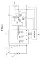
- a rotary electric system RS1 In order to adjust a current to be supplied to each phase stator winding of the stator coil 1 to a required value, a rotary electric system RS1 according to the embodiment can use constant-current feedback control in the half-wave driving mode. Like parts between the rotary electric systems RS and RS1 according to the embodiment and the first modification, to which like reference characters are assigned, are omitted or simplified in description.
- the rotary electric system RS1 is equipped with current sensors 31 for measuring phase currents to be supplied to the respective phase stator windings 11, 12, and 13.
- Each of the current sensors 31 is designed to use, for example, a hall IC.
- the rotary electric system RS1 is also equipped with a controller 8A.
- the controller 8A is connected with a request torque input device (not shown) for externally inputting, to the controller 8A, a commanded torque (request torque) for the rotary electric system RS 1 by an operator.
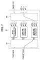
- the controller 8A includes functional modules 33, Su, Sv, Sw, 34, and 35 illustrated in Fig. 6 .
- the functional modules 33, Su, Sv, Sw, 34, and 35 can be implemented in the controller 8A by software modules or hardware modules.
- Reference character 33 represents a three-phase command current calculator 33 including current maps 332, 333, and 334 (see Fig. 7 ).
- the three-phase command current calculator 33 is operative to calculate, based on the angular pole position ⁇ measured by the pole position sensor 32, a value of the command torque, and the current maps 332, 333, and 334, three-phase command current values Iu*, Iv*, and Iw* to be supplied to the respective three-phase stator windings 11, 12, and 13.
- the current map 332 serves as a normal vector-control current map including data indicative of a relationship between a variable of each of three-phase command current values Iu1*, Iv1*, and Iw1* determined to be required in normal state, a variable of the command torque, and a variable of the angular pole position ⁇ .
- the current map 333 serves as a lower-arm open-failed vector-control current map including data indicative of a relationship between a variable of each of three-phase command current values Iu2*, Iv2*, and Iw2* determined to be required in lower-arm open-failed state, a variable of the command torque, and a variable of the angular pole position ⁇ .
- the current map 334 serves as an upper-arm open-failed vector-control current map including data indicative of a relationship between a variable of each of three-phase command current values Iu3*, Iv3*, and Iw3* determined to be required in upper-arm open-failed state, a variable of the command torque, and a variable of the angular pole position ⁇ .
- the three-phase command current calculator 33 also includes a map selector 331 and a command current value selector 335.
- step S10 When the determination in step S10 is NO, the controller 8A sets a code (flag) "0" representing "normal mode” as a failure mode, and when the determination in step S10 is YES, the controller 8A sets a code “1" representing "low-side open-fault mode” as the failure mode. When the determination in step S8 is YES, the controller 8A sets a code "2" representing "high-side open-fault mode” as the failure mode.
- step S12 because the code "0" represents the normal mode as the failure mode, the map selector 331 selects the normal vector-control current map 332. Then, the command current value selector 335 selects, in the map 332, a value of the three-phase command current values Iu1*, Iv1*, and Iw1* corresponding to the angular pole position ⁇ measured by the pole position sensor 32 and the value of the command torque. Thus, the command current value selector 335 outputs the selected value of the three-phase command current values Iu1*, Iv1*, and Iw1* as the three-phase command current values Iu*, Iv*, and Iw*.
- step S24 because the code "1" represents the low-side open-fault mode as the failure mode, the map selector 331 selects the lower-arm open-failed vector-control current map 333. Then, the command current value selector 335 selects, in the map 333, a value of the three-phase command current values Iu2*, Iv2*, and Iw2* corresponding to the angular pole position ⁇ measured by the pole position sensor 32 and the value of the command torque. Thus, the command current value selector 335 outputs the selected value of the three-phase command current values Iu2*. Iv2*, and Iw2* as the three-phase command current values Iu*, Iv*, and Iw*.
- step S20 because the code "2" represents the high-side open-fault mode as the failure mode, the map selector 331 selects the upper-arm open-failed vector-control current map 334. Then, the command current value selector 335 selects, in the map 334, a value of the three-phase command current values Iu3*, Iv3*, and Iw3* corresponding to the angular pole position ⁇ measured by the pole position sensor 32 and the value of the command torque. Thus, the command current value selector 335 outputs the selected value of the three-phase command current values Iu3*, Iv3*, and Iw3* as the three-phase command current values Iu*, Iv*, and Iw*.
- Reference characters Su, Sv, Sw represent subtractors.
- the subtractor Su works to calculate the difference between the U-phase command current value Iu* and a U-phase current value Iu actually measured by the corresponding current sensor 31.
- the subtractor Sv works to calculate the difference between the V-phase command current value Iv* and a V-phase current value Iv actually measured by the corresponding current sensor 31, and the subtractor Sw works to calculate the difference between the W-phase command current value Iw* and a W-phase current value Iw actually measured by the corresponding current sensor 31.
- Reference character 34 represents a PI (Proportional Integral) controller.
- the PI controller 34 works to calculate three-phase voltage command values Vu*, Vv*, and Vw* based on the calculated U-, V-, and W-phase current differences in accordance with a PI feedback control algorithm (PI algorithm).
- PI algorithm PI feedback control algorithm
- the PI controller 34 works to calculate each of U-, V-, and W-phase voltage command values Vu*, Vv*, and Vw* that allows the calculated U-, V-, and W-phase current differences to become zero.
- Reference character 35 represents a converter.
- the converter 35 works to convert the calculated three-phase voltage command values Vu*, Vv*, and Vw* into duty cycles for respective three-phase switching elements of the inverter 2. Thereafter, the converter 35 works to generate three-phase pulse signals Gu*, Gv*, and Gw* based on the converted duty cycles for the respective three-phase switching elements of the inverter 2. In other words, the converter 35 works to generate the three-phase pulse signals Gu*, Gv*, and Gw* each, with a modulated pulse width with a corresponding one of the converted duty cycles for the respective three-phase switching elements of the inverter 2.
- the converter 35 also works to apply the three-phase pulse signals Gu*, Gv*, and Gw* to the respective three-phase switching elements of the inverter 2.
- step S12 the converter 35 applies the U-phase pulse signal Gu* to each of the switching elements SW1 and SW2, the V-phase pulse signal Gv* to each of the switching elements SW3 and SW4, and the W-phase pulse signal Gw* to each of the switching elements SW5 and SW6.
- step S22 the converter 35 applies the U-phase pulse signal Gu* to the switching element SW2, the V-phase pulse signal Gv* to the switching element SW4, and the W-phase pulse signal Gw* to the switching element SW6.
- step S26 the converter 35 applies the U-phase pulse signal Gu* to the switching element SW1, the V-phase pulse signal Gv* to the switching element SW3, and the W-phase pulse signal Gw* to the switching element SW5.
- Fig. 8 schematically illustrates a waveform of each of the three-phase currents Iu, Iv, and Iw to be supplied to the respective three-phase stator windings 11, 12, and 13 and that of instantaneous torque to be created by the three-phase motor M when the inverter 2 is controlled in the upper-arm half-wave driving mode.
- Fig. 8 demonstrates that each of the three-phase currents Iu, Iv, and Iw each with a trapezoidal shape is supplied to a corresponding one of the three-phase stator windings 11, 12, and 13.
- the controller 8A works to carry out the constant-current feedback control to thereby set the sum of the U-phase current command value Iu* and the V-phase current command value Iv* to a constant value. This allows the sum of the U-phase current value Iu and the V-phase current value Iv to become the constant value, making it possible to locally minimize torque ripples appearing in the three-phase motor M.
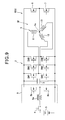
- Fig. 9 schematically illustrates the circuit structure of an example of a rotary electric system RS2 according to a second modification of the embodiment in which the controller 8 and the pole position sensor 32 are omitted in illustration.
- the rotary electric system RS2 includes a DC to DC converter 9, that is, a PAM (Pulse Amplitude Modulation) circuit.
- the DC to DC converter 9 consists of, for example, a choke coil 9a and a pair of transistors 9b.
- the DC to DC converter 9 is provided between the relay 4 and the smoothing capacitor 3.
- the DC to DC converter 9 is designed as a boost chopper.
- the DC to DC converter 9 works to control its duty ratio to thereby boost the DC voltage of the battery 5 to a required level.
- At least one of the first switch 6 and the second switch 7 can be designed as a relay.
- the rotary electric systems RS, RS1, and RS2 can be applied to: motor vehicles as their electric power steering systems for increasing steering force to be applied to turning of a steering, hybrid vehicles as their drive systems, electric compressors as their drive systems, radiators as their fan drive systems, and intake and exhaust valve control systems for engines as their drive systems.
- each of the first and second switches 6 and 7 can be made up of a bidirectionally conductive semiconductor device.
- the semiconductor switch has an operating speed higher than alternative non-semiconductor switches, and therefore, the on and off speed of each of the first and second switches 6 and 7 can be increases as compared with the alternative non-semiconductor switches.
- one of the rotary electric systems RS, RS1, and RS2 is installed in a drive motor for driving drive wheels of a motor vehicle.
- energy regenerated by the operations of the brake system is designed to rotate the three-phase motor M. This generates power, and the generated power can be transferred via the bidirectionally conductive semiconductor switch to the battery 5 to be charged therein.
- the present invention is applied to the rotary electric systems each with the star-connected three-phase motor M, but the present invention is not limited to the structures. Specifically, the present invention can be applied to rotary electric machines each with star-connected multiphase rotary electric machine, such as a star-connected five-phase rotary electric machine.
- the rotary electric systems can be designed to control various types of rotary electric machines, such as power generators.
Landscapes
- Engineering & Computer Science (AREA)
- Power Engineering (AREA)
- Life Sciences & Earth Sciences (AREA)
- Sustainable Development (AREA)
- Sustainable Energy (AREA)
- Transportation (AREA)
- Mechanical Engineering (AREA)
- Control Of Ac Motors In General (AREA)
- Control Of Electric Motors In General (AREA)
- Inverter Devices (AREA)
Applications Claiming Priority (1)
| Application Number | Priority Date | Filing Date | Title |
|---|---|---|---|
| JP2007264743A JP4609474B2 (ja) | 2007-10-10 | 2007-10-10 | 回転電機装置 |
Publications (3)
| Publication Number | Publication Date |
|---|---|
| EP2048774A2 true EP2048774A2 (fr) | 2009-04-15 |
| EP2048774A3 EP2048774A3 (fr) | 2010-07-28 |
| EP2048774B1 EP2048774B1 (fr) | 2014-01-15 |
Family
ID=40149615
Family Applications (1)
| Application Number | Title | Priority Date | Filing Date |
|---|---|---|---|
| EP08017733.0A Ceased EP2048774B1 (fr) | 2007-10-10 | 2008-10-09 | Système électrique rotatif avec enroulements de stator multiphase connectés en étoile |
Country Status (3)
| Country | Link |
|---|---|
| US (1) | US8040096B2 (fr) |
| EP (1) | EP2048774B1 (fr) |
| JP (1) | JP4609474B2 (fr) |
Cited By (6)
| Publication number | Priority date | Publication date | Assignee | Title |
|---|---|---|---|---|
| EP2560277A1 (fr) * | 2011-08-19 | 2013-02-20 | Siemens Aktiengesellschaft | Protection d'un moteur triphasé dans la zone d'affaiblissement de champ |
| JP2016514944A (ja) * | 2013-04-26 | 2016-05-23 | コンティ テミック マイクロエレクトロニック ゲゼルシャフト ミット ベシュレンクテル ハフツングConti Temic microelectronic GmbH | ブラシレス直流モータを動作させるための方法と装置 |
| EP2928061A4 (fr) * | 2012-11-28 | 2017-03-08 | Fuji Electric Co., Ltd. | Système de conversion de puissance et procédé permettant de commander ce dernier |
| WO2018195003A1 (fr) | 2017-04-20 | 2018-10-25 | General Electric Company | Véhicule ainsi que procédé de commande de celui-ci et système associé |
| EP3883127A1 (fr) * | 2020-03-16 | 2021-09-22 | Andrés Jiménez Olazábal | Dispositif d'activation de puissance et procédé pour un moteur électrique à phases multiples |
| EP3455932B1 (fr) * | 2016-05-09 | 2023-07-19 | Fraunhofer-Gesellschaft zur Förderung der angewandten Forschung e.V. | Dispositif et procédé pour produire une tension alternative |
Families Citing this family (60)
| Publication number | Priority date | Publication date | Assignee | Title |
|---|---|---|---|---|
| JP5072097B2 (ja) * | 2008-01-21 | 2012-11-14 | 学校法人東京電機大学 | 3相電圧形インバータシステム |
| JP4561865B2 (ja) * | 2008-04-15 | 2010-10-13 | 株式会社デンソー | 同期電動機の駆動装置 |
| JP5428745B2 (ja) * | 2008-12-02 | 2014-02-26 | パナソニック株式会社 | モータ駆動装置および圧縮機および冷蔵庫 |
| JP5412974B2 (ja) * | 2009-03-13 | 2014-02-12 | 株式会社デンソー | 三相交流同期電動機の駆動装置 |
| DE102009002860A1 (de) * | 2009-05-06 | 2010-11-18 | Robert Bosch Gmbh | Wechselrichteranordnung mit einem Entkopplungsschaltelement |
| JP5379573B2 (ja) * | 2009-06-22 | 2013-12-25 | 株式会社豊田中央研究所 | モータ駆動システム |
| CN102004224B (zh) * | 2009-08-31 | 2012-12-12 | 比亚迪股份有限公司 | 一种三相电机缺相的检测系统及其检测方法 |
| JP5402414B2 (ja) * | 2009-09-02 | 2014-01-29 | 日本精工株式会社 | 電動パワーステアリング装置 |
| FR2950977B1 (fr) * | 2009-10-02 | 2011-10-28 | Airbus Operations Sas | Element de vehicule, par exemple d'aeronef, comportant des cables electriques, et vehicule, par exemple aeronef, comprenant un tel element |
| DE102009045351A1 (de) * | 2009-10-06 | 2011-04-14 | Robert Bosch Gmbh | Verfahren zum Betreiben eines Antriebsaggregats sowie Antriebsaggregat |
| FR2951333B1 (fr) * | 2009-10-08 | 2011-10-28 | Schneider Electric Ind Sas | Convertisseur de puissance utilisant des transistors a effet de champ normalement fermes |
| CN102687389B (zh) | 2010-01-25 | 2015-04-29 | 丰田自动车株式会社 | 马达驱动系统、马达驱动系统的控制方法、以及行驶装置 |
| US8736208B2 (en) | 2010-03-29 | 2014-05-27 | Jtekt Corporation | Motor control device |
| JP5691272B2 (ja) * | 2010-07-13 | 2015-04-01 | 日産自動車株式会社 | 電力変換システム |
| IT1402916B1 (it) * | 2010-12-03 | 2013-09-27 | Wilic Sarl | Metodo per la verifica di un livello di magnetizzazione di magneti permanenti di una macchina elettrica e macchina elettrica |
| JP2012222881A (ja) * | 2011-04-05 | 2012-11-12 | Ihi Aerospace Co Ltd | ブラシレスモータ及びその制御方法 |
| JP2012235659A (ja) * | 2011-05-09 | 2012-11-29 | Denso Corp | 回転機の制御装置 |
| US9242564B2 (en) * | 2011-07-11 | 2016-01-26 | Magna Powertrain Ag & Co Kg | Converter for an electrical machine, controller and method for operating a converter |
| DE202011111039U1 (de) * | 2011-09-20 | 2018-10-11 | Ebm-Papst Mulfingen Gmbh & Co. Kg | Steuersystem zum Betreiben eines Elektromotors |
| DE102011054620A1 (de) * | 2011-09-28 | 2013-03-28 | Still Gmbh | Flurförderzeug mit notbetriebsfähigem elektrischen Antrieb |
| JP5449429B2 (ja) * | 2012-02-24 | 2014-03-19 | 三菱電機株式会社 | 交流回転機の制御装置及びその方法、電動パワーステアリング装置 |
| DE102012203528A1 (de) * | 2012-03-06 | 2013-09-12 | Bayerische Motoren Werke Aktiengesellschaft | Fahrzeug mit elektrischer Maschine und Verfahren zum Betreiben dieser |
| JP5987432B2 (ja) * | 2012-04-13 | 2016-09-07 | 株式会社ジェイテクト | 回転電機 |
| JP5716711B2 (ja) * | 2012-07-20 | 2015-05-13 | 株式会社デンソー | スイッチング素子の駆動回路 |
| US8659302B1 (en) * | 2012-09-21 | 2014-02-25 | Nest Labs, Inc. | Monitoring and recoverable protection of thermostat switching circuitry |
| DE102013103698A1 (de) * | 2013-04-12 | 2014-10-16 | Zf Lenksysteme Gmbh | Endstufenansteuerung im störfall |
| KR101439378B1 (ko) * | 2013-05-24 | 2014-09-15 | 주식회사 아모텍 | 이중 모터용 모터 구동장치 |
| JP5569626B1 (ja) * | 2013-06-17 | 2014-08-13 | 日本精工株式会社 | モータ制御装置、これを使用した電動パワーステアリング装置及び車両 |
| CN105340163B (zh) * | 2013-07-23 | 2017-12-08 | 爱信艾达株式会社 | 逆变器装置 |
| JP6182385B2 (ja) * | 2013-08-05 | 2017-08-16 | 日立オートモティブシステムズ株式会社 | 電動モータの制御装置 |
| JP6067507B2 (ja) * | 2013-08-05 | 2017-01-25 | 日立オートモティブシステムズ株式会社 | 電動モータの制御装置 |
| JP2015109777A (ja) | 2013-12-05 | 2015-06-11 | シンフォニアテクノロジー株式会社 | モータ制御装置 |
| CN103986310B (zh) * | 2014-05-30 | 2017-07-14 | 台达电子企业管理(上海)有限公司 | 变流器电路及其开路检测方法 |
| KR101601444B1 (ko) * | 2014-07-04 | 2016-03-21 | 현대자동차주식회사 | 모터 구동 시스템의 인버터 6-스텝 제어 장치 및 방법 |
| KR101610528B1 (ko) * | 2014-10-22 | 2016-04-20 | 현대자동차주식회사 | 차량용 모터 구동 장치 |
| JP6409501B2 (ja) * | 2014-10-28 | 2018-10-24 | セイコーエプソン株式会社 | 回路装置及び電子機器 |
| US10351002B2 (en) * | 2014-11-14 | 2019-07-16 | Aisin Aw Co., Ltd. | Inverter control device and vehicle control device |
| JP6623540B2 (ja) * | 2015-04-10 | 2019-12-25 | 株式会社デンソー | 制御装置及び電動パワーステアリング装置 |
| DE102015213304A1 (de) * | 2015-04-30 | 2016-11-03 | Thyssenkrupp Ag | Elektromechanische Servolenkung |
| EP3131198B1 (fr) * | 2015-08-10 | 2022-06-08 | Goodrich Actuation Systems Limited | Stratégie de commande d'un moteur double voie à aimant permanent à tolérance de pannes pour réduire le couple de traînée sous condition de défaillance |
| DE102015114640A1 (de) * | 2015-09-02 | 2017-03-02 | Rwth Aachen | Schaltungsanordnung zur Verknüpfung verschiedener elektrischer Spannungsebenen sowie Steuerungsverfahren |
| JP6627633B2 (ja) * | 2016-04-19 | 2020-01-08 | 株式会社デンソー | 電力変換器の制御装置 |
| JP6531728B2 (ja) * | 2016-07-15 | 2019-06-19 | 株式会社デンソー | 回転電機装置 |
| CN106443448A (zh) * | 2016-10-09 | 2017-02-22 | 成都智创利源科技有限公司 | 一种开关磁阻电机全域静态磁链测试方法 |
| CN106291364A (zh) * | 2016-10-09 | 2017-01-04 | 成都智创利源科技有限公司 | 一种开关磁阻电机全域磁链测试方法 |
| WO2018078835A1 (fr) * | 2016-10-31 | 2018-05-03 | 三菱電機株式会社 | Climatiseur et procédé de commande de climatiseur |
| DE112018001706T5 (de) * | 2017-03-29 | 2019-12-19 | Nidec Corporation | Leistungswandler, motorantriebseinheit und elektrische servolenkvorrichtung |
| EP3382885B1 (fr) * | 2017-03-30 | 2019-08-07 | Melexis Bulgaria Ltd. | Appareil de commande de moteur pour moteurs entrainés par modulation d'impulsions en largeur |
| GB2563028B (en) * | 2017-05-30 | 2020-06-24 | Protean Electric Ltd | A controller for an electric machine |
| US10605843B2 (en) * | 2017-08-15 | 2020-03-31 | Phoenix Motorcars LLC | Inverter open/short failure detection |
| US10374533B2 (en) * | 2017-11-21 | 2019-08-06 | Infineon Technologies Austria Ag | Block commutation to reduce inverter losses for BLDC drives |
| JP6845818B2 (ja) * | 2018-02-09 | 2021-03-24 | 株式会社Soken | 回転電機の駆動装置 |
| JP7160479B2 (ja) * | 2018-12-21 | 2022-10-25 | 株式会社デンソー | 電動機システム |
| FR3092451B1 (fr) * | 2019-02-01 | 2021-01-29 | Commissariat Energie Atomique | Convertisseur de puissance comportant au moins un transistor normalement fermé |
| US11147151B2 (en) * | 2019-05-07 | 2021-10-12 | Shimadzu Corporation | Rotary anode type X-ray tube apparatus comprising rotary anode driving device |
| CN112644339B (zh) * | 2019-09-25 | 2022-01-07 | 比亚迪股份有限公司 | 能量转换装置的协同控制方法、装置、存储介质及车辆 |
| EP3866295B1 (fr) | 2020-02-13 | 2024-07-10 | Ningbo Geely Automobile Research & Development Co. Ltd. | Système électrique de véhicule |
| US12155325B2 (en) * | 2020-04-03 | 2024-11-26 | Rohm Co., Ltd. | Motor control unit and motor device |
| US11496076B2 (en) * | 2020-10-06 | 2022-11-08 | Steering Solutions Ip Holding Corporation | Optimal torque control of multiphase synchronous motors with open circuit condition |
| US12024033B2 (en) | 2021-11-23 | 2024-07-02 | Deere & Company | System for recovering electrical energy from mechanical rotational energy of an electric machine and inverter associated with impaired battery |
Citations (2)
| Publication number | Priority date | Publication date | Assignee | Title |
|---|---|---|---|---|
| JP2007099066A (ja) | 2005-10-04 | 2007-04-19 | Nsk Ltd | 電動パワーステアリング装置 |
| JP2007264743A (ja) | 2006-03-27 | 2007-10-11 | Fujitsu Ltd | 電子装置、その電子メール情報メンテナンス方法及び電子メール情報メンテナンスプログラム |
Family Cites Families (19)
| Publication number | Priority date | Publication date | Assignee | Title |
|---|---|---|---|---|
| JPH01283090A (ja) * | 1988-05-09 | 1989-11-14 | Alps Electric Co Ltd | 3相直流モータの駆動方法 |
| US5136220A (en) * | 1991-06-27 | 1992-08-04 | Stryker Corporation | DC powered surgical handpiece having a motor control circuit |
| US5210474A (en) * | 1992-02-27 | 1993-05-11 | Quantum Corporation | Digital-analog driver for brushless D.C. spindle motor |
| JP3108965B2 (ja) * | 1992-12-17 | 2000-11-13 | 松下電器産業株式会社 | ブラシレスモータの駆動装置 |
| US5471353A (en) * | 1992-12-18 | 1995-11-28 | Western Digital (Sea), Pte., Ltd. | Disk drive employing multi-mode spindle drive system |
| JPH06351283A (ja) * | 1993-06-07 | 1994-12-22 | Sony Corp | モータ駆動装置 |
| US5491622A (en) * | 1994-01-07 | 1996-02-13 | Delco Electronics Corp. | Power converter with emergency operating mode for three phase induction motors |
| JPH1047255A (ja) * | 1996-08-08 | 1998-02-17 | Matsushita Electric Ind Co Ltd | 電動コンプレッサの駆動装置 |
| DE19721366A1 (de) * | 1997-05-22 | 1998-11-26 | Bosch Gmbh Robert | Elektrische Schaltungsanordnung |
| JP4736155B2 (ja) * | 2000-02-16 | 2011-07-27 | パナソニック株式会社 | インバータ装置 |
| JP2001268966A (ja) * | 2000-03-21 | 2001-09-28 | Matsushita Electric Ind Co Ltd | インバータ装置 |
| JP4680367B2 (ja) * | 2000-10-10 | 2011-05-11 | ルネサスエレクトロニクス株式会社 | ブラシレスモータ駆動回路 |
| JP3961885B2 (ja) * | 2002-06-05 | 2007-08-22 | 株式会社日立グローバルストレージテクノロジーズ | 磁気ディスク装置のモータ駆動方式 |
| US7006230B2 (en) * | 2003-05-16 | 2006-02-28 | Lucent Technologies Inc. | Interferometric method and apparatus for the characterization of optical pulses |
| CN101015114B (zh) * | 2003-06-02 | 2011-06-01 | 磁应用股份有限公司 | 永磁交流发电机的控制器 |
| JP2005143189A (ja) * | 2003-11-05 | 2005-06-02 | Asmo Co Ltd | 車両用ファン駆動装置 |
| KR100626220B1 (ko) * | 2004-07-22 | 2006-09-21 | 한양대학교 산학협력단 | 브러시리스 직류 전동기의 이상기동-단상구동 방법을 위한인버터 회로 |
| JP2007056787A (ja) * | 2005-08-25 | 2007-03-08 | Toyota Motor Corp | 内燃機関の始動制御装置 |
| JP2007074831A (ja) * | 2005-09-07 | 2007-03-22 | Jtekt Corp | モータ制御装置およびそれを用いた車両用操舵装置 |
-
2007
- 2007-10-10 JP JP2007264743A patent/JP4609474B2/ja not_active Expired - Fee Related
-
2008
- 2008-10-09 EP EP08017733.0A patent/EP2048774B1/fr not_active Ceased
- 2008-10-10 US US12/249,497 patent/US8040096B2/en active Active
Patent Citations (2)
| Publication number | Priority date | Publication date | Assignee | Title |
|---|---|---|---|---|
| JP2007099066A (ja) | 2005-10-04 | 2007-04-19 | Nsk Ltd | 電動パワーステアリング装置 |
| JP2007264743A (ja) | 2006-03-27 | 2007-10-11 | Fujitsu Ltd | 電子装置、その電子メール情報メンテナンス方法及び電子メール情報メンテナンスプログラム |
Cited By (12)
| Publication number | Priority date | Publication date | Assignee | Title |
|---|---|---|---|---|
| EP2560277A1 (fr) * | 2011-08-19 | 2013-02-20 | Siemens Aktiengesellschaft | Protection d'un moteur triphasé dans la zone d'affaiblissement de champ |
| WO2013026669A3 (fr) * | 2011-08-19 | 2013-12-27 | Siemens Aktiengesellschaft | Protection d'un moteur triphasé dans la zone d'affaiblissement du champ |
| EP2928061A4 (fr) * | 2012-11-28 | 2017-03-08 | Fuji Electric Co., Ltd. | Système de conversion de puissance et procédé permettant de commander ce dernier |
| US9843278B2 (en) | 2012-11-28 | 2017-12-12 | Fuji Electric Co., Ltd. | Power conversion system and control method thereof |
| JP2016514944A (ja) * | 2013-04-26 | 2016-05-23 | コンティ テミック マイクロエレクトロニック ゲゼルシャフト ミット ベシュレンクテル ハフツングConti Temic microelectronic GmbH | ブラシレス直流モータを動作させるための方法と装置 |
| EP3455932B1 (fr) * | 2016-05-09 | 2023-07-19 | Fraunhofer-Gesellschaft zur Förderung der angewandten Forschung e.V. | Dispositif et procédé pour produire une tension alternative |
| WO2018195003A1 (fr) | 2017-04-20 | 2018-10-25 | General Electric Company | Véhicule ainsi que procédé de commande de celui-ci et système associé |
| CN108736791A (zh) * | 2017-04-20 | 2018-11-02 | 通用电气公司 | 车辆及其控制方法及系统 |
| EP3612847A4 (fr) * | 2017-04-20 | 2021-01-27 | General Electric Company | Véhicule ainsi que procédé de commande de celui-ci et système associé |
| US11201567B2 (en) | 2017-04-20 | 2021-12-14 | General Electric Company | Vehicle and control method thereof and system |
| CN108736791B (zh) * | 2017-04-20 | 2022-03-29 | 通用电气公司 | 车辆及其控制方法及系统 |
| EP3883127A1 (fr) * | 2020-03-16 | 2021-09-22 | Andrés Jiménez Olazábal | Dispositif d'activation de puissance et procédé pour un moteur électrique à phases multiples |
Also Published As
| Publication number | Publication date |
|---|---|
| EP2048774A3 (fr) | 2010-07-28 |
| US20090096394A1 (en) | 2009-04-16 |
| JP4609474B2 (ja) | 2011-01-12 |
| US8040096B2 (en) | 2011-10-18 |
| EP2048774B1 (fr) | 2014-01-15 |
| JP2009095170A (ja) | 2009-04-30 |
Similar Documents
| Publication | Publication Date | Title |
|---|---|---|
| EP2048774B1 (fr) | Système électrique rotatif avec enroulements de stator multiphase connectés en étoile | |
| US8013553B2 (en) | Rotary electric system with neutral-point powering system | |
| US20090302792A1 (en) | AC rotating machine with improved drive for its stator coil | |
| US8884567B2 (en) | Apparatus for carrying out improved control of rotary machine | |
| JP4452735B2 (ja) | 昇圧コンバータの制御装置および制御方法 | |
| US9013137B2 (en) | Apparatus for calculating rotational position of rotary machine | |
| US8829829B2 (en) | Apparatus for calculating rotational position of rotary machine | |
| US8427088B2 (en) | Apparatus for carrying out improved control of rotary machine | |
| US8310181B2 (en) | Motor drive system using potential at neutral point | |
| EP2566046B1 (fr) | Appareil de commande de moteur | |
| EP1986318A2 (fr) | Dispositif de commande de moteur | |
| JP2011078221A (ja) | 多相回転機の制御装置、および、これを用いた電動パワーステアリング装置 | |
| JP4032516B2 (ja) | 自動車用電動駆動装置 | |
| US20200295631A1 (en) | Motor and electric power steering device | |
| CN111201705A (zh) | 旋转电机的控制装置 | |
| JP6173516B1 (ja) | 電動機制御装置および電動機制御方法 | |
| JP2007236048A (ja) | 同期モータの制御方法および装置 | |
| JP2011019302A (ja) | モータ駆動システムの制御装置 | |
| CN111034013B (zh) | 三相同步电动机的控制装置和使用其的电动助力转向装置 | |
| JP5511700B2 (ja) | インバータ装置、ファン駆動装置、圧縮機駆動装置および空気調和機 | |
| CN111279607A (zh) | 旋转电机的控制装置 | |
| JP3985792B2 (ja) | 電動機駆動装置およびそれを用いた空気調和機 | |
| JP2009273302A (ja) | 電動モータの制御装置 | |
| JP4000866B2 (ja) | 駆動用電源装置及びフェール判定方法 | |
| CN111919379B (zh) | 马达控制装置、电动车辆 |
Legal Events
| Date | Code | Title | Description |
|---|---|---|---|
| PUAI | Public reference made under article 153(3) epc to a published international application that has entered the european phase |
Free format text: ORIGINAL CODE: 0009012 |
|
| AK | Designated contracting states |
Kind code of ref document: A2 Designated state(s): AT BE BG CH CY CZ DE DK EE ES FI FR GB GR HR HU IE IS IT LI LT LU LV MC MT NL NO PL PT RO SE SI SK TR |
|
| AX | Request for extension of the european patent |
Extension state: AL BA MK RS |
|
| PUAL | Search report despatched |
Free format text: ORIGINAL CODE: 0009013 |
|
| AK | Designated contracting states |
Kind code of ref document: A3 Designated state(s): AT BE BG CH CY CZ DE DK EE ES FI FR GB GR HR HU IE IS IT LI LT LU LV MC MT NL NO PL PT RO SE SI SK TR |
|
| AX | Request for extension of the european patent |
Extension state: AL BA MK RS |
|
| 17P | Request for examination filed |
Effective date: 20110128 |
|
| AKX | Designation fees paid |
Designated state(s): DE FR |
|
| 17Q | First examination report despatched |
Effective date: 20120208 |
|
| GRAP | Despatch of communication of intention to grant a patent |
Free format text: ORIGINAL CODE: EPIDOSNIGR1 |
|
| INTG | Intention to grant announced |
Effective date: 20130726 |
|
| GRAS | Grant fee paid |
Free format text: ORIGINAL CODE: EPIDOSNIGR3 |
|
| GRAA | (expected) grant |
Free format text: ORIGINAL CODE: 0009210 |
|
| AK | Designated contracting states |
Kind code of ref document: B1 Designated state(s): DE FR |
|
| REG | Reference to a national code |
Ref country code: DE Ref legal event code: R096 Ref document number: 602008029894 Country of ref document: DE Effective date: 20140227 |
|
| REG | Reference to a national code |
Ref country code: DE Ref legal event code: R084 Ref document number: 602008029894 Country of ref document: DE Effective date: 20140526 |
|
| REG | Reference to a national code |
Ref country code: DE Ref legal event code: R097 Ref document number: 602008029894 Country of ref document: DE |
|
| PLBE | No opposition filed within time limit |
Free format text: ORIGINAL CODE: 0009261 |
|
| STAA | Information on the status of an ep patent application or granted ep patent |
Free format text: STATUS: NO OPPOSITION FILED WITHIN TIME LIMIT |
|
| 26N | No opposition filed |
Effective date: 20141016 |
|
| REG | Reference to a national code |
Ref country code: DE Ref legal event code: R097 Ref document number: 602008029894 Country of ref document: DE Effective date: 20141016 |
|
| REG | Reference to a national code |
Ref country code: FR Ref legal event code: PLFP Year of fee payment: 8 |
|
| REG | Reference to a national code |
Ref country code: FR Ref legal event code: PLFP Year of fee payment: 9 |
|
| REG | Reference to a national code |
Ref country code: FR Ref legal event code: PLFP Year of fee payment: 10 |
|
| REG | Reference to a national code |
Ref country code: FR Ref legal event code: PLFP Year of fee payment: 11 |
|
| PGFP | Annual fee paid to national office [announced via postgrant information from national office to epo] |
Ref country code: FR Payment date: 20231023 Year of fee payment: 16 Ref country code: DE Payment date: 20231020 Year of fee payment: 16 |
|
| REG | Reference to a national code |
Ref country code: DE Ref legal event code: R119 Ref document number: 602008029894 Country of ref document: DE |
|
| PG25 | Lapsed in a contracting state [announced via postgrant information from national office to epo] |
Ref country code: DE Free format text: LAPSE BECAUSE OF NON-PAYMENT OF DUE FEES Effective date: 20250501 |
|
| PG25 | Lapsed in a contracting state [announced via postgrant information from national office to epo] |
Ref country code: FR Free format text: LAPSE BECAUSE OF NON-PAYMENT OF DUE FEES Effective date: 20241031 |