EP2052925A2 - Contrôleur de véhicule prédictif - Google Patents
Contrôleur de véhicule prédictif Download PDFInfo
- Publication number
- EP2052925A2 EP2052925A2 EP08167535A EP08167535A EP2052925A2 EP 2052925 A2 EP2052925 A2 EP 2052925A2 EP 08167535 A EP08167535 A EP 08167535A EP 08167535 A EP08167535 A EP 08167535A EP 2052925 A2 EP2052925 A2 EP 2052925A2
- Authority
- EP
- European Patent Office
- Prior art keywords
- vehicle
- speed
- model
- controller
- time delay
- Prior art date
- Legal status (The legal status is an assumption and is not a legal conclusion. Google has not performed a legal analysis and makes no representation as to the accuracy of the status listed.)
- Granted
Links
- 230000004044 response Effects 0.000 claims abstract description 65
- 230000001934 delay Effects 0.000 claims abstract description 23
- 230000005540 biological transmission Effects 0.000 claims description 37
- 238000012937 correction Methods 0.000 claims description 14
- 230000001133 acceleration Effects 0.000 description 10
- 238000010586 diagram Methods 0.000 description 8
- 238000013178 mathematical model Methods 0.000 description 8
- 238000013016 damping Methods 0.000 description 7
- 238000000034 method Methods 0.000 description 7
- 230000008859 change Effects 0.000 description 4
- 230000036461 convulsion Effects 0.000 description 3
- 230000003111 delayed effect Effects 0.000 description 3
- 230000006870 function Effects 0.000 description 3
- 230000008901 benefit Effects 0.000 description 2
- 230000002706 hydrostatic effect Effects 0.000 description 2
- 238000013519 translation Methods 0.000 description 2
- 230000004913 activation Effects 0.000 description 1
- 230000006399 behavior Effects 0.000 description 1
- 238000004891 communication Methods 0.000 description 1
- 230000003247 decreasing effect Effects 0.000 description 1
- 238000013461 design Methods 0.000 description 1
- 238000002474 experimental method Methods 0.000 description 1
- 238000001914 filtration Methods 0.000 description 1
- 239000012530 fluid Substances 0.000 description 1
- 238000012986 modification Methods 0.000 description 1
- 230000004048 modification Effects 0.000 description 1
Images



Classifications
-
- B—PERFORMING OPERATIONS; TRANSPORTING
- B60—VEHICLES IN GENERAL
- B60W—CONJOINT CONTROL OF VEHICLE SUB-UNITS OF DIFFERENT TYPE OR DIFFERENT FUNCTION; CONTROL SYSTEMS SPECIALLY ADAPTED FOR HYBRID VEHICLES; ROAD VEHICLE DRIVE CONTROL SYSTEMS FOR PURPOSES NOT RELATED TO THE CONTROL OF A PARTICULAR SUB-UNIT
- B60W10/00—Conjoint control of vehicle sub-units of different type or different function
- B60W10/04—Conjoint control of vehicle sub-units of different type or different function including control of propulsion units
- B60W10/06—Conjoint control of vehicle sub-units of different type or different function including control of propulsion units including control of combustion engines
-
- B—PERFORMING OPERATIONS; TRANSPORTING
- B60—VEHICLES IN GENERAL
- B60W—CONJOINT CONTROL OF VEHICLE SUB-UNITS OF DIFFERENT TYPE OR DIFFERENT FUNCTION; CONTROL SYSTEMS SPECIALLY ADAPTED FOR HYBRID VEHICLES; ROAD VEHICLE DRIVE CONTROL SYSTEMS FOR PURPOSES NOT RELATED TO THE CONTROL OF A PARTICULAR SUB-UNIT
- B60W10/00—Conjoint control of vehicle sub-units of different type or different function
- B60W10/04—Conjoint control of vehicle sub-units of different type or different function including control of propulsion units
-
- B—PERFORMING OPERATIONS; TRANSPORTING
- B60—VEHICLES IN GENERAL
- B60W—CONJOINT CONTROL OF VEHICLE SUB-UNITS OF DIFFERENT TYPE OR DIFFERENT FUNCTION; CONTROL SYSTEMS SPECIALLY ADAPTED FOR HYBRID VEHICLES; ROAD VEHICLE DRIVE CONTROL SYSTEMS FOR PURPOSES NOT RELATED TO THE CONTROL OF A PARTICULAR SUB-UNIT
- B60W10/00—Conjoint control of vehicle sub-units of different type or different function
- B60W10/10—Conjoint control of vehicle sub-units of different type or different function including control of change-speed gearings
-
- B—PERFORMING OPERATIONS; TRANSPORTING
- B60—VEHICLES IN GENERAL
- B60W—CONJOINT CONTROL OF VEHICLE SUB-UNITS OF DIFFERENT TYPE OR DIFFERENT FUNCTION; CONTROL SYSTEMS SPECIALLY ADAPTED FOR HYBRID VEHICLES; ROAD VEHICLE DRIVE CONTROL SYSTEMS FOR PURPOSES NOT RELATED TO THE CONTROL OF A PARTICULAR SUB-UNIT
- B60W30/00—Purposes of road vehicle drive control systems not related to the control of a particular sub-unit, e.g. of systems using conjoint control of vehicle sub-units
- B60W30/18—Propelling the vehicle
- B60W30/188—Controlling power parameters of the driveline, e.g. determining the required power
-
- B—PERFORMING OPERATIONS; TRANSPORTING
- B60—VEHICLES IN GENERAL
- B60W—CONJOINT CONTROL OF VEHICLE SUB-UNITS OF DIFFERENT TYPE OR DIFFERENT FUNCTION; CONTROL SYSTEMS SPECIALLY ADAPTED FOR HYBRID VEHICLES; ROAD VEHICLE DRIVE CONTROL SYSTEMS FOR PURPOSES NOT RELATED TO THE CONTROL OF A PARTICULAR SUB-UNIT
- B60W40/00—Estimation or calculation of non-directly measurable driving parameters for road vehicle drive control systems not related to the control of a particular sub unit, e.g. by using mathematical models
- B60W40/10—Estimation or calculation of non-directly measurable driving parameters for road vehicle drive control systems not related to the control of a particular sub unit, e.g. by using mathematical models related to vehicle motion
- B60W40/105—Speed
-
- B—PERFORMING OPERATIONS; TRANSPORTING
- B60—VEHICLES IN GENERAL
- B60W—CONJOINT CONTROL OF VEHICLE SUB-UNITS OF DIFFERENT TYPE OR DIFFERENT FUNCTION; CONTROL SYSTEMS SPECIALLY ADAPTED FOR HYBRID VEHICLES; ROAD VEHICLE DRIVE CONTROL SYSTEMS FOR PURPOSES NOT RELATED TO THE CONTROL OF A PARTICULAR SUB-UNIT
- B60W50/00—Details of control systems for road vehicle drive control not related to the control of a particular sub-unit, e.g. process diagnostic or vehicle driver interfaces
- B60W50/0097—Predicting future conditions
-
- G—PHYSICS
- G05—CONTROLLING; REGULATING
- G05B—CONTROL OR REGULATING SYSTEMS IN GENERAL; FUNCTIONAL ELEMENTS OF SUCH SYSTEMS; MONITORING OR TESTING ARRANGEMENTS FOR SUCH SYSTEMS OR ELEMENTS
- G05B13/00—Adaptive control systems, i.e. systems automatically adjusting themselves to have a performance which is optimum according to some preassigned criterion
- G05B13/02—Adaptive control systems, i.e. systems automatically adjusting themselves to have a performance which is optimum according to some preassigned criterion electric
- G05B13/04—Adaptive control systems, i.e. systems automatically adjusting themselves to have a performance which is optimum according to some preassigned criterion electric involving the use of models or simulators
- G05B13/048—Adaptive control systems, i.e. systems automatically adjusting themselves to have a performance which is optimum according to some preassigned criterion electric involving the use of models or simulators using a predictor
-
- B—PERFORMING OPERATIONS; TRANSPORTING
- B60—VEHICLES IN GENERAL
- B60W—CONJOINT CONTROL OF VEHICLE SUB-UNITS OF DIFFERENT TYPE OR DIFFERENT FUNCTION; CONTROL SYSTEMS SPECIALLY ADAPTED FOR HYBRID VEHICLES; ROAD VEHICLE DRIVE CONTROL SYSTEMS FOR PURPOSES NOT RELATED TO THE CONTROL OF A PARTICULAR SUB-UNIT
- B60W50/00—Details of control systems for road vehicle drive control not related to the control of a particular sub-unit, e.g. process diagnostic or vehicle driver interfaces
- B60W2050/0001—Details of the control system
- B60W2050/0002—Automatic control, details of type of controller or control system architecture
- B60W2050/0008—Feedback, closed loop systems or details of feedback error signal
- B60W2050/001—Proportional integral [PI] controller
-
- B—PERFORMING OPERATIONS; TRANSPORTING
- B60—VEHICLES IN GENERAL
- B60W—CONJOINT CONTROL OF VEHICLE SUB-UNITS OF DIFFERENT TYPE OR DIFFERENT FUNCTION; CONTROL SYSTEMS SPECIALLY ADAPTED FOR HYBRID VEHICLES; ROAD VEHICLE DRIVE CONTROL SYSTEMS FOR PURPOSES NOT RELATED TO THE CONTROL OF A PARTICULAR SUB-UNIT
- B60W50/00—Details of control systems for road vehicle drive control not related to the control of a particular sub-unit, e.g. process diagnostic or vehicle driver interfaces
- B60W2050/0001—Details of the control system
- B60W2050/0019—Control system elements or transfer functions
- B60W2050/0022—Gains, weighting coefficients or weighting functions
-
- B—PERFORMING OPERATIONS; TRANSPORTING
- B60—VEHICLES IN GENERAL
- B60W—CONJOINT CONTROL OF VEHICLE SUB-UNITS OF DIFFERENT TYPE OR DIFFERENT FUNCTION; CONTROL SYSTEMS SPECIALLY ADAPTED FOR HYBRID VEHICLES; ROAD VEHICLE DRIVE CONTROL SYSTEMS FOR PURPOSES NOT RELATED TO THE CONTROL OF A PARTICULAR SUB-UNIT
- B60W50/00—Details of control systems for road vehicle drive control not related to the control of a particular sub-unit, e.g. process diagnostic or vehicle driver interfaces
- B60W2050/0001—Details of the control system
- B60W2050/0019—Control system elements or transfer functions
- B60W2050/0028—Mathematical models, e.g. for simulation
- B60W2050/0031—Mathematical model of the vehicle
-
- B—PERFORMING OPERATIONS; TRANSPORTING
- B60—VEHICLES IN GENERAL
- B60W—CONJOINT CONTROL OF VEHICLE SUB-UNITS OF DIFFERENT TYPE OR DIFFERENT FUNCTION; CONTROL SYSTEMS SPECIALLY ADAPTED FOR HYBRID VEHICLES; ROAD VEHICLE DRIVE CONTROL SYSTEMS FOR PURPOSES NOT RELATED TO THE CONTROL OF A PARTICULAR SUB-UNIT
- B60W2530/00—Input parameters relating to vehicle conditions or values, not covered by groups B60W2510/00 or B60W2520/00
- B60W2530/10—Weight
-
- B—PERFORMING OPERATIONS; TRANSPORTING
- B60—VEHICLES IN GENERAL
- B60W—CONJOINT CONTROL OF VEHICLE SUB-UNITS OF DIFFERENT TYPE OR DIFFERENT FUNCTION; CONTROL SYSTEMS SPECIALLY ADAPTED FOR HYBRID VEHICLES; ROAD VEHICLE DRIVE CONTROL SYSTEMS FOR PURPOSES NOT RELATED TO THE CONTROL OF A PARTICULAR SUB-UNIT
- B60W2540/00—Input parameters relating to occupants
- B60W2540/10—Accelerator pedal position
-
- B—PERFORMING OPERATIONS; TRANSPORTING
- B60—VEHICLES IN GENERAL
- B60W—CONJOINT CONTROL OF VEHICLE SUB-UNITS OF DIFFERENT TYPE OR DIFFERENT FUNCTION; CONTROL SYSTEMS SPECIALLY ADAPTED FOR HYBRID VEHICLES; ROAD VEHICLE DRIVE CONTROL SYSTEMS FOR PURPOSES NOT RELATED TO THE CONTROL OF A PARTICULAR SUB-UNIT
- B60W2552/00—Input parameters relating to infrastructure
- B60W2552/15—Road slope, i.e. the inclination of a road segment in the longitudinal direction
-
- B—PERFORMING OPERATIONS; TRANSPORTING
- B60—VEHICLES IN GENERAL
- B60W—CONJOINT CONTROL OF VEHICLE SUB-UNITS OF DIFFERENT TYPE OR DIFFERENT FUNCTION; CONTROL SYSTEMS SPECIALLY ADAPTED FOR HYBRID VEHICLES; ROAD VEHICLE DRIVE CONTROL SYSTEMS FOR PURPOSES NOT RELATED TO THE CONTROL OF A PARTICULAR SUB-UNIT
- B60W50/00—Details of control systems for road vehicle drive control not related to the control of a particular sub-unit, e.g. process diagnostic or vehicle driver interfaces
- B60W50/06—Improving the dynamic response of the control system, e.g. improving the speed of regulation or avoiding hunting or overshoot
-
- B—PERFORMING OPERATIONS; TRANSPORTING
- B60—VEHICLES IN GENERAL
- B60Y—INDEXING SCHEME RELATING TO ASPECTS CROSS-CUTTING VEHICLE TECHNOLOGY
- B60Y2400/00—Special features of vehicle units
- B60Y2400/42—Clutches or brakes
- B60Y2400/428—Double clutch arrangements; Dual clutches
-
- Y—GENERAL TAGGING OF NEW TECHNOLOGICAL DEVELOPMENTS; GENERAL TAGGING OF CROSS-SECTIONAL TECHNOLOGIES SPANNING OVER SEVERAL SECTIONS OF THE IPC; TECHNICAL SUBJECTS COVERED BY FORMER USPC CROSS-REFERENCE ART COLLECTIONS [XRACs] AND DIGESTS
- Y02—TECHNOLOGIES OR APPLICATIONS FOR MITIGATION OR ADAPTATION AGAINST CLIMATE CHANGE
- Y02T—CLIMATE CHANGE MITIGATION TECHNOLOGIES RELATED TO TRANSPORTATION
- Y02T10/00—Road transport of goods or passengers
- Y02T10/10—Internal combustion engine [ICE] based vehicles
- Y02T10/40—Engine management systems
Definitions
- a Pedal Based Speed Control (PBSC) system controls the speed of a vehicle according to the position of a foot pedal or other vehicle lever or actuator.
- a microprocessor identifies a reference speed corresponding to the pedal position and then adjusts the vehicle travel speed to correspond to the identified reference speed.
- the PBSC system is different from conventional accelerator based systems where an accelerator pedal is connected directly to the throttle of an engine.
- conventional accelerator based systems an operator presses down or lifts up on the accelerator pedal to control engine acceleration or deceleration (torque). While the vehicle speed may not change instantaneously, the vehicle engine still appears to the operator as responding immediately to changes in the accelerator pedal position.
- PBSC systems there are time gaps between a change in the foot pedal position and a change in the vehicle travel speed. This delay can be caused by multiple different factors. For example, delays in the vehicle travel speed may be attributable to engine response delay, mechanical/electro-hydrostatic actuator delay, filtering delay, discrete control delay, and/or communication delay. These time gaps seriously reduce the stability of PBSC systems and restrict the tuning scope of feedback gains, and therefore results in poor speed tracking performance.
- a predictive speed controller is used to compensate for time delays in vehicle response.
- an Enhanced Smith Predictor ESP is used to predict speed response changes between the physical vehicle system and the equivalent virtual vehicle system without time delays. The predicted changes are then used to adjust the actual speed feedback of the vehicle.
- the ESP achieves accurate non-time-delay output feedback for high performance pedal based speed control and incorporates vehicle models and an asymptotic output observer to robustly compensate for modeling errors.
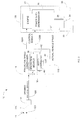
- FIG. 1 is a schematic diagram showing one example of a predictive speed controller 16 used in a Pedal Based Speed Control (PBSC) system 10.
- the PBSC system 10 includes an actuator 11 that is used by a vehicle operator to select a desired vehicle speed.
- the actuator 11 can be a pedal, lever, or any other type of controller used by the vehicle operator to control the speed of vehicle 10.
- a foot pedal is used as the actuator 11.
- a position sensor 14 generates a signal 100 that corresponds with the position of foot pedal 11.
- the signal 100 is also associated with a desired vehicle speed.
- the predictive speed controller 16 converts the desired speed signal 100 from position sensor 14 into one or more speed control signals 128 that control the actual speed 110 of a vehicle 108.
- a first speed control signal 128A may control the speed of an engine 24 and one or more other speed control signals 128B may control the operations of a power shift transmission 26.
- the engine 24 and power shift transmission 26 combine to control the rotational speed of an output shaft 28 that, in turn, control the rotational speed of a drive axle 34 and wheels 30.
- Delays in the vehicle 108 can create different speed control problems.
- an operator may press down or lift up on the foot pedal 11 to either increase or decrease the speed of vehicle 108.
- Consequences of this delayed vehicle response include reduced vehicle stability, poor pedal based speed control that results in jerks, and slow response due to compromises in gain turning.
- the predictive speed controller 16 compensates for these inherent vehicle time delays.
- the predictive speed controller 16 in one example, is a microprocessor that executes software instructions that are stored in either internal or external memory. In other embodiments, the predictive speed controller 16 may be implemented using discrete logic elements and/or electro-mechanical components.
- the predictive speed controller 16 monitors the desired vehicle speed 100 associated with the foot pedal position 12 and simulates vehicle responses 38 that essentially predict what vehicle speed was actually intended by the vehicle operator. In one embodiment, the controller 16 uses one or more prediction models 36 to generate the simulated vehicle responses 38. The controller 16 then uses a compensation value derived from the simulated vehicle responses 38 to adjust the speed control signals 128 used for controlling the speed of vehicle 108.
- predictive speed control may be limited by the accuracy of the models 36 used for simulating/predicting the vehicle response.
- a model corrector 40 is used to dynamically identify errors in the prediction models 36.
- the model corrector 40 identifies the modeling error by comparing the simulated vehicle response 38 with the actual vehicle speed 110.
- a correction value 42 corresponding to the identified modeling error is applied to one or more of the models 36.
- the corrected model response 38 is then used for generating a more accurate speed compensation value.
- a Look-Up Table (LUT) 44 contains different gain values associated with different vehicle speeds 110. The gain value associated with the currently detected vehicle speed 110 is then used to dynamically correct for the detected modeling error.
- the LUT 44 may contain different predetermined sets of gain values that can be used for different vehicle operations or different vehicle conditions. For example, a first set of gain values may be used when the vehicle 108 is carrying little or no load, and a second set of gain values may be used when the vehicle 10 is carrying a relatively heavy load.
- the model corrector 40 may use yet another set of gain values when the vehicle is traveling at different speed ranges or when traveling down or up different grades.
- the predictive speed controller 16 monitors a pedal position 12 that correspond to a desired vehicle speed 100.
- Prediction models 36 simulate vehicle responses corresponding to the desired vehicle speed to identify predicted speed differences between a vehicle response with a time delay and a vehicle response without a time delay. This predicted speed difference corresponds with a prediction of an intended speed. The prediction results are then used to compensate for time delays in the actual vehicle response.
- the predictive speed controller 16 provides steady slow speeds when the vehicle 108 travels down a slope, allows small slow speed position changes close to loads when beginning from a stopped position, improves steady travel speed on level surfaces when sudden throttle commands are initiated, and eliminates abrupt vehicle acceleration and deceleration (jerk).
- FIG. 3 shows in more detail one implementation of the predictive speed controller 16 that uses a Smith Predictor 118.
- FIG. 4 provides a more detailed description of the operations performed in FIG. 3 . The descriptions of the operations in FIGS. 3 and 4 are described below.
- the desired control force 128 is increased when the value for the tracking error 126 is positive (+), corresponding to vehicle acceleration.
- the desired control force 128 is decreased when the value of the tracking error 126 is negative (-), corresponding to vehicle deceleration.
- the Smith Predictor 118 derives a time delay compensation value 122 by comparing and feeding back the predicted speed values output by the two models 112 and 114.
- Model 112 generates a predicted vehicle speed with a time delay 116 and model 114 generates a predicted vehicle speed with no time delay 120. Since the Smith Predictor 118 is an open-loop compensation system, more accurate real-world system models 112 and 114 will provide more accurate vehicle speed prediction. However, the time delay compensation value 122 may drift over time, if the vehicle system models 112 and 114 do not match the real-world vehicle 108.
- FIG. 5 shows a Laplace representation of a predictive speed controller 16 that uses the ESP 130 and FIG. 6 further describes the operations shown in FIG. 5 .
- the operations 100-128 are substantially the same as previously described in FIGS. 3 and 4 , but are explained again for completeness.
- the model corrector 132 identifies the difference (modeling error) 134 between the predicted vehicle travel speed with time delay 116 and the actual vehicle travel speed 110 for the vehicle 108.
- the model corrector 132 applies the amplified gain K to the modeling error 134 and feeds the amplified modeling error 136 back into both model 112 and model 114.
- K the gain of the output 122 of ESP 130
- the output 122 of ESP 130 will asymptotically converge to the time-delay generated output offset, and therefore compensate for the modeling error.
- the predictive speed controller 16 with the Enhanced Smith Predictor (ESP) 130 is used to control the engine 24 and the power shift transmission 26 in an industrial vehicle 108, such as a lift truck.
- ESP 130 described above can be used to achieve target behaviors for any physical system that exhibits time delays when executing commands. This could include vehicle or control system that exhibit time delays.
- the desired vehicle travel speed 100 may be controlled by a vehicle operator.
- the vehicle operator may move the position of pedal 11 to change a desired speed for the vehicle 108.
- the position sensor 14 sends a signal corresponding to the pedal position 12 to the predictive speed controller 16.
- the operations performed by the predictive speed controller 16 are carried out by a microcontroller or microprocessor that executes software instructions stored in a storage medium.
- the microprocessor operating predictive speed controller 16 converts the foot pedal position signal from position sensor 14 into the desired travel speed 100.
- the desired travel speed 100 is compared with the final predicted travel speed 124 to produce the predicted travel speed tracking error 126.
- the PI controller 104 is another function performed by the microprocessor that generates a desired control force 128.
- the desired control force 128 can be different control signals or data sent to the real-world vehicle system 108.
- the real-world vehicle system 108 may include one or more microcontrollers, valves, power shift transmission 26, engine 24, drive axle 34, and wheels 30, among other things.
- the control signals corresponding to the desired control force 128 are acted upon by the real-world vehicle system 108 to produce the actual vehicle travel speed 110.
- the speed control information associated with the desired control force 128 is also fed into the Enhanced Smith Predictor 130 and combined with the modeling error feedback value 136 generated from the model corrector 132.
- the sum of the desired control force 128 and the error feedback value 136 is input into both mathematical models 112 and 114.
- the predicted/simulated travel speed with time delay 116 is fed into the model corrector 132.
- the model corrector 132 determines the difference 134 between the predicted vehicle travel speed with time delay 116 and the actual vehicle travel speed 110.
- the model corrector 132 then applies a gain value K to the difference 134 to produce the modeling error feedback value 136.
- the sum of the modeling error feedback value 136 and the desired control force 128 works to create the predicted travel speed with time delay 116 that asymptotically converges to the real world vehicle speed 110, and thereby compensates the modeling error.
- the sum of the desired control force 128 and modeling error feedback value 136 is input into both the model 112 and the model 114.
- the predicted travel speed with time delay 116 from model 112 is compared with the predicted travel speed with no time delay 120 from model 114 to produce the time delay compensation value 122.
- a sum of the time delay compensation value 122 and the actual vehicle travel speed 110 is used as the final predicted travel speed 124.
- the final predicted travel speed 124 is then used to offset the actual desired vehicle speed 100.
- the ESP 130 compensates for changes in the desired speed 100 caused by the time delay from when the operator selects a new desired speed 100 to when the industrial vehicle responds to the new selected speed.
- the ESP 130 provides a high-performance feedback control design, and therefore, achieves good PBSC performance.
- FIG. 7 shows a more detailed example of how the models 112 and 114 are implemented in the ESP 130 of FIG. 6 .
- models 112 and 114 are implemented in the ESP 130 of FIG. 6 .
- FIG. 7 shows a more detailed example of how the models 112 and 114 are implemented in the ESP 130 of FIG. 6 .
- Other model implementations could also be used.
- the original speed signal is used in place of the predicted signal from the Enhanced Smith Predictor 130, the P-gain in controller 104 is designed low, and a high I-gain is used to drive the vehicle 108.
- FIGS. 8A-8C describe in more detail how the predictive speed controller 16 is used in conjunction with a power shift transmission.
- FIG. 8A shows portions of the vehicle 108 including the power shift transmission 26 connected to the engine 24 by a hydraulic torque converter 206.
- An output shaft 28 of the transmission 26 is connected to the drive axle 34 that drives wheels 30.
- the power shift transmission 14 can also be used in a variety of other vehicles.
- the same microprocessor that operates the predictive speed controller 16 may also control activation of a forward clutch pack (FWD) 234 and a reverse clutch pack (REV) 232 in the transmission 26 using any of the predictive speed control schemes described above.
- a control valve 230 in the transmission 26 controls fluid pressure that activates the two clutch packets 232 and 234.
- the controller 16 receives vehicle speed and direction signal 110 from the vehicle speed sensor 27 indicating the rotational speed and direction of the axle 28.
- a converter speed signal 204 is generated from a torque converter speed sensor 202 and indicates the rotational speed of an output shaft 246 ( FIG. 8B ) of the torque converter 206.
- An engine speed signal 214 is generated from an engine speed sensor 212 and indicates how fast an output shaft 242 ( FIG. 8B ) of the engine 24 is rotating.
- An engine governor control signal 210 controls a throttle valve 208 that controls the speed of engine 24.
- the controller 16 receives the pedal position signal 100 from the position sensor 14 on foot pedal 11.
- the pedal position can alternatively refer to a throttle value, acceleration value, or a deceleration value.
- a forward-reverse direction signal 226 is generated by a direction lever or pedal 224 and indicates a forward or backward direction the vehicle operator selects for the vehicle 108.
- An internal or external memory 222 contains mapped parameters identifying clutch pack pressure values and other control parameters used for performing different braking and speed control operations. The controller 16 selects these different pressure values according one or more of the predictive speed control schemes described above.
- the memory 222 also contains the predetermined gain values used for correcting error in the prediction models (see FIGS. 2 , 5 , and 6 )
- FIG. 8B is a more detailed schematic diagram of a single speed power shift transmission.
- the torque converter 206 includes an impeller pump 240 and a turbine 244.
- a shaft 242 extends from the impeller pump 240 and is coupled to the crankshaft of engine 24.
- a shaft 246 extends from the turbine 244 and is coupled to the input of power shift transmission 26.
- the torque converter 206 continuously varies the ratio of the speed of the output shaft 246 to the speed of the input shaft 242 in accordance with the load on the output shaft 246.
- the forward clutch pack 234 and the reverse clutch pack 232 each selectively engages and disengages the input shaft 246 with the output shaft 28 through the forward gears 252 and reverse gears 254.
- the engaging force of the clutches 234 and 232 are controlled by changing the oil pressure in oil chambers 234 C and 232C, respectively.
- the oil pressures provided by the control valve 230 is controlled by the desired control force signals 128 generated by the predictive speed controller 16 ( FIG. 8A ).
- the clutch packs 234 and 232 are multiple disc hydraulic wet clutches.
- clutches 234 and 232 disconnect the output shaft 28 from the input shaft 246.
- the clutch pressure for either of the clutch packs is at a maximum pressure
- the corresponding clutch pack maximizes the engaging force (locking).
- the clutch pack pressure is between zero and the maximum value, the corresponding clutch pack is partially engaged.
- the partially engaged condition is referred to as clutch pack slipping.
- a FWD-1 signal 218 in FIG. 8A controls the oil pressure in the forward clutch pack 234.
- a REV-1 signal 216 in FIG. 8A controls the oil pressure in the REV clutch pack 232.
- the forward clutch pack 234 When the vehicle 10 is moving in a forward direction at a high speed in forward gear 252, the forward clutch pack 234 is partially engaged (not locked) and reverse clutch pack 232 and forward clutch pack 234 operate as a hydraulic brake.
- the reverse clutch 232 When the vehicle is moving backwards, in reverse gear 254, the reverse clutch 232 is partially engaged (not locked) and the forward clutch 234 and reverse clutch 232 operate as a hydraulic brake.
- the two speed PS transmission is shown in FIG. 8C and includes two forward gears 260 and 250 and one reverse gear 254.
- a second forward multiple disk hydraulic wet clutch 262 selectively engages and disengages the input shaft 246 with the output shaft 28 through high forward gear 260.
- the high forward clutch 262 When the vehicle 10 is moving in a forward direction at a high speed in high gear 260, the high forward clutch 262 is partially engaged (not locked) and the low forward clutch 234 and high forward clutch 262 operate as a hydraulic brake.
- the forward low clutch 234 When the vehicle 10 is moving in a forward direction at a slower speed, the forward low clutch 234 is partially engaged (not locked) and the reverse clutch 232 and low forward clutch 234 function as a hydraulic brake.
- the reverse clutch 232 When the vehicle 10 is moving backward, the reverse clutch 232 is engaged (not locked) and the forward clutch 234 and reverse clutch 232 function as a hydraulic brake.
- the single speed PS transmission in FIG. 8B , the multi-speed PS transmission shown in FIG. 8C , or any other combination of gears and clutch packs, can be controlled using the predictive speed controller 16 as described above in FIGS. 1-7 .
- the predictive speed controller 16 provides improved PBSC control of vehicles that use power shift transmissions. Specifically, the predictive speed controller 16 significantly improves travel speed control performance and eliminates abrupt acceleration and deceleration (jerk) due to time delays in vehicle response. In one application, the predictive speed controller 16 allows an operator to control the power shift transmission 26 very much like a highly responsive hydrostatic transmission. As a result, the vehicle 108 provides many of the control benefits of a hydrostatic transmission at the lower cost of a power shift transmission.
- the system described above can use dedicated processor systems, micro controllers, programmable logic devices, or microprocessors that perform some or all of the operations. Some of the operations described above may be implemented in software and other operations may be implemented in hardware.
Landscapes
- Engineering & Computer Science (AREA)
- Combustion & Propulsion (AREA)
- Chemical & Material Sciences (AREA)
- Mechanical Engineering (AREA)
- Transportation (AREA)
- Automation & Control Theory (AREA)
- Physics & Mathematics (AREA)
- Evolutionary Computation (AREA)
- General Physics & Mathematics (AREA)
- Software Systems (AREA)
- Medical Informatics (AREA)
- Health & Medical Sciences (AREA)
- Computer Vision & Pattern Recognition (AREA)
- Artificial Intelligence (AREA)
- Mathematical Physics (AREA)
- Human Computer Interaction (AREA)
- Control Of Transmission Device (AREA)
- Control Of Driving Devices And Active Controlling Of Vehicle (AREA)
- Control Of Vehicle Engines Or Engines For Specific Uses (AREA)
Priority Applications (1)
| Application Number | Priority Date | Filing Date | Title |
|---|---|---|---|
| EP17182190.3A EP3275750A1 (fr) | 2007-10-26 | 2008-10-24 | Organe de commande de véhicule prédictif |
Applications Claiming Priority (2)
| Application Number | Priority Date | Filing Date | Title |
|---|---|---|---|
| US98301807P | 2007-10-26 | 2007-10-26 | |
| US12/256,445 US8135531B2 (en) | 2002-06-12 | 2008-10-22 | Predictive vehicle controller |
Related Child Applications (2)
| Application Number | Title | Priority Date | Filing Date |
|---|---|---|---|
| EP17182190.3A Division-Into EP3275750A1 (fr) | 2007-10-26 | 2008-10-24 | Organe de commande de véhicule prédictif |
| EP17182190.3A Division EP3275750A1 (fr) | 2007-10-26 | 2008-10-24 | Organe de commande de véhicule prédictif |
Publications (3)
| Publication Number | Publication Date |
|---|---|
| EP2052925A2 true EP2052925A2 (fr) | 2009-04-29 |
| EP2052925A3 EP2052925A3 (fr) | 2010-09-08 |
| EP2052925B1 EP2052925B1 (fr) | 2017-08-30 |
Family
ID=40229934
Family Applications (2)
| Application Number | Title | Priority Date | Filing Date |
|---|---|---|---|
| EP08167535.7A Not-in-force EP2052925B1 (fr) | 2007-10-26 | 2008-10-24 | Contrôleur de véhicule prédictif |
| EP17182190.3A Withdrawn EP3275750A1 (fr) | 2007-10-26 | 2008-10-24 | Organe de commande de véhicule prédictif |
Family Applications After (1)
| Application Number | Title | Priority Date | Filing Date |
|---|---|---|---|
| EP17182190.3A Withdrawn EP3275750A1 (fr) | 2007-10-26 | 2008-10-24 | Organe de commande de véhicule prédictif |
Country Status (2)
| Country | Link |
|---|---|
| US (1) | US8135531B2 (fr) |
| EP (2) | EP2052925B1 (fr) |
Cited By (2)
| Publication number | Priority date | Publication date | Assignee | Title |
|---|---|---|---|---|
| DE102015223611A1 (de) * | 2015-11-27 | 2017-06-01 | Bayerische Motoren Werke Aktiengesellschaft | Verfahren und Steuereinheit zur Beschleunigungsüberwachung und -anpassung |
| CN107264510A (zh) * | 2017-06-16 | 2017-10-20 | 湖南大学 | 一种基于交通拥堵情况的车辆动力控制系统及方法 |
Families Citing this family (50)
| Publication number | Priority date | Publication date | Assignee | Title |
|---|---|---|---|---|
| US11220179B2 (en) | 2005-11-17 | 2022-01-11 | Invently Automotive Inc. | Vehicle power management system determining route segment length |
| US11247564B2 (en) | 2005-11-17 | 2022-02-15 | Invently Automotive Inc. | Electric vehicle power management system |
| US11214144B2 (en) | 2005-11-17 | 2022-01-04 | Invently Automotive Inc. | Electric vehicle power management system |
| US11279234B2 (en) | 2005-11-17 | 2022-03-22 | Invently Automotive Inc. | Vehicle power management system |
| US11351863B2 (en) | 2005-11-17 | 2022-06-07 | Invently Automotive Inc. | Vehicle power management system |
| US11230190B2 (en) | 2005-11-17 | 2022-01-25 | Invently Automotive Inc. | Electric vehicle power management system |
| US11345236B2 (en) | 2005-11-17 | 2022-05-31 | Invently Automotive Inc. | Electric vehicle power management system |
| US11254211B2 (en) | 2005-11-17 | 2022-02-22 | Invently Automotive Inc. | Electric vehicle power management system |
| US11279233B2 (en) | 2005-11-17 | 2022-03-22 | Invently Automotive Inc. | Electric vehicle power management system |
| US11370302B2 (en) | 2005-11-17 | 2022-06-28 | Invently Automotive Inc. | Electric vehicle power management system |
| US11084377B2 (en) | 2005-11-17 | 2021-08-10 | Invently Automotive Inc. | Vehicle power management system responsive to voice commands from a Gps enabled device |
| US11225144B2 (en) | 2005-11-17 | 2022-01-18 | Invently Automotive Inc. | Vehicle power management system |
| US11207981B2 (en) | 2005-11-17 | 2021-12-28 | Invently Automotive Inc. | Vehicle power management system |
| US11186175B2 (en) | 2005-11-17 | 2021-11-30 | Invently Automotive Inc. | Vehicle power management system |
| US10882399B2 (en) | 2005-11-17 | 2021-01-05 | Invently Automotive Inc. | Electric vehicle power management system |
| US11207980B2 (en) | 2005-11-17 | 2021-12-28 | Invently Automotive Inc. | Vehicle power management system responsive to traffic conditions |
| US11390165B2 (en) | 2005-11-17 | 2022-07-19 | Invently Automotive Inc. | Electric vehicle power management system |
| US11325468B2 (en) | 2005-11-17 | 2022-05-10 | Invently Automotive Inc. | Vehicle power management system |
| US11267338B2 (en) | 2005-11-17 | 2022-03-08 | Invently Automotive Inc. | Electric vehicle power management system |
| US11180025B2 (en) | 2005-11-17 | 2021-11-23 | Invently Automotive Inc. | Electric vehicle power management system |
| US8712650B2 (en) | 2005-11-17 | 2014-04-29 | Invent.Ly, Llc | Power management systems and designs |
| US11186173B2 (en) | 2005-11-17 | 2021-11-30 | Invently Automotive Inc. | Electric vehicle power management system |
| US11267339B2 (en) | 2005-11-17 | 2022-03-08 | Invently Automotive Inc. | Vehicle power management system |
| US11186174B2 (en) | 2005-11-17 | 2021-11-30 | Invently Automotive Inc. | Vehicle power management system |
| US11285810B2 (en) | 2005-11-17 | 2022-03-29 | Invently Automotive Inc. | Vehicle power management system |
| US8041492B2 (en) * | 2006-10-31 | 2011-10-18 | Clark Equipment Company | Engine load management for power machines |
| ES2370806T3 (es) * | 2007-02-12 | 2011-12-22 | Saab Ab | Sistema de control de un vehículo y procedimiento que usa la asignación de control y la compensación de fase. |
| US7969358B2 (en) * | 2008-11-19 | 2011-06-28 | Harris Corporation | Compensation of beamforming errors in a communications system having widely spaced antenna elements |
| US20100125347A1 (en) * | 2008-11-19 | 2010-05-20 | Harris Corporation | Model-based system calibration for control systems |
| US20100124263A1 (en) * | 2008-11-19 | 2010-05-20 | Harris Corporation | Systems for determining a reference signal at any location along a transmission media |
| US8170088B2 (en) * | 2008-11-19 | 2012-05-01 | Harris Corporation | Methods for determining a reference signal at any location along a transmission media |
| US7970365B2 (en) * | 2008-11-19 | 2011-06-28 | Harris Corporation | Systems and methods for compensating for transmission phasing errors in a communications system using a receive signal |
| US20100123618A1 (en) * | 2008-11-19 | 2010-05-20 | Harris Corporation | Closed loop phase control between distant points |
| KR101494030B1 (ko) * | 2010-07-02 | 2015-02-16 | 엘에스산전 주식회사 | 전기자동차용 인버터 |
| US8457827B1 (en) * | 2012-03-15 | 2013-06-04 | Google Inc. | Modifying behavior of autonomous vehicle based on predicted behavior of other vehicles |
| IL224273B (en) * | 2013-01-17 | 2018-05-31 | Cohen Yossi | Delay compensation during remote sensor control |
| US9120658B2 (en) * | 2013-12-27 | 2015-09-01 | Komatsu Ltd. | Forklift and control method of forklift |
| US9187093B1 (en) | 2014-08-04 | 2015-11-17 | Cummins, Inc. | Systems and methods of cruise droop control |
| US10386796B2 (en) * | 2014-12-11 | 2019-08-20 | University Of New Brunswick | Model predictive controller and method with correction parameter to compensate for time lag |
| FR3039130B1 (fr) * | 2015-07-21 | 2019-05-31 | Airbus Operations | Procede et dispositif de gestion automatique d’un actionneur commande par une servo-vanne. |
| WO2017022413A1 (fr) * | 2015-07-31 | 2017-02-09 | 日立オートモティブシステムズ株式会社 | Dispositif d'aide au stationnement pour véhicule |
| DE102015015923A1 (de) * | 2015-12-09 | 2017-06-14 | Wabco Gmbh | Verfahren zum adaptiven Regeln einer Fahrzeuggeschwindigkeit in einem Fahrzeug sowie Geschwindigkeitsregelanlage zum Durchführen des Verfahrens |
| ES2833674T3 (es) * | 2016-06-08 | 2021-06-15 | Uisee Tech Beijing Ltd | Método y aparato de planificación de velocidad y aparato de cálculo para la conducción automática de un vehículo |
| AT519547B1 (de) * | 2017-06-22 | 2018-08-15 | Avl List Gmbh | Vorrichtung und Verfahren zur prädiktiven Steuerung der Geschwindigkeit eines Fahrzeugs |
| DE102017010180B3 (de) | 2017-10-30 | 2019-04-04 | Daimler Ag | Verfahren und Vorrichtung zur Regelung einer Längsposition eines Fahrzeugs |
| FR3090546B1 (fr) * | 2018-12-21 | 2020-12-18 | Psa Automobiles Sa | Système de contrôle d'amortissement d’oscillations dans une chaîne de traction à moteur thermique |
| CN109634120B (zh) * | 2018-12-26 | 2022-06-03 | 东软集团(北京)有限公司 | 一种车辆控制方法及装置 |
| CN112987555B (zh) * | 2019-12-12 | 2022-10-11 | 天津大学 | 一种无人驾驶碾压机后退过程的复合抗扰轨迹跟踪控制算法 |
| US11453409B2 (en) * | 2020-04-21 | 2022-09-27 | Baidu Usa Llc | Extended model reference adaptive control algorithm for the vehicle actuation time-latency |
| CN116603142B (zh) * | 2023-05-24 | 2025-11-14 | 北京瑞承天启医疗科技有限公司 | 用于呼吸机的氧浓度控制方法和呼吸机 |
Citations (1)
| Publication number | Priority date | Publication date | Assignee | Title |
|---|---|---|---|---|
| US6684148B2 (en) | 2002-06-12 | 2004-01-27 | Nacco Materials Handling Group, Inc. | Transmission control system |
Family Cites Families (70)
| Publication number | Priority date | Publication date | Assignee | Title |
|---|---|---|---|---|
| GB1050283A (fr) | 1900-01-01 | |||
| GB717868A (en) | 1952-04-07 | 1954-11-03 | Gen Motors Corp | Improved variable-speed power transmission mechanism for motor vehicles |
| US2757552A (en) | 1948-12-30 | 1956-08-07 | Borg Warner | Hydraulic controls for transmissions |
| GB730576A (en) | 1951-05-01 | 1955-05-25 | Gen Tire & Rubber Co | Torque transmitting devices such as clutches or brakes |
| US2938403A (en) | 1954-10-14 | 1960-05-31 | Borg Warner | Control for transmission |
| GB807395A (en) | 1956-06-21 | 1959-01-14 | Gen Motors Corp | Improved control system for variable-speed power transmission mechanism for motor vehicles |
| US3053116A (en) | 1958-04-25 | 1962-09-11 | Gen Motors Corp | Transmission |
| US3096667A (en) | 1960-08-15 | 1963-07-09 | Caterpillar Tractor Co | Transmission system and hydraulic controls therefor |
| DE1178307B (de) | 1960-12-17 | 1964-09-17 | Zahnradfabrik Friedrichshafen | Hydrodynamisch-mechanisches Getriebe, insbesondere fuer Kraftfahrzeuge |
| US3167970A (en) | 1962-04-23 | 1965-02-02 | Borg Warner | Manual and automatic transmission |
| US3158037A (en) | 1962-10-12 | 1964-11-24 | Ford Motor Co | Control valve system |
| US3258984A (en) | 1963-12-31 | 1966-07-05 | Ford Motor Co | Ratio shift-point control system for a power transmission mechanism |
| US3442152A (en) | 1964-06-18 | 1969-05-06 | Gen Motors Corp | Transmission and controls |
| US3561293A (en) | 1967-12-22 | 1971-02-09 | Nissan Motor | Hydraulic control system for automatic transmission |
| US3692160A (en) | 1970-08-24 | 1972-09-19 | Twin Disc Inc | Fluid power control system for vehicles |
| US3688607A (en) | 1971-05-26 | 1972-09-05 | Gen Motors Corp | Transmission and control |
| JPS5214390B2 (fr) | 1971-12-28 | 1977-04-21 | ||
| US3893552A (en) | 1973-10-05 | 1975-07-08 | Horton Mfg Co Inc | Clutch and brake with interlock valves |
| DE2716531C2 (de) | 1976-04-14 | 1982-10-28 | Twin Disc Inc., 53402 Racine, Wis. | Hydraulische Steuervorrichtung für Wechsel-Wendegetriebe |
| US4104991A (en) | 1976-08-23 | 1978-08-08 | Ford Motor Company | Circuit for controlling the operability of one or more cylinders of a multicylinder internal combustion engine |
| US4129148A (en) | 1977-06-30 | 1978-12-12 | International Harvester Company | Clutch modulator |
| CA1118235A (fr) | 1978-10-30 | 1982-02-16 | Albert A. Miller | Ralentisseur pour vehicules motorises |
| DE3135055C2 (de) | 1981-09-04 | 1984-04-26 | Jörg Prof. Dipl.-Ing.(FH) 7072 Heubach Linser | Brems-Kupplungs-Kombination |
| US4574927A (en) | 1983-12-19 | 1986-03-11 | Clark Michigan Company | Forward and reverse clutch engagement parking brake |
| EP0292648B1 (fr) | 1987-05-22 | 1992-08-19 | ALFRED TEVES GmbH | Installation de freinage avec régulation antiblocage et/ou anti-patinage d'entraînement ainsi que modulateur de pression de freinage pour une telle installation de freinage |
| JP2611239B2 (ja) | 1987-07-16 | 1997-05-21 | トヨタ自動車株式会社 | 車速制御装置 |
| JPH01240350A (ja) | 1988-03-23 | 1989-09-25 | Kubota Ltd | 車輌の制動装置 |
| JPH037625A (ja) | 1989-06-02 | 1991-01-14 | Mitsubishi Motors Corp | 車両用自動走行制御装置 |
| JPH03292456A (ja) | 1990-04-10 | 1991-12-24 | Toyota Motor Corp | 車両用自動変速機の変速制御方法 |
| US5048655A (en) | 1990-05-22 | 1991-09-17 | Deere & Company | Electric declutch mechanism for direct drive crawler |
| JP3031982B2 (ja) | 1990-09-26 | 2000-04-10 | マツダ株式会社 | 車両の制御装置 |
| JP2756354B2 (ja) | 1990-10-02 | 1998-05-25 | 本田技研工業株式会社 | 車輌用自動変速機の制御装置 |
| JPH04325733A (ja) | 1991-04-25 | 1992-11-16 | Fuji Heavy Ind Ltd | 自動変速機付車両のエンジン制御装置 |
| GB2262818B (en) | 1991-12-24 | 1995-06-21 | Ricardo International Plc | Oscillation reduction |
| JPH0634027A (ja) | 1992-07-10 | 1994-02-08 | Nippondenso Co Ltd | トルク検出機能付き摩擦伝動装置 |
| JP2811523B2 (ja) | 1993-02-26 | 1998-10-15 | 小松フォークリフト株式会社 | 産業車両の荷役及び走行制御装置 |
| DE4321413C2 (de) | 1993-06-26 | 1996-04-11 | Bosch Gmbh Robert | Verfahren und Vorrichtung zur Steuerung der Antriebsleistung eines Fahrzeugs |
| US5568378A (en) | 1994-10-24 | 1996-10-22 | Fisher-Rosemount Systems, Inc. | Variable horizon predictor for controlling dead time dominant processes, multivariable interactive processes, and processes with time variant dynamics |
| US5651436A (en) | 1995-04-20 | 1997-07-29 | Midwest Brake Bond Company | Brake and clutch control system |
| DE19517888A1 (de) | 1995-05-16 | 1996-11-21 | Zahnradfabrik Friedrichshafen | Unter Last schaltbares Wendegetriebe |
| US5868214A (en) * | 1995-08-29 | 1999-02-09 | Cummins Engine Company, Inc. | Cruise control governor using optimal droop selection logic |
| FR2739064B1 (fr) | 1995-09-22 | 1997-10-31 | Renault | Procede de limitation du couple d'une transmission automatique |
| US5901059A (en) | 1996-09-13 | 1999-05-04 | Honeywell Measurex Corp | Method and apparatus for controlling a process using adaptive prediction feedback |
| JP3596213B2 (ja) | 1997-02-21 | 2004-12-02 | 日産自動車株式会社 | エンジン制御装置 |
| US6186029B1 (en) | 1997-07-09 | 2001-02-13 | Dana Corporation | Dual input transmission |
| JPH1178617A (ja) | 1997-09-05 | 1999-03-23 | Nissan Motor Co Ltd | エンジン・自動変速機の総合制御装置 |
| JP3007625B1 (ja) | 1998-12-10 | 2000-02-07 | 日本アンテナ株式会社 | モニタ端子を備える双方向増幅器 |
| JP3799903B2 (ja) | 1999-02-24 | 2006-07-19 | 株式会社豊田自動織機 | 産業車両の駐車ブレーキ装置 |
| JP2001116070A (ja) | 1999-10-18 | 2001-04-27 | Toyota Autom Loom Works Ltd | 産業車両の制動制御装置 |
| US6782961B1 (en) | 1999-10-18 | 2004-08-31 | Kabushiki Kaisha Toyoda Jidoshokki Seisakusho | Driving control apparatus for industrial vehicle |
| US6335609B1 (en) | 2000-05-09 | 2002-01-01 | Ford Global Technologies, Inc. | Method for reducing peak phase current and decreasing staring time for an internal combustion engine having an induction machine |
| US6424902B1 (en) * | 2000-10-30 | 2002-07-23 | Caterpillar Inc. | Method and apparatus for operating a continuously variable transmission in the torque limited region near zero output speed |
| JP3441722B2 (ja) | 2000-12-22 | 2003-09-02 | 株式会社資生堂 | 化粧料 |
| JP4060537B2 (ja) | 2001-02-07 | 2008-03-12 | 株式会社エクセディ | 車輌の補助ブレーキシステム |
| JP2002367299A (ja) | 2001-06-07 | 2002-12-20 | Sony Corp | 光学ピックアップの送り機構及びディスクドライブ装置 |
| JP2003182408A (ja) | 2001-12-21 | 2003-07-03 | Toyota Motor Corp | 自動変速機の制御装置 |
| US6910359B2 (en) | 2002-05-07 | 2005-06-28 | Hi-Tech Welding Services, Inc. | Die apparatus and method for high temperature forming of metal products |
| US7974760B2 (en) | 2003-10-20 | 2011-07-05 | Nmhg Oregon, Inc. | Advanced power-shift transmission control system |
| JP3830912B2 (ja) | 2003-03-17 | 2006-10-11 | 小松フォークリフト株式会社 | 産業用車両の走行制御装置 |
| SE526348C2 (sv) | 2003-08-27 | 2005-08-30 | Volvo Lastvagnar Ab | Förfarande och arrangemang för att styra vridmoment i en drivlina hos ett landfordon |
| US6901324B2 (en) | 2003-09-30 | 2005-05-31 | Caterpillar Inc | System and method for predictive load management |
| US7146263B2 (en) | 2003-09-30 | 2006-12-05 | Caterpillar Inc | Predictive load management system |
| US7563196B2 (en) | 2004-04-27 | 2009-07-21 | Denso Corporation | Controller for automatic transmission |
| JP4140567B2 (ja) | 2004-07-14 | 2008-08-27 | 松下電器産業株式会社 | 物体追跡装置および物体追跡方法 |
| US7006909B1 (en) | 2004-10-20 | 2006-02-28 | Detroit Diesel Corporation | Engine delay compensation |
| JP4869951B2 (ja) | 2005-01-19 | 2012-02-08 | オリンパス株式会社 | 医療機器データ解析装置 |
| CN101128563B (zh) | 2005-02-28 | 2012-05-23 | 三菱化学株式会社 | 荧光体、其制造方法及其应用 |
| US20060293822A1 (en) | 2005-06-27 | 2006-12-28 | Freightliner Llc | Predictive control method and apparatus for vehicle automatic transmission |
| JP4609390B2 (ja) | 2005-09-30 | 2011-01-12 | 株式会社豊田自動織機 | フォークリフトの走行制御装置 |
| JP4134141B2 (ja) | 2005-10-20 | 2008-08-13 | 株式会社ジェイワンホーム | 床面コンクリートのレベル施工方法及びレベル表示具 |
-
2008
- 2008-10-22 US US12/256,445 patent/US8135531B2/en not_active Expired - Fee Related
- 2008-10-24 EP EP08167535.7A patent/EP2052925B1/fr not_active Not-in-force
- 2008-10-24 EP EP17182190.3A patent/EP3275750A1/fr not_active Withdrawn
Patent Citations (2)
| Publication number | Priority date | Publication date | Assignee | Title |
|---|---|---|---|---|
| US6684148B2 (en) | 2002-06-12 | 2004-01-27 | Nacco Materials Handling Group, Inc. | Transmission control system |
| US6950737B2 (en) | 2002-06-12 | 2005-09-27 | Nacco Materials Handling Group, Inc. | Transmission control system |
Cited By (3)
| Publication number | Priority date | Publication date | Assignee | Title |
|---|---|---|---|---|
| DE102015223611A1 (de) * | 2015-11-27 | 2017-06-01 | Bayerische Motoren Werke Aktiengesellschaft | Verfahren und Steuereinheit zur Beschleunigungsüberwachung und -anpassung |
| DE102015223611B4 (de) | 2015-11-27 | 2023-11-02 | Bayerische Motoren Werke Aktiengesellschaft | Verfahren und Steuereinheit zur Beschleunigungsüberwachung und -anpassung |
| CN107264510A (zh) * | 2017-06-16 | 2017-10-20 | 湖南大学 | 一种基于交通拥堵情况的车辆动力控制系统及方法 |
Also Published As
| Publication number | Publication date |
|---|---|
| US20090048748A1 (en) | 2009-02-19 |
| EP2052925A3 (fr) | 2010-09-08 |
| US8135531B2 (en) | 2012-03-13 |
| EP2052925B1 (fr) | 2017-08-30 |
| EP3275750A1 (fr) | 2018-01-31 |
Similar Documents
| Publication | Publication Date | Title |
|---|---|---|
| EP2052925B1 (fr) | Contrôleur de véhicule prédictif | |
| US8715136B1 (en) | Torque converter slip control based on motor torque during transient events | |
| US7908066B2 (en) | Powertrain of a motor vehicle and method for controlling said powertrain | |
| EP2971836B1 (fr) | Systèmes de commande d'embrayage de véhicule | |
| JP5152003B2 (ja) | 前後加速度制御装置 | |
| CN109572665B (zh) | 基于动力系mpc的线性化模型 | |
| US9879769B2 (en) | Torque converter clutch slip control | |
| JPWO2012133059A1 (ja) | ハイブリッド車両の変速制御装置 | |
| KR100779175B1 (ko) | 차량 통합 제어 시스템의 동력 계통 제어 장치 | |
| CN103802824A (zh) | 学习混合动力车辆的发动机离合器的操作的方法和系统 | |
| CA2631433A1 (fr) | Controleur de vehicule | |
| JP5316576B2 (ja) | 車両制御装置 | |
| US10821817B2 (en) | Torque or power monitor | |
| US20150166067A1 (en) | System and method for controlling the speed of an engine | |
| EP1950394A1 (fr) | Dispositif de commande of vehicule | |
| JP7036342B2 (ja) | ハイブリッド車両の制御装置 | |
| US9079574B2 (en) | Method for controlling a motor vehicle powertrain | |
| JP7036341B2 (ja) | ハイブリッド車両の制御装置 | |
| CN114802275B (zh) | 控制装置及控制系统 | |
| US7689339B2 (en) | Vehicle driving force control apparatus and driving force control method | |
| JP2022030956A (ja) | 油圧算出装置 | |
| SANADA et al. | 2D34 Torque observer and decoupling control of automatic transmission (The 12th International Conference on Motion and Vibration Control) | |
| GB2639903A (en) | A control scheme for controlling acceleration of a vehicle | |
| Anwar et al. | Optimal control of an On-Demand All-Wheel Drive system (ODAWD) for vehicle traction enhancement | |
| SE540472C2 (en) | Method and system for controlling a clutch of a vehicle |
Legal Events
| Date | Code | Title | Description |
|---|---|---|---|
| PUAI | Public reference made under article 153(3) epc to a published international application that has entered the european phase |
Free format text: ORIGINAL CODE: 0009012 |
|
| AK | Designated contracting states |
Kind code of ref document: A2 Designated state(s): AT BE BG CH CY CZ DE DK EE ES FI FR GB GR HR HU IE IS IT LI LT LU LV MC MT NL NO PL PT RO SE SI SK TR |
|
| AX | Request for extension of the european patent |
Extension state: AL BA MK RS |
|
| PUAL | Search report despatched |
Free format text: ORIGINAL CODE: 0009013 |
|
| AK | Designated contracting states |
Kind code of ref document: A3 Designated state(s): AT BE BG CH CY CZ DE DK EE ES FI FR GB GR HR HU IE IS IT LI LT LU LV MC MT NL NO PL PT RO SE SI SK TR |
|
| AX | Request for extension of the european patent |
Extension state: AL BA MK RS |
|
| RIC1 | Information provided on ipc code assigned before grant |
Ipc: B60W 10/10 20060101ALI20100805BHEP Ipc: B60W 30/14 20060101ALI20100805BHEP Ipc: B60W 10/06 20060101AFI20090122BHEP Ipc: B60W 10/04 20060101ALI20100805BHEP Ipc: B60W 30/18 20060101ALI20100805BHEP Ipc: G05B 13/04 20060101ALI20100805BHEP Ipc: B60W 50/06 20060101ALI20100805BHEP |
|
| 17P | Request for examination filed |
Effective date: 20110222 |
|
| 17Q | First examination report despatched |
Effective date: 20110325 |
|
| AKX | Designation fees paid |
Designated state(s): AT BE BG CH CY CZ DE DK EE ES FI FR GB GR HR HU IE IS IT LI LT LU LV MC MT NL NO PL PT RO SE SI SK TR |
|
| RAP1 | Party data changed (applicant data changed or rights of an application transferred) |
Owner name: NACCO MATERIALS HANDLING GROUP, INC. |
|
| RAP1 | Party data changed (applicant data changed or rights of an application transferred) |
Owner name: HYSTER-YALE GROUP, INC. |
|
| GRAP | Despatch of communication of intention to grant a patent |
Free format text: ORIGINAL CODE: EPIDOSNIGR1 |
|
| INTG | Intention to grant announced |
Effective date: 20170330 |
|
| GRAS | Grant fee paid |
Free format text: ORIGINAL CODE: EPIDOSNIGR3 |
|
| GRAA | (expected) grant |
Free format text: ORIGINAL CODE: 0009210 |
|
| AK | Designated contracting states |
Kind code of ref document: B1 Designated state(s): AT BE BG CH CY CZ DE DK EE ES FI FR GB GR HR HU IE IS IT LI LT LU LV MC MT NL NO PL PT RO SE SI SK TR |
|
| REG | Reference to a national code |
Ref country code: GB Ref legal event code: FG4D |
|
| REG | Reference to a national code |
Ref country code: CH Ref legal event code: EP |
|
| REG | Reference to a national code |
Ref country code: AT Ref legal event code: REF Ref document number: 923212 Country of ref document: AT Kind code of ref document: T Effective date: 20170915 |
|
| REG | Reference to a national code |
Ref country code: IE Ref legal event code: FG4D |
|
| REG | Reference to a national code |
Ref country code: DE Ref legal event code: R096 Ref document number: 602008051866 Country of ref document: DE |
|
| REG | Reference to a national code |
Ref country code: FR Ref legal event code: PLFP Year of fee payment: 10 |
|
| REG | Reference to a national code |
Ref country code: NL Ref legal event code: MP Effective date: 20170830 |
|
| REG | Reference to a national code |
Ref country code: LT Ref legal event code: MG4D |
|
| REG | Reference to a national code |
Ref country code: AT Ref legal event code: MK05 Ref document number: 923212 Country of ref document: AT Kind code of ref document: T Effective date: 20170830 |
|
| PG25 | Lapsed in a contracting state [announced via postgrant information from national office to epo] |
Ref country code: AT Free format text: LAPSE BECAUSE OF FAILURE TO SUBMIT A TRANSLATION OF THE DESCRIPTION OR TO PAY THE FEE WITHIN THE PRESCRIBED TIME-LIMIT Effective date: 20170830 Ref country code: FI Free format text: LAPSE BECAUSE OF FAILURE TO SUBMIT A TRANSLATION OF THE DESCRIPTION OR TO PAY THE FEE WITHIN THE PRESCRIBED TIME-LIMIT Effective date: 20170830 Ref country code: LT Free format text: LAPSE BECAUSE OF FAILURE TO SUBMIT A TRANSLATION OF THE DESCRIPTION OR TO PAY THE FEE WITHIN THE PRESCRIBED TIME-LIMIT Effective date: 20170830 Ref country code: NO Free format text: LAPSE BECAUSE OF FAILURE TO SUBMIT A TRANSLATION OF THE DESCRIPTION OR TO PAY THE FEE WITHIN THE PRESCRIBED TIME-LIMIT Effective date: 20171130 Ref country code: HR Free format text: LAPSE BECAUSE OF FAILURE TO SUBMIT A TRANSLATION OF THE DESCRIPTION OR TO PAY THE FEE WITHIN THE PRESCRIBED TIME-LIMIT Effective date: 20170830 Ref country code: SE Free format text: LAPSE BECAUSE OF FAILURE TO SUBMIT A TRANSLATION OF THE DESCRIPTION OR TO PAY THE FEE WITHIN THE PRESCRIBED TIME-LIMIT Effective date: 20170830 |
|
| PG25 | Lapsed in a contracting state [announced via postgrant information from national office to epo] |
Ref country code: LV Free format text: LAPSE BECAUSE OF FAILURE TO SUBMIT A TRANSLATION OF THE DESCRIPTION OR TO PAY THE FEE WITHIN THE PRESCRIBED TIME-LIMIT Effective date: 20170830 Ref country code: IS Free format text: LAPSE BECAUSE OF FAILURE TO SUBMIT A TRANSLATION OF THE DESCRIPTION OR TO PAY THE FEE WITHIN THE PRESCRIBED TIME-LIMIT Effective date: 20171230 Ref country code: ES Free format text: LAPSE BECAUSE OF FAILURE TO SUBMIT A TRANSLATION OF THE DESCRIPTION OR TO PAY THE FEE WITHIN THE PRESCRIBED TIME-LIMIT Effective date: 20170830 Ref country code: BG Free format text: LAPSE BECAUSE OF FAILURE TO SUBMIT A TRANSLATION OF THE DESCRIPTION OR TO PAY THE FEE WITHIN THE PRESCRIBED TIME-LIMIT Effective date: 20171130 Ref country code: GR Free format text: LAPSE BECAUSE OF FAILURE TO SUBMIT A TRANSLATION OF THE DESCRIPTION OR TO PAY THE FEE WITHIN THE PRESCRIBED TIME-LIMIT Effective date: 20171201 |
|
| PG25 | Lapsed in a contracting state [announced via postgrant information from national office to epo] |
Ref country code: NL Free format text: LAPSE BECAUSE OF FAILURE TO SUBMIT A TRANSLATION OF THE DESCRIPTION OR TO PAY THE FEE WITHIN THE PRESCRIBED TIME-LIMIT Effective date: 20170830 |
|
| PG25 | Lapsed in a contracting state [announced via postgrant information from national office to epo] |
Ref country code: CZ Free format text: LAPSE BECAUSE OF FAILURE TO SUBMIT A TRANSLATION OF THE DESCRIPTION OR TO PAY THE FEE WITHIN THE PRESCRIBED TIME-LIMIT Effective date: 20170830 Ref country code: PL Free format text: LAPSE BECAUSE OF FAILURE TO SUBMIT A TRANSLATION OF THE DESCRIPTION OR TO PAY THE FEE WITHIN THE PRESCRIBED TIME-LIMIT Effective date: 20170830 Ref country code: RO Free format text: LAPSE BECAUSE OF FAILURE TO SUBMIT A TRANSLATION OF THE DESCRIPTION OR TO PAY THE FEE WITHIN THE PRESCRIBED TIME-LIMIT Effective date: 20170830 Ref country code: DK Free format text: LAPSE BECAUSE OF FAILURE TO SUBMIT A TRANSLATION OF THE DESCRIPTION OR TO PAY THE FEE WITHIN THE PRESCRIBED TIME-LIMIT Effective date: 20170830 |
|
| PG25 | Lapsed in a contracting state [announced via postgrant information from national office to epo] |
Ref country code: MC Free format text: LAPSE BECAUSE OF FAILURE TO SUBMIT A TRANSLATION OF THE DESCRIPTION OR TO PAY THE FEE WITHIN THE PRESCRIBED TIME-LIMIT Effective date: 20170830 Ref country code: SK Free format text: LAPSE BECAUSE OF FAILURE TO SUBMIT A TRANSLATION OF THE DESCRIPTION OR TO PAY THE FEE WITHIN THE PRESCRIBED TIME-LIMIT Effective date: 20170830 Ref country code: EE Free format text: LAPSE BECAUSE OF FAILURE TO SUBMIT A TRANSLATION OF THE DESCRIPTION OR TO PAY THE FEE WITHIN THE PRESCRIBED TIME-LIMIT Effective date: 20170830 |
|
| REG | Reference to a national code |
Ref country code: CH Ref legal event code: PL Ref country code: DE Ref legal event code: R097 Ref document number: 602008051866 Country of ref document: DE |
|
| PLBE | No opposition filed within time limit |
Free format text: ORIGINAL CODE: 0009261 |
|
| STAA | Information on the status of an ep patent application or granted ep patent |
Free format text: STATUS: NO OPPOSITION FILED WITHIN TIME LIMIT |
|
| REG | Reference to a national code |
Ref country code: IE Ref legal event code: MM4A |
|
| PG25 | Lapsed in a contracting state [announced via postgrant information from national office to epo] |
Ref country code: LI Free format text: LAPSE BECAUSE OF NON-PAYMENT OF DUE FEES Effective date: 20171031 Ref country code: LU Free format text: LAPSE BECAUSE OF NON-PAYMENT OF DUE FEES Effective date: 20171024 Ref country code: CH Free format text: LAPSE BECAUSE OF NON-PAYMENT OF DUE FEES Effective date: 20171031 |
|
| 26N | No opposition filed |
Effective date: 20180531 |
|
| REG | Reference to a national code |
Ref country code: BE Ref legal event code: MM Effective date: 20171031 |
|
| PG25 | Lapsed in a contracting state [announced via postgrant information from national office to epo] |
Ref country code: BE Free format text: LAPSE BECAUSE OF NON-PAYMENT OF DUE FEES Effective date: 20171031 Ref country code: SI Free format text: LAPSE BECAUSE OF FAILURE TO SUBMIT A TRANSLATION OF THE DESCRIPTION OR TO PAY THE FEE WITHIN THE PRESCRIBED TIME-LIMIT Effective date: 20170830 |
|
| REG | Reference to a national code |
Ref country code: FR Ref legal event code: PLFP Year of fee payment: 11 |
|
| PG25 | Lapsed in a contracting state [announced via postgrant information from national office to epo] |
Ref country code: MT Free format text: LAPSE BECAUSE OF NON-PAYMENT OF DUE FEES Effective date: 20171024 |
|
| PG25 | Lapsed in a contracting state [announced via postgrant information from national office to epo] |
Ref country code: IE Free format text: LAPSE BECAUSE OF NON-PAYMENT OF DUE FEES Effective date: 20171024 |
|
| PGFP | Annual fee paid to national office [announced via postgrant information from national office to epo] |
Ref country code: IT Payment date: 20180824 Year of fee payment: 11 Ref country code: FR Payment date: 20180911 Year of fee payment: 11 |
|
| PGFP | Annual fee paid to national office [announced via postgrant information from national office to epo] |
Ref country code: GB Payment date: 20180917 Year of fee payment: 11 |
|
| PGFP | Annual fee paid to national office [announced via postgrant information from national office to epo] |
Ref country code: DE Payment date: 20180912 Year of fee payment: 11 |
|
| PG25 | Lapsed in a contracting state [announced via postgrant information from national office to epo] |
Ref country code: HU Free format text: LAPSE BECAUSE OF FAILURE TO SUBMIT A TRANSLATION OF THE DESCRIPTION OR TO PAY THE FEE WITHIN THE PRESCRIBED TIME-LIMIT; INVALID AB INITIO Effective date: 20081024 |
|
| PG25 | Lapsed in a contracting state [announced via postgrant information from national office to epo] |
Ref country code: CY Free format text: LAPSE BECAUSE OF NON-PAYMENT OF DUE FEES Effective date: 20170830 |
|
| PG25 | Lapsed in a contracting state [announced via postgrant information from national office to epo] |
Ref country code: TR Free format text: LAPSE BECAUSE OF FAILURE TO SUBMIT A TRANSLATION OF THE DESCRIPTION OR TO PAY THE FEE WITHIN THE PRESCRIBED TIME-LIMIT Effective date: 20170830 |
|
| REG | Reference to a national code |
Ref country code: DE Ref legal event code: R119 Ref document number: 602008051866 Country of ref document: DE |
|
| PG25 | Lapsed in a contracting state [announced via postgrant information from national office to epo] |
Ref country code: PT Free format text: LAPSE BECAUSE OF FAILURE TO SUBMIT A TRANSLATION OF THE DESCRIPTION OR TO PAY THE FEE WITHIN THE PRESCRIBED TIME-LIMIT Effective date: 20170830 |
|
| PG25 | Lapsed in a contracting state [announced via postgrant information from national office to epo] |
Ref country code: DE Free format text: LAPSE BECAUSE OF NON-PAYMENT OF DUE FEES Effective date: 20200501 |
|
| GBPC | Gb: european patent ceased through non-payment of renewal fee |
Effective date: 20191024 |
|
| PG25 | Lapsed in a contracting state [announced via postgrant information from national office to epo] |
Ref country code: IT Free format text: LAPSE BECAUSE OF NON-PAYMENT OF DUE FEES Effective date: 20191024 Ref country code: FR Free format text: LAPSE BECAUSE OF NON-PAYMENT OF DUE FEES Effective date: 20191031 Ref country code: GB Free format text: LAPSE BECAUSE OF NON-PAYMENT OF DUE FEES Effective date: 20191024 |