EP2054448B1 - Verfahren zur herstellung von kohlenstoffnanoröhrchen-polymer-mischungen mittels gasphasenpolymerisation - Google Patents
Verfahren zur herstellung von kohlenstoffnanoröhrchen-polymer-mischungen mittels gasphasenpolymerisation Download PDFInfo
- Publication number
- EP2054448B1 EP2054448B1 EP07786181A EP07786181A EP2054448B1 EP 2054448 B1 EP2054448 B1 EP 2054448B1 EP 07786181 A EP07786181 A EP 07786181A EP 07786181 A EP07786181 A EP 07786181A EP 2054448 B1 EP2054448 B1 EP 2054448B1
- Authority
- EP
- European Patent Office
- Prior art keywords
- carbon nanotube
- carbon nanotubes
- polymer
- carbon
- mixtures
- Prior art date
- Legal status (The legal status is an assumption and is not a legal conclusion. Google has not performed a legal analysis and makes no representation as to the accuracy of the status listed.)
- Not-in-force
Links
Images

Classifications
-
- C—CHEMISTRY; METALLURGY
- C08—ORGANIC MACROMOLECULAR COMPOUNDS; THEIR PREPARATION OR CHEMICAL WORKING-UP; COMPOSITIONS BASED THEREON
- C08F—MACROMOLECULAR COMPOUNDS OBTAINED BY REACTIONS ONLY INVOLVING CARBON-TO-CARBON UNSATURATED BONDS
- C08F10/00—Homopolymers and copolymers of unsaturated aliphatic hydrocarbons having only one carbon-to-carbon double bond
-
- B—PERFORMING OPERATIONS; TRANSPORTING
- B82—NANOTECHNOLOGY
- B82Y—SPECIFIC USES OR APPLICATIONS OF NANOSTRUCTURES; MEASUREMENT OR ANALYSIS OF NANOSTRUCTURES; MANUFACTURE OR TREATMENT OF NANOSTRUCTURES
- B82Y30/00—Nanotechnology for materials or surface science, e.g. nanocomposites
-
- C—CHEMISTRY; METALLURGY
- C08—ORGANIC MACROMOLECULAR COMPOUNDS; THEIR PREPARATION OR CHEMICAL WORKING-UP; COMPOSITIONS BASED THEREON
- C08F—MACROMOLECULAR COMPOUNDS OBTAINED BY REACTIONS ONLY INVOLVING CARBON-TO-CARBON UNSATURATED BONDS
- C08F110/00—Homopolymers of unsaturated aliphatic hydrocarbons having only one carbon-to-carbon double bond
- C08F110/02—Ethene
-
- C—CHEMISTRY; METALLURGY
- C08—ORGANIC MACROMOLECULAR COMPOUNDS; THEIR PREPARATION OR CHEMICAL WORKING-UP; COMPOSITIONS BASED THEREON
- C08L—COMPOSITIONS OF MACROMOLECULAR COMPOUNDS
- C08L23/00—Compositions of homopolymers or copolymers of unsaturated aliphatic hydrocarbons having only one carbon-to-carbon double bond; Compositions of derivatives of such polymers
- C08L23/02—Compositions of homopolymers or copolymers of unsaturated aliphatic hydrocarbons having only one carbon-to-carbon double bond; Compositions of derivatives of such polymers not modified by chemical after-treatment
- C08L23/04—Homopolymers or copolymers of ethene
- C08L23/06—Polyethylene
-
- B—PERFORMING OPERATIONS; TRANSPORTING
- B01—PHYSICAL OR CHEMICAL PROCESSES OR APPARATUS IN GENERAL
- B01J—CHEMICAL OR PHYSICAL PROCESSES, e.g. CATALYSIS OR COLLOID CHEMISTRY; THEIR RELEVANT APPARATUS
- B01J21/00—Catalysts comprising the elements, oxides, or hydroxides of magnesium, boron, aluminium, carbon, silicon, titanium, zirconium, or hafnium
- B01J21/18—Carbon
- B01J21/185—Carbon nanotubes
-
- C—CHEMISTRY; METALLURGY
- C08—ORGANIC MACROMOLECULAR COMPOUNDS; THEIR PREPARATION OR CHEMICAL WORKING-UP; COMPOSITIONS BASED THEREON
- C08F—MACROMOLECULAR COMPOUNDS OBTAINED BY REACTIONS ONLY INVOLVING CARBON-TO-CARBON UNSATURATED BONDS
- C08F4/00—Polymerisation catalysts
- C08F4/42—Metals; Metal hydrides; Metallo-organic compounds; Use thereof as catalyst precursors
- C08F4/44—Metals; Metal hydrides; Metallo-organic compounds; Use thereof as catalyst precursors selected from light metals, zinc, cadmium, mercury, copper, silver, gold, boron, gallium, indium, thallium, rare earths or actinides
- C08F4/60—Metals; Metal hydrides; Metallo-organic compounds; Use thereof as catalyst precursors selected from light metals, zinc, cadmium, mercury, copper, silver, gold, boron, gallium, indium, thallium, rare earths or actinides together with refractory metals, iron group metals, platinum group metals, manganese, rhenium technetium or compounds thereof
- C08F4/62—Refractory metals or compounds thereof
- C08F4/64—Titanium, zirconium, hafnium or compounds thereof
- C08F4/659—Component covered by group C08F4/64 containing a transition metal-carbon bond
- C08F4/65912—Component covered by group C08F4/64 containing a transition metal-carbon bond in combination with an organoaluminium compound
-
- C—CHEMISTRY; METALLURGY
- C08—ORGANIC MACROMOLECULAR COMPOUNDS; THEIR PREPARATION OR CHEMICAL WORKING-UP; COMPOSITIONS BASED THEREON
- C08F—MACROMOLECULAR COMPOUNDS OBTAINED BY REACTIONS ONLY INVOLVING CARBON-TO-CARBON UNSATURATED BONDS
- C08F4/00—Polymerisation catalysts
- C08F4/42—Metals; Metal hydrides; Metallo-organic compounds; Use thereof as catalyst precursors
- C08F4/44—Metals; Metal hydrides; Metallo-organic compounds; Use thereof as catalyst precursors selected from light metals, zinc, cadmium, mercury, copper, silver, gold, boron, gallium, indium, thallium, rare earths or actinides
- C08F4/60—Metals; Metal hydrides; Metallo-organic compounds; Use thereof as catalyst precursors selected from light metals, zinc, cadmium, mercury, copper, silver, gold, boron, gallium, indium, thallium, rare earths or actinides together with refractory metals, iron group metals, platinum group metals, manganese, rhenium technetium or compounds thereof
- C08F4/62—Refractory metals or compounds thereof
- C08F4/64—Titanium, zirconium, hafnium or compounds thereof
- C08F4/659—Component covered by group C08F4/64 containing a transition metal-carbon bond
- C08F4/6592—Component covered by group C08F4/64 containing a transition metal-carbon bond containing at least one cyclopentadienyl ring, condensed or not, e.g. an indenyl or a fluorenyl ring
- C08F4/65922—Component covered by group C08F4/64 containing a transition metal-carbon bond containing at least one cyclopentadienyl ring, condensed or not, e.g. an indenyl or a fluorenyl ring containing at least two cyclopentadienyl rings, fused or not
- C08F4/65925—Component covered by group C08F4/64 containing a transition metal-carbon bond containing at least one cyclopentadienyl ring, condensed or not, e.g. an indenyl or a fluorenyl ring containing at least two cyclopentadienyl rings, fused or not two cyclopentadienyl rings being mutually non-bridged
-
- C—CHEMISTRY; METALLURGY
- C08—ORGANIC MACROMOLECULAR COMPOUNDS; THEIR PREPARATION OR CHEMICAL WORKING-UP; COMPOSITIONS BASED THEREON
- C08L—COMPOSITIONS OF MACROMOLECULAR COMPOUNDS
- C08L2205/00—Polymer mixtures characterised by other features
- C08L2205/02—Polymer mixtures characterised by other features containing two or more polymers of the same C08L -group
-
- Y—GENERAL TAGGING OF NEW TECHNOLOGICAL DEVELOPMENTS; GENERAL TAGGING OF CROSS-SECTIONAL TECHNOLOGIES SPANNING OVER SEVERAL SECTIONS OF THE IPC; TECHNICAL SUBJECTS COVERED BY FORMER USPC CROSS-REFERENCE ART COLLECTIONS [XRACs] AND DIGESTS
- Y02—TECHNOLOGIES OR APPLICATIONS FOR MITIGATION OR ADAPTATION AGAINST CLIMATE CHANGE
- Y02P—CLIMATE CHANGE MITIGATION TECHNOLOGIES IN THE PRODUCTION OR PROCESSING OF GOODS
- Y02P20/00—Technologies relating to chemical industry
- Y02P20/50—Improvements relating to the production of bulk chemicals
- Y02P20/52—Improvements relating to the production of bulk chemicals using catalysts, e.g. selective catalysts
Definitions
- the invention relates to a novel process for producing polymer-carbon nanotube mixtures by means of gas phase polymerization and, in a particular embodiment of the process, subsequent dispersion in a carbon nanotube polymer composite and in particular homogeneous carbon nanotube polymer mixtures and carbon nanotube polymer composites by an internal gas-phase polymerization of ethylene, propylene, butene, butadiene, isoprene and / or norbornene in the presence of supported on the carbon nanotubes catalysts at temperatures in the range of 0 to 300 ° C to above carbon nanotube polymer mixtures or carbon nanotube rubber mixtures.
- Carbon nanotubes in the context of this invention are understood to mean mainly cylindrical carbon tubes having a diameter of 3 to 150 nm, preferably 3 to 80 nm, the length being a multiple, at least 100 times, of the diameter. These tubes consist of layers of ordered carbon atoms and have a different nucleus in morphology. These carbon nanotubes are also referred to in the literature as “carbon fibrils” or “hollow carbon fibers”. The described carbon nanotubes, due to their dimensions and their special properties, have a technical significance for the production of composite materials. Significant further possibilities lie in electronics, energy and other applications.
- nano-fillers can significantly improve the performance properties of polymers. After Walter et. al., Macromol. Sci., 1999, A 36, 1613 , Property improvements can be realized even at very low nano-filler contents.
- the preparation of such nano-filler / polymer mixtures can be achieved, for example, via melt introduction, registration via a polymer dissolution process or via in situ polymerization. The latter method has the advantage that after the polymerization no additional operation for the preparation of the filler / polymer mixture is necessary.
- WO 01/10779 A1 the production of rigid penetrating networks of carbon nanotubes and polymers is claimed by in situ polymerization.
- the in-situ polymerization described here can be catalyzed or initiated by Ziegler-Natta catalysts, by metallocenes as well as by radical initiators.
- the polymerization of ethylene is carried out on carbon nanotube-supported TiCl 4 / MAO catalysts, while propylene polymerization occurs on a carbon nanotube-supported zirconocene / MAO catalyst.
- the propylene is condensed or frozen, and then thawing is followed by "true” solution polymerization.
- This process has the disadvantage that no homogeneous mixtures of carbon nanotubes and polymer arise, but only rigid, only partially penetrating networks of polymer and carbon nanotubes. More specifically, the polymerization takes place mainly on the surface of the carbon nanotube agglomerates and no dispersion of the carbon nanotubes within the polymer matrix takes place by the progressive polymerization. This manifests itself by the described gray or white color of the carbon nanotube / polymer mixtures. The cause could be the unsuitable application of the catalysts to the carbon nanotubes.
- the WO 05/012170 describes the preparation of polyethylene carbon nanotubes by polymerization of ethylene on carbon nanotubes on which a metallocene catalyst is located. The aforementioned polymerization takes place in the solution.
- the object of the present invention was to provide a process which makes it possible to produce carbon nanotube-polyolefin or carbon nanotube-rubber mixtures by means of in-situ gas-phase polymerization.
- a widely applicable method should be found, which ensures the formation of homogeneous mixtures of carbon nanotubes and polymer, and avoids potentially problematic or technically complex types of reaction and the workup.
- the process should bring advantages in terms of space / time yield, manageability, economy and ecology on an industrial scale.
- homogeneous carbon nanotube polymer mixtures or carbon nanotube rubber mixtures can be prepared by a gas phase polymerization with the aid of carbon nanotubes supported polymerization catalysts.
- the invention thus provides a process for the preparation of homogeneous carbon nanotube polymer or carbon nanotube rubber mixtures according to claim 1.
- the carbon nanotubes used as catalyst carriers or fillers in the process according to the invention are generally prepared by deposition of carbonaceous gaseous compounds from the gas phase over metal-containing catalysts.
- catalytic metal components are a number of transition metals such as nickel, iron, molybdenum, cobalt, Manganese, copper, chromium, vanadium, tungsten or their binary, tertiary, quaternary, etc. mixtures such as in WO 2006050903 A2 described in question.
- CNT catalysts supported on carbon nanotubes catalysts
- a dry solvent for example.
- the preparation of the supported CNT catalyst by a separation of the solvent, for example.
- evaporation completed.
- the carbon nanotubes are treated physically or chemically.
- the carbon nanotubes are usually either "washed” or functionalized by physical or chemical treatment.
- the washing of the carbon nanotubes is preferably carried out by the action of a non-oxidizing inorganic acid, such as, for example, HCl.
- a non-oxidizing inorganic acid such as, for example, HCl.
- the functionalization of the carbon nanotubes is most preferably, but not limited to, oxygen functionalization, in particular by incorporation of acidic groups. This can be done for example by the action of liquid oxidizing agents or mixtures thereof as well as gaseous oxidizing agents.
- HNO 3 , H 2 SO 4 , H 2 O 2 , HClO 4 , O 2 , O 3 , CO 2 , etc. more preferably HNO 3 or mixtures of HNO 3 with H 2 SO 4 .
- the number of acidic groups can be determined by titration and / or X-ray photoelectron spectroscopy (XPS) as described, for example, in M.
- the conventional polymerization catalysts known to those skilled in the art ie transition metal catalysts and Ziegler-Natta catalysts are suitable.
- At least one cocatalyst is used in addition to the polymerization catalyst.
- methylalumoxane As a cocatalyst for the above catalysts usually methylalumoxane (MAO) is used.
- Al compounds other aluminum compounds
- Al compounds aluminum alkyls such as, for example, trimethylaluminum, triisobutylaluminum, which may possibly be activated by in situ partial hydrolysis, are also suitable as cocatalysts.
- an excess of cocatalyst is usually set in comparison with the catalyst.
- a molar ratio of cocatalyst / catalyst usually becomes in particular Al compounds / metal of 10-500, preferably 10-400 and most preferably 10-300 set.
- DIBAH diisobutylaluminum hydride
- EASC ethylaluminum sesquichloride
- At least one cocatalyst is likewise supported on the carbon nanotube.
- the preparation of the supported on carbon nanotube catalyst system is usually started by a reaction of the carbon nanotube carrier with the cocatalysts (in particular Al compounds). This achieves a fixation of the cocatalysts (in particular Al compounds) on the carbon nanotubes.
- This reaction can be carried out in solution, preferably dry, nonpolar solvents such as toluene, benzene, heptane, hexane or cyclohexane or mixtures thereof are used.
- the reaction is usually carried out in a reactor which ensures an intensive mixing of the solution and the carbon nanotubes, which may usually be dispersed or even present as agglomerates.
- the mixture can be carried out by means of a stirrer but also by means of dispersion with nozzles or jets.
- the mixing energy can be introduced in any form, such as ultrasound.
- This reaction can be carried out at room temperature but also at elevated temperatures. Preferably, the reaction is carried out at temperatures of 10-100 ° C and most preferably at temperatures of 20-60 ° C.
- the addition of the polymerization catalyst dissolved in a dry solvent, for example toluene, benzene, heptane, hexane, cyclohexane, to the carbon nanotube / cocatalyst suspension fixes the catalyst to the cocatalysts fixed on the carbon nanotube surface ( in particular Al compounds).
- the cocatalyst fraction based on the total mass, is usually 0.01-15% by weight, preferably 0.05-12% by weight and very preferably 0.1-10% by weight.
- the proportion of catalyst is in the range of 0.001-5 wt.%, Preferably in the range of 0.005-3 wt.%.
- the polymerization is started by adding the gaseous monomers according to claim 1.
- the gas phase polymerization can be carried out in all reactors suitable for gas phase polymerization.
- reactors suitable for gas phase polymerization For example, fluidized bed reactors, stirred tank reactors, fixed bed reactors, etc. are suitable.
- the polymerization temperature is basically determined by the kinetics of the polymerization and limited only by the apparatus conditions (heat transfer) and the melting point of the polymers.
- the process according to claim 1 is preferably stirred at temperatures in the range of 20-200 ° C.
- the gas phase polymerization is carried out at the highest possible pressure because high partial pressures of olefins lead to high productivities.
- the reaction pressure results from the at the corresponding reaction temperature adjusting vapor pressure of the monomers.
- the in-situ polymerization of ethylene is carried out at a reaction pressure of from 1 bar to 200 bar, preferably from 1 to 100 bar.
- the reaction of the monomer from the gas phase may be discontinuous, i.
- the reaction pressure in the reactor decreases in the course of the reaction. Another reaction is achieved by a constant addition of the monomer. Thereby, the in situ polymerization is carried out at a constant reaction pressure.
- the process according to the invention is carried out in a reactor with thorough mixing of the reaction material, e.g. carried out in a stirred tank with rotating stirrer.
- the percentage of polymer (especially polyethylene) in the carbon nanotube-polymer mixture or carbon nanotube-rubber mixture is variable depending on the reaction time and reaction pressure.
- the reaction according to the invention of the monomers on the specific supported carbon nanotube catalysts succeeds in a very advantageous manner, with only homogeneously distributed carbon nanotube polymer mixtures or carbon nanotube rubber mixtures being obtained.
- These polymer or rubber mixtures very preferably have carbon nanotube proportions of 0.1-50% by weight, particularly preferably 0.1-30% by weight.
- Such carbon nanotube polymer mixtures or carbon nanotube rubber mixtures can be further processed directly, but preferably they can also be used as a masterbatch, ie as a concentrated polymer or rubber-filler mixture, which is then blended with a second polymer.
- Such carbon nanotube polymer or rubber masterbatch can be mixed with other polymers such as polyethylene, polypropylene, polyethylene-co-styrene, polybutadiene, polyisoprene, polystyrene-co-acrylonitrile, EPDM polychloroprene, polyethylene-vinylacetate by the usual methods, eg solution mixture, Mix melt mixture with extruders, etc., in carbon nanotube polymer or carbon nanotube rubber composites excellent.
- polymers such as polyethylene, polypropylene, polyethylene-co-styrene, polybutadiene, polyisoprene, polystyrene-co-acrylonitrile, EPDM polychloroprene, polyethylene-vinylacetate by the usual methods, eg solution mixture, Mix melt mixture with extruders, etc., in carbon nanotube polymer or carbon nanotube rubber composites excellent.
- the carbon nanotubes even if they are originally in the form of bundles or agglomerates separate from each other and to distribute homogeneously in the polymer.
- TEM transmission electron microscope
- CLSM confocal laser scanning microscopy
- fluorescence contrast eg Confocal Laser Scanning Microscope Leica TCS SP2 according to the manufacturer's instructions
- Example 4 In situ gas phase polymerization of ethylene
- Example 3 45 g of the catalyst prepared in Example 3 were introduced into a pressure-resistant steel autoclave with a slowly rotating (300 rpm) anchor stirrer and heated to a reaction temperature of 90 ° C. Subsequently, the gas phase polymerization was started by the adjustment of 10 bar of ethylene. The polymerization was carried out at constant pressure, as an automatic addition of the spent ethylene was carried out via the plant's own control system. After After metered addition of 325 l of ethylene (372 g of ethylene), the polymerization was stopped by cooling. Received were 324 g of a carbon nanotube / polyethylene mixture, which corresponds to a mass fraction of 13.9% carbon nanotubes relative to polyethylene.
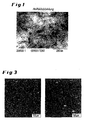
- the success of the dispersion was determined by transmission electron microscopy and is in illustration 1 shown.
- differential scanning calorimetry eg Mettler Toledo DSC 822 e according to manufacturer's instructions
- a melting temperature of 129.5 ° C was determined.
- the crystallinity of the sample was as in Macromol. Chem. 2001, (202), 2239-2246 described, calculated and amounted to 39%.
- Figure 1 shows a TEM image of a carbon nanotube / polyethylene mixture
- Example 5 Preparation of a Carbon Nanotube Polymer Composite from In-situ Polymerized Carbon Nanotube Polyethylene Masterbatch and High Density Polyethylene (HDPE)
- An in-situ polymerized carbon nanotube / polyethylene masterbatch with 13% by weight carbon nanotube portion was incorporated in a co-rotating twin-screw extruder into an HDPE (Lupolen 4261, Basell). Both the HDPE and the carbon nanotube polyethylene masterbatch were in powder form. 8% by weight of the masterbatch and 92% by weight of the HDPE were each conveyed via one metering balance in the main feed of the extruder, so that the carbon nanotube concentration in the end product was 1% by weight.
- the extruder used was a ZSK 26Mc from Coperion Werner & Pfleiderer with a length / diameter ratio of 36 (cf. Fig. 2 ).
- the total throughput was 16 kg / h at a speed of 250 min-1.
- the melting of the HDPE and the masterbatch polyethylene as well as the distributive and dispersive mixing of the carbon nanotubes into the HDPE melt took place.
- moisture was removed via a vent.
- Four strands were formed in a hole die, which were then cooled in a water bath and granulated with a strand granulator.
- Figure 2 shows the extruder assembly used in Example 5 for producing the carbon nanotube polyethylene-HDPE composite without limiting it.
- the quality of dispersion of the carbon nanotubes in the final product was determined by Confocal Laser Scanning Microscopy (CLSM) with fluorescence contrast (Confocal Laser Scanning Microscope (CLSM) Leica TCS SP2). Carbon nanotube agglomerates appear as black particles on CLSM images because they do not fluoresce. Figure 3 shows sections of two granules. No black particles are recognized, which means that the carbon nanotubes are completely dispersed and there are no undispersed particles.
Landscapes
- Chemical & Material Sciences (AREA)
- Health & Medical Sciences (AREA)
- Chemical Kinetics & Catalysis (AREA)
- Medicinal Chemistry (AREA)
- Polymers & Plastics (AREA)
- Organic Chemistry (AREA)
- Engineering & Computer Science (AREA)
- Nanotechnology (AREA)
- General Physics & Mathematics (AREA)
- Condensed Matter Physics & Semiconductors (AREA)
- Composite Materials (AREA)
- Materials Engineering (AREA)
- Crystallography & Structural Chemistry (AREA)
- Physics & Mathematics (AREA)
- Compositions Of Macromolecular Compounds (AREA)
- Polymerisation Methods In General (AREA)
- Addition Polymer Or Copolymer, Post-Treatments, Or Chemical Modifications (AREA)
- Transition And Organic Metals Composition Catalysts For Addition Polymerization (AREA)
- Polymerization Catalysts (AREA)
- Carbon And Carbon Compounds (AREA)
Description
- Die Erfindung betrifft ein neues Verfahren zur Herstellung von Polymer- Kohlenstoffnanoröhrchen-Mischungen mittels Gasphasenpolymerisation und in einer besonderen Ausführungsform des Verfahrens anschließende Dispergierung in einem Kohlenstoffnanoröhrchen-Polymer-Composite und insbesondere homogene Kohlenstoffnanoröhrchen-Polymer-Mischungen und Kohlenstoffnanoröhrchen-Polymer-Composites durch eine in-situ Gasphasenpolymerisation von Ethylen, Propylen, Buten, Butadien, Isopren und/oder Norbornen in Gegenwart von auf den Kohlenstoffnanoröhrchen geträgerten Katalysatoren bei Temperaturen im Bereich von 0 bis 300°C zu vorgenannten Kohlenstoffnanoröhrchen-Polymer-Mischungen bzw. Kohlenstoffnanoröhrchen-Kautschuk-Mischungen.
- Unter Kohlenstoffnanoröhrchen (CNT) werden im Rahmen dieser Erfindung hauptsächlich zylinderförmige Kohlenstoffröhren mit einem Durchmesser von 3 bis 150 nm, bevorzugt 3 bis 80 nm verstanden, die Länge beträgt ein Vielfaches, mindestens 100-faches, des Durchmessers. Diese Röhrchen bestehen aus Lagen geordneter Kohlenstoffatome und weisen einen in der Morphologie unterschiedlichen Kern auf. Diese Kohlenstoffnanoröhrchen werden in der Literatur beispielsweise auch als "carbon fibrils" oder "hollow carbon fibres" bezeichnet. Die beschriebenen Kohlenstoffnanoröhrchen haben aufgrund ihrer Dimensionen und ihrer besonderen Eigenschaften eine technische Bedeutung für die Herstellung von Kompositmaterialien. Wesentliche weitere Möglichkeiten liegen in Elektronik-, Energie- und weiteren Anwendungen.
- Durch Einbau von nano-Füllstoffen lassen sich anwendungstechnische Eigenschaften von Polymeren deutlich verbessern. Nach Walter et. al., Macromol. Sci., 1999, A 36, 1613, lassen sich Eigenschaftsverbesserungen schon bei sehr niedrigen nano-Füllstoffgehalten realisieren. Die Herstellung derartiger Nano-Füllstoff/Polymer-Mischungen lassen sich bspw. über Schmelzeeintragung, Eintragung über einem Polymerauflösungsvorgang oder über eine in-situ Polymerisation erreichen. Die letztere Methode bringt den Vorteil, dass nach der Polymerisation kein zusätzlicher Arbeitsvorgang zur Herstellung der Füllstoff/Polymer-Mischung notwendig ist.
- Die Herstellung von Kohlenstoffnanoröhrchen/Polyolefin- bzw. von Kohlenstoffnanoröhrchen /Polymere auf Basis von Diolefinen-Mischungen ist in der wissenschaftlichen und technischen Literatur bekannt.
- Wiemann et. al., Conference, IUPAC-Symposium Macro, 2004, Paris, sowie Bonduel et. al., Chem. Comm., 2005, 781-783, beschreiben die Herstellung von Kohlenstoffnanoröhrchen /Polypropylen-Mischungen mittels in-situ Polymerisation in Anwesenheit von Kohlenstoffnanoröhrchen. Bei der Polymerisation handelt es sich um eine Lösungspolymerisation, d.h. die Polymerisation wird in einem Lösungsmittel durchgeführt, wobei Katalysator (Zr-Metallocen) sowie Promotor (MAO) darin gelöst wurden. Diese Methode besitzt den Nachteil, dass eine energieintensive Entfernung des Lösungsmittels notwendig ist.
- In
WO 99/23287 A1 WO 01/10779 A1 - In
WO 95/07316 A1 - Die
WO 05/012170 - Die
US 2006/0057055 A1 beschreibt Verfahren zur "in-situ-Polymerisation" auf insbesondere Single-Wall-Carbon-Nano-Tubes, wobei diese in "Emulsion" oder "Mikro-Emulsion" ausgeführt werden. - Ebenso beschreibt die
KR 2005/060160 A - Die wenigen bis jetzt in der wissenschaftlichen und technischen Literatur bekannten Beispiele für die Herstellung homogener Kohlenstoffnanoröhrchen-Polyolefin- bzw. Kohlenstoffnanoröhrchen-Kautschuk-Mischungen zeichnen sich durch eine geringe Qualität der Mischungen aus bzw. es handelt sich um Verfahren die nicht in einer großtechnischen Produktion überführbar sind.
- Die Aufgabe der vorliegenden Erfindung bestand darin, ein Verfahren bereitzustellen, welches die Herstellung von Kohlenstoffnanoröhrchen-Polyolefin- bzw. Kohlenstoffnanoröhrchen-Kautschuk-Mischungen mittels in-situ Gasphasenpolymerisation ermöglicht. Insbesondere sollte eine breit anwendbare Methode gefunden werden, welche die Bildung homogener Mischungen aus Kohlenstoffnanoröhrchen und Polymer sicherstellt, sowie potentiell problematische bzw. technisch aufwendige Arten der Reaktionsführung sowie der Aufarbeitung vermeidet. Gleichzeitig sollte das Verfahren Vorteile hinsichtlich der Raum/Zeit-Ausbeute, der Handhabbarkeit, der Ökonomie und Ökologie im technischen Maßstab bringen.
- Überraschenderweise wurde nun gefunden, dass man homogene Kohlenstoffnanoröhrchen-Polymer-Mischungen bzw. Kohlenstoffnanoröhrchen-Kautschuk-Mischungen durch eine Gasphasenpolymerisation mit Hilfe von Kohlenstoffnanoröhrchen geträgerten Polymerisations-Katalysatoren herstellen kann.
- Gegenstand der Erfindung ist somit ein Verfahren zur Herstellung von homogenen Kohlenstoffnanoröhrchen-Polymer- bzw. Kohlenstoffnanoröhrchen-Kautschuk-Mischungen gemäß Anspruch 1.
- Die im erfindungsgemäßen Verfahren als Katalysatorträger bzw. als Füllstoff eingesetzten Kohlenstoffnanoröhrchen werden i. a. durch eine Abscheidung von kohlenstoffhaltigen gasförmigen Verbindungen aus der Gasphase an metallhaltigen Katalysatoren hergestellt. Als katalytische Metallkomponenten kommen eine Reihe von Übergangsmetalle wie z.B. Nickel, Eisen, Molybdän, Kobalt, Mangan, Kupfer, Chrom, Vanadium, Wolfram bzw. deren binäre, tertiäre, quaternäre usw. Mischungen wie bspw. in
WO 2006050903 A2 beschrieben in Frage. - Üblicherweise werden die auf Kohlenstoffnanoröhrchen geträgerten Katalysatoren (CNT-Katalysatoren) durch Zugabe des in einem trockenen Lösungsmittel, bspw. Toluol, Benzol, Heptan, Hexan, Cyclohexan gelösten Katalysators zur Kohlenstoffnanoröhrchen-Suspension und die Fixierung des Katalysators an den auf der Kohlenstoffnanoröhrchen-Oberfläche hergestellt. Anschließend wird die Herstellung des geträgerten CNT-Katalysators durch eine Abtrennung des Lösungsmittel, bspw. durch Verdampfen, vervollständigt.
- In einer besonderen Ausführungsform des erfindungsgemäßen Verfahrens werden die Kohlenstoffnanoröhrchen physikalisch oder chemisch behandelt. Insbesondere werden die Kohlenstoffnanoröhrchen üblicherweise entweder "gewaschen" oder mittels physikalische oder chemische Behandlung funktionalisiert. Die Wäsche der Kohlenstoffnanoröhrchen erfolgt bevorzugt durch die Einwirkung einer nichtoxidierenden anorganischen Säure, wie bspw. HCl. Durch diese Behandlung werden ungewünschte Verunreinigungen der Kohlenstoffnanoröhrchen aus dem Herstellprozess entfernt. Bei der Funktionalisierung der Kohlenstoffnanoröhrchen handelt es sich ganz bevorzugt, ohne sich darauf zu beschränken, um eine Sauerstoff-Funktionalisierung insbesondere durch Einbau von aciden Gruppen. Dieses kann beispielsweise durch die Einwirkung von flüssigen Oxidationsmitteln bzw. deren Mischungen als auch von gasförmigen Oxidationsmitteln erfolgen. Bevorzugt sind bspw. HNO3, H2SO4, H2O2, HClO4, O2, O3, CO2 usw., besonders bevorzugt HNO3 oder Mischungen HNO3 mit H2SO4. Die Anzahl der aciden Gruppen lässt sich durch Titration und/oder durch Röntgen-Photoelektronenspektroskopie (XPS) wie beispielsweise in M. Toebes, Carbon, (42), 2004, 307-315 beschrieben, bestimmen und liegt üblicherweise im Bereich von 50-10000 microÄquivalent/g (µäq/g) Kohlenstoffnanoröhrchen, bevorzugt im Bereich von 100-8000 µäq/g Kohlenstoffnanoröhrchen und ganz bevorzugt im Bereich von 250-5000 µäq/g Kohlenstoffnanoröhrchen.
- Für die koordinative Polymerisation von Olefinen, zu denen die erfindungsgemäß verwendeten Gase Ethylen, Propylen und Buten gehören, kommen die dem Fachmann bekannten üblichen Polymerisations-Katalysatoren, d. h. Übergangsmetall-Katalysatoren und Ziegler-Natta Katalysatoren in Frage.

- Eine Übersicht über eine Reihe dem Stand der Technik entsprechenden Metallocen-Katalysatoren wird von Kaminsky et. al., Appl. Cat. A.: Gen., 2002, 2001, 47-61 beschrieben. Als typische Polymerisations-Katalysatoren, ohne sich jedoch darauf zu beschränken, kommen bspw. folgende Übergangsmetallkatalysatoren in Frage:
- mit R = H, Methyl, Ethyl, Butyl, Neomenthyl usw.
- mit M = Zr, Hf und X = C2H4, Me2Si usw.

- mit M = Zr, Hf, X = Me2C, Ph2C, R = H, Ethyl, Butyl usw.
- Ferner eignen sich für die erfindungsgemäße Gasphasenpolymerisation der Olefine auch Spätübergangskatalysatoren, wie beispielsweise in Journal of the American Chemical Society (1995), 117(23), 6414-15 beschrieben, mit folgender Struktur:
- mit M = Ni, Pd, Co, Fe, L = Methyl, Ethyl, Butyl, R Methyl, Aryl, verbrückt usw.

- In einer besonderen Ausführungsform des Verfahrens wird neben dem Polymerisations-Katalysator auch mindestens ein Cokatalysator eingesetzt.
- Als Cokatalysator für die o. g. Katalysatoren wird üblicherweise Methylalumoxan (MAO) eingesetzt. Prinzipiell eignen sich als Cokatalysator aber auch andere Aluminium-Verbindungen (Al-Verbindungen) insbesondere Aluminiumalkyle wie z.B. Trimethylaluminium, Triisobutylaluminium, die ggf. durch eine in-situ Teilhydrolyse aktiviert werden können. Bei den erfindungsgemäßen Gasphasenpolymerisationen wird üblicherweise im Vergleich zum Katalysator ein Überschuss an Cokatalysator eingestellt. Insbesondere wird üblicherweise ein molares Verhältnis Cokatalysator/Katalysator insbesondere Al-Verbindungen/Metall von 10-500, bevorzugt 10-400 und ganz bevorzugt von 10-300 eingestellt.
- Für die Gasphasenpolymerisation und -copolymerisation der Diolefine Butadien, Isopren, Norbonen, werden üblicherweise Ziegler-Natta Katalysatoren auf Basis von Ni, Co, Ti, und Nd eingesetzt. Bevorzugt werden Katalysatoren auf Nd-Basis, da sie Polymere mit hohen cis-Anteil der Doppelbindungen ermöglichen. Üblicherweise können, ohne sich darauf zu beschränken, folgende Neodym-Verbindungen eingesetzt werden:
- Nd-versatat (Versatat techn. Mischung aus α,α-disubstituierten C10-Carbonsäuren), Ndneodecanoate, [Nd(C3H5)3]2, Nd(C3H5)3, Ndcp(C3H5)2, Nd(C3H5)3.
- Als Co-katalysatoren werden bei derartigen Systemen bspw. Diisobutylaluminiumhydrid (DIBAH), Triisobutylaluminium und Ethylalumiumsesquichlorid (EASC) eingesetzt.
- In einer besonderen Ausführungsform des erfindungsgemäßen Verfahrens ist mindestens ein Cokatalysator ebenfalls auf den Kohlenstoffnanoröhrchen geträgert.
- Die Herstellung des auf Kohlenstoffnanoröhrchen geträgerten Katalysatorsystems wird üblicherweise durch eine Reaktion des Kohlenstoffnanoröhrchen-Trägers mit den Cokatalysatoren (insbesondere Al-Verbindungen) gestartet. Dadurch wird eine Fixierung der Cokatalysatoren (insbesondere Al-Verbindungen) auf den Kohlenstoffnanoröhrchen erreicht. Bspw. kann diese Reaktion in Lösung erfolgen, wobei bevorzugt trockene, unpolare Lösungsmittel wie z.B. Toluol, Benzol, Heptan, Hexan oder Cyclohexan oder Mischungen davon eingesetzt werden. Die Reaktion wird üblicherweise in einem Reaktionsapparat durchgeführt, der eine intensive Mischung der Lösung und der Kohlenstoffnanoröhrchen, die üblicherweise dispergiert oder sogar als Agglomerate vorliegen können, gewährleistet. Die Mischung kann mittels Rührer aber auch mittels Dispergierung mit Düsen oder Strahlen erfolgen. Alternativ kann die Mischenergie in beliebiger Form, wie z.B. Ultraschall, eingebracht werden. Diese Reaktion kann bei Raumtemperatur aber auch bei erhöhten Temperaturen durchgeführt werden. Bevorzugt wird die Reaktion bei Temperaturen von 10-100°C und ganz bevorzugt bei Temperaturen von 20-60°C durchgeführt. Ist diese Reaktion beendet, so wird durch Zugabe des in einem trockenen Lösungsmittel, bspw. Toluol, Benzol, Heptan, Hexan, Cyclohexan gelösten Polymerisations-Katalysators zur Kohlenstoffnanoröhrchen/Cokatalysator-Suspension die Fixierung des Katalysators an den auf der Kohlenstoffnanoröhrchen-Oberfläche fixierten Cokatalysatoren (insbesondere Al-Verbindungen) durchgeführt. Anschließend wird die Herstellung des geträgerten Katalysators durch eine Abtrennung des Lösungsmittel, bspw. durch Verdampfen, vervollständigt. Als Produkt erhält man einen aktiven, auf Kohlenstoffnanoröhrchen geträgerten Gasphasenpolymerisationskatalysator. Üblicherweise beträgt der Cokatalysatoranteil bezogen auf Gesamtmasse 0,01-15 Gew.% , bevorzugt 0,05-12 Gew.% und ganz bevorzugt 0,1-10 Gew.%. Der Katalysatoranteil liegt im Bereich von 0,001-5 Gew.% und bevorzugt im Bereich von 0,005-3 Gew.%.
- Die Polymerisation wird durch Zugabe der gasförmigen Monomeren gemäß Anspruch 1 gestartet.
- Die Gasphasenpolymerisation kann in allen für die Gasphasenpolymerisation geeigneten Reaktoren durchgeführt werden. Beispielsweise eignen sich Wirbelschichtreaktoren, Rührkesselreaktoren, Festbettreaktoren usw.
- Die Polymerisationstemperatur wird im Grunde von der Kinetik der Polymerisation bestimmt und lediglich durch die apparativen Gegebenheiten (Wärmeübergang) sowie den Schmelzpunkt der Polymere begrenzt. Das Verfahren gemäß Anspruch 1 wird bevorzugt bei Temperaturen im Bereich von 20-200°C ausgerührt. Die Gasphasenpolymerisation wird bei dem höchstmöglichsten Druck durchgeführt, da hohe Partialdrücke von Olefinen zu hohen Produktivitäten führen. Der Reaktionsdruck ergibt sich aus den bei der entsprechenden Reaktionstemperatur sich einstellenden Dampfdruck der Monomere. Beispielsweise ohne sich darauf zu beschränken wird die in-situ Polymerisation von Ethylen bei einer Reaktionsdruck von 1 bar bis zu 200 bar, bevorzugt von 1 bis 100 bar durchgeführt. Die Umsetzung des Monomers aus der Gasphase kann diskontinuierlich erfolgen d.h. der Reaktionsdruck im Reaktor nimmt im Laufe der Reaktion ab. Eine andere Reaktionsführung wird durch eine konstante Nachdosierung des Monomers erreicht. Dadurch wird die in situ-Polymerisation bei einem konstanten Reaktionsdruck durchgeführt. Üblicherweise wird das erfindungsgemäße Verfahren in einem Reaktor unter Durchmischung des Reaktionsmaterial z.B. in einem Rührkessel mit drehenden Rührer durchgeführt.
- Der Prozentsatz an Polymer (insbesondere Polyethylen) in der Kohlenstoffnanoröhrchen-Polymer-Mischung bzw. Kohlenstoffnanoröhrchen-Kautschuk-Mischung ist je nach Reaktionszeit und Reaktionsdruck variabel.
- Überraschenderweise gelingt die erfindungsgemäße Umsetzung der Monomere an den spezifischen Kohlenstoffnanoröhrchen-Trägerkatalysatoren in ganz vorteilhafter Weise, wobei nur homogen verteilte Kohlenstoffnanoröhrchen-Polymer-Mischungen bzw. Kohlenstoffnanoröhrchen-Kautschuk-Mischungen erhalten werden. Diese Polymer- bzw. Kautschuk-Mischungen besitzen ganz bevorzugt Kohlenstoffnanoröhrchen-Anteile von 0,1-50 Gew.%, besonders bevorzugt von 0,1-30 Gew.%. Derartige Kohlenstoffnanoröhrchen-Polymermischungen bzw. Kohlenstoffnanoröhrchen-Kautschuk-Mischungen können direkt weiterverarbeitet werden, jedoch in bevorzugter Weise können sie auch als Masterbatch, d.h. als konzentrierter Polymer- bzw. Kautschuk-Füller Mischung, die anschließend mit einem zweiten Polymer verschnitten wird, eingesetzt werden. Derartige Kohlenstoffnanoröhrchen-Polymer bzw. Kautschuk-Masterbatch lassen sich mit anderen Polymeren wie z.B. Polyethylen, Polypropylen, Polyethylen-co-styrol, Polybutadien, Polyisopren, Polystyrol-co-acrylnitril, EPDM Polychloropren, Polyethylen-vinylacetate mit den üblichen Methoden, z.B. Lösungsmischung, Schmelzemischung mit Extrudern usw., in Kohlenstoffnanoröhrchen-Polymeren- bzw. Kohlenstoffnanoröhrchen-Kautschuk-Composites hervorragend mischen.
- Es gelingt durch die beschriebenen Verfahrensschritte, die Kohlenstoffnanoröhrchen, auch wenn diese ursprünglich in Form von Bündeln oder Agglomeraten vorliegen, voneinander zu trennen und homogen im Polymer zu verteilen.
- Der Erfolg der Dispergierung wird üblicherweise mittels Transmission-Elektronen-Mikroskop (TEM) (z.B. Philips/Fei tecnai 20 mit LaB6-Kathode, lxlk CCD-Kamera der Firma TVIPS "F 114T nach Anweisungen des Herstellers) bzw. alternativ mittels Confokaler Laser Scanning Mikroskopie (CLSM) mit Fluoreszenzkontrast (z.B. Confocal Laser Scanning Microscope Leica TCS SP2 nach Anweisungen des Herstellers) bestimmt. Nach beiden Methoden wird die Präsenz bzw. Abwesenheit von schwarzen Partikeln sichtbar, wobei die Abwesenheit von schwarzen Partikeln bedeutet, dass die Kohlenstoffnanoröhrchen vollständig dispergiert vorliegen und keine undispergierten Partikel vorhanden sind. Je nach Anteil an Kohlenstoffnanoröhrchen bzw. Polymer insbesondere Polyethylen können Kohlenstoffnanoröhrchen-Polymer-Mischungen bzw. Kohlenstoffnanoröhrchen-Polymer-Composites mit Schmelztemperaturen im Bereich von 100 bis 180°C bevorzugt 120 bis 150°C und / oder eine Kristallinität von 1 bis 50 % bevorzugt 5 bis 40% produziert werden.
- In einem Kolben mit Rührorgan und Kühler wurden 50 g Kohlenstoffnanoröhrchen (Baytubes, hergestellt wie in
WO 2006050903 beschrieben) und 1300 mL 37 % HCl vorgelegt. Anschließend wurde 1 h unter Rückfluss gekocht. Nach Abkühlen wurde mit H2O neutral gewaschen und im Vakuum bei 80°C über Nacht getrocknet. Die Ausbeute an gewaschenen Kohlenstoffnanoröhrchen betrug 98,7 %. - In einem Kolben mit Rührorgan und Kühler wurden 30 g CNT und 900 mL 70 % HNO3 vorgelegt. Anschließend wurde 5 h unter Rückfluss gekocht. Nach Abkühlen wurde mit H2O neutral gewaschen und im Vakuum über Nacht getrocknet. Die Ausbeute an funktionalisierten Kohlenstoffnanoröhrchen betrug 23,37 g (77,9 %). Die Anzahl der sauren Gruppen wurde mittels Titration bestimmt und beträgt 931 µäq/g COOH/g Kohlenstoffnanoröhrchen.
- In einem inertisierten Reaktor mit Rührer, Inertgaszuleitung, Gasblasenzähler, Destillationsbrücke, sowie Dosiereinheit von Flüssigkeiten unter Schutzgas wurden 45 g an Kohlenstoffnanoröhrchen aus Beispiel 1 vorgelegt. Anschließend wurden durch intensive Spülung mit Argon bei 120°C (Ölbad) 1 h lang möglicherweise vorhandene O2- bzw. H2O-Spuren entfernt. Nach Abkühlen auf Raumtemperatur wurden über eine vorher mit Inertgas intensiv gespülte Polyethylen-Schlauch-Verbindung zur geschlossenen Zugabe von "getrockneten" Lösungsmitteln/Chemikalien, 30,7 g MAO in Toluol sowie 116 mg (n-Bu-Cp)2ZrCl2 (Bu = Butyl, Cp = Cyclopentadienyl) in den Reaktor befördert. Die Kohlenstoffnanoröhrchen-Katalysatorsuspension wurde ca. 5 h intensiv gerührt und anschließend das Lösungsmittel abdestilliert.
- 45 g des im Beispiel 3 hergestellten Katalysators wurden in einem druckfesten Stahlautoklaven mit einem langsamdrehenden (300 U/min) Ankerrührer eingeführt und auf eine Reaktionstemperatur von 90°C aufgeheizt. Anschließend wurde durch die Einstellung von 10 bar Ethylen die Gasphasenpolymerisation gestartet. Die Polymerisation wurde bei konstantem Druck durchgeführt, da eine automatische Zugabe des verbrauchten Ethylens über das anlageneigene Regelsystem erfolgte. Nach der Zudosierung von 325 1 Ethylen (372 g Ethylen) wurde die Polymerisation durch Abkühlen abgebrochen. Erhalten wurden 324 g einer Kohlenstoffnanoröhrchen/Polyethylen-Mischung, was einem Massenanteil von 13.9% Kohlenstoffnanoröhrchen bezogen auf Polyethylen entspricht. Der Erfolg der Dispergierung wurde mittels Transmission Elektronen Mikroskopie bestimmt und ist in
Abbildung 1 dargestellt. Mittels Differential Scanning Calorimetry (z.B. Mettler Toledo DSC 822e nach Anweisungen des Herstellers) wurde eine Schmelztemperatur von 129,5°C bestimmt. Die Kristallinität der Probe wurde wie beispielsweise in Macromol. Chem. 2001, (202), 2239-2246 beschrieben, berechnet und betrug 39%. - Ein in-situ polymerisierter Kohlenstoffnanoröhrchen/Polyethylen Masterbatch mit 13 Gew.-% Kohlenstoffnanoröhrchen-Anteil wurde in einem gleichläufigen Doppelschneckenextruder in ein HDPE (Lupolen 4261, Fa. Basell) eingearbeitet. Sowohl das HDPE als auch der Kohlenstoffnanoröhrchen-Polyethylen-Masterbatch lagen in Pulverform vor. Es wurden 8 Gew.-% des Masterbatchs und 92 Gew.-% des HDPE über je eine Dosierwaage in der Haupteinzug des Extruders gefördert, so dass die Kohlenstoffnanoröhrchen -Konzentration im Endprodukt 1 Gew.-% betrug. Bei dem verwendeten Extruder handelte es sich um einen ZSK 26Mc von Coperion Werner & Pfleiderer mit einem Länge/Durchmesser-Verhältnis von 36 (vgl.
Abb. 2 ). Der Gesamtdurchsatz betrug 16 kg/h bei einer Drehzahl von 250 min-1. Im Extruder erfolgte die Aufschmelzung des HDPE und des Masterbatch-Polyethylens sowie das distributive und dispersive Mischen der Kohlenstoffnanoröhrchen in die HDPE-Schmelze. Im vorletzten Gehäuse wurde über eine Entlüftung Feuchtigkeit abgezogen. In einer Loch-Düse wurden 4 Stränge ausgeformt, die anschließend in einem Wasserbad abgekühlt und mit einem Stranggranulator granuliert wurden. -
Abbildung 2 zeigt den im Beispiel 5 verwendeten Extruderaufbau zur Herstellung des Kohlenstoffnanoröhrchen-Polyethylen-HDPE Composites ohne sich darauf zu begrenzen. - Die Dispergiergüte der Kohlenstoffnanoröhrchen im Endprodukt wurde mittels Confokaler Laser Scanning Mikroskopie (CLSM) mit Fluoreszenzkontrast (Confocal Laser Scanning Microscope (CLSM) Leica TCS SP2) bestimmt. Kohlenstoffnanoröhrchen-Agglomerate erscheinen auf CLSM-Bildern als schwarze Partikel, da sie nicht fluoreszieren.
Abbildung 3 zeigt Anschnitte zweier Granulate. Man erkennt keine schwarzen Partikel, was bedeutet, dass die Kohlenstoffnanoröhrchen vollständig dispergiert vorliegen und keine undispergierten Partikel vorhanden sind.
Claims (7)
- Verfahren zur Herstellung von Kohlenstoffnanoröhrchen-Polymer-Mischungen bzw. Kohlenstoffnanoröhrchen-Kautschuk-Mischungen durch eine in-situ Gasphasenpolymerisation, dadurch gekennzeichnet, dass ein Gas bestehend aus Ethylen, Propylen, Buten, Butadien, Isopren und/oder Norbornen in Gegenwart von auf den Kohlenstoffnanoröhrchen geträgerten Katalysatoren bei Temperaturen im Bereich von 0 bis 300°C zu vorgenannten Kohlenstoffnanoröhrchen-Polymer-Mischungen bzw. Kohlenstoffnanoröhrchen-Kautschuk-Mischungen umgesetzt wird.
- Verfahrens nach Anspruch 1, dadurch gekennzeichnet, dass die Kohlenstoffnanoröhrchen physikalisch oder chemisch behandelt sind.
- Verfahrens nach einem der Ansprüche 1 oder 2, dadurch gekennzeichnet, dass die Kohlenstoffnanoröhrchen einen Anteil an aciden Gruppen von 50-10000 mäq/g Kohlen stoffnanoröhrchen aufweisen.
- Verfahren nach einem der Ansprüche 1 bis 3, dadurch gekennzeichnet, dass mindestens ein Cokatalysator eingesetzt wird.
- Verfahren nach Anspruch 4, dadurch gekennzeichnet, dass im Vergleich zum Katalysator ein Überschuss an Cokatalysator, insbesondere ein molares Verhältnis Cokatalysator/Katalysator von 10-500 eingestellt.
- Verfahren nach einem der Ansprüche 4 oder 5, dadurch gekennzeichnet, dass mindestens ein Cokatalysator auf den Kohlenstoffnanoröhrchen geträgert ist.
- Verfahren nach einem der Ansprüche 4 bis 6, dadurch gekennzeichnet, dass der Cokatalysatoranteil bezogen auf Gesamtmasse 0,01-15 Gew.% beträgt.
Applications Claiming Priority (2)
| Application Number | Priority Date | Filing Date | Title |
|---|---|---|---|
| DE102006035773A DE102006035773A1 (de) | 2006-08-01 | 2006-08-01 | Verfahren zur Herstellung von Kohlenstoffnanorörchen-Polymer-Mischungen mittels Gasphasenpolymerisation |
| PCT/EP2007/006409 WO2008014894A1 (de) | 2006-08-01 | 2007-07-19 | Verfahren zur herstellung von kohlenstoffnanoröhrchen-polymer-mischungen mittels gasphasenpolymerisation |
Publications (2)
| Publication Number | Publication Date |
|---|---|
| EP2054448A1 EP2054448A1 (de) | 2009-05-06 |
| EP2054448B1 true EP2054448B1 (de) | 2010-12-22 |
Family
ID=38596403
Family Applications (1)
| Application Number | Title | Priority Date | Filing Date |
|---|---|---|---|
| EP07786181A Not-in-force EP2054448B1 (de) | 2006-08-01 | 2007-07-19 | Verfahren zur herstellung von kohlenstoffnanoröhrchen-polymer-mischungen mittels gasphasenpolymerisation |
Country Status (7)
| Country | Link |
|---|---|
| US (1) | US20080293853A1 (de) |
| EP (1) | EP2054448B1 (de) |
| JP (1) | JP2009545639A (de) |
| AT (1) | ATE492572T1 (de) |
| DE (2) | DE102006035773A1 (de) |
| TW (1) | TW200829605A (de) |
| WO (1) | WO2008014894A1 (de) |
Families Citing this family (13)
| Publication number | Priority date | Publication date | Assignee | Title |
|---|---|---|---|---|
| KR101470524B1 (ko) | 2009-06-30 | 2014-12-08 | 한화케미칼 주식회사 | 혼화성이 증대된 복합탄소소재 및 이의 연속적인 제조 방법 |
| DE102010033750A1 (de) | 2009-08-03 | 2011-12-01 | Daniel Roock | Verfahren zur Herstellung von Mikrofaser Vliesstoffen aus Polymeren unterschiedlicher Permittivität |
| CN102133634B (zh) * | 2010-01-22 | 2015-08-26 | 清华大学 | 碳纳米管金属粉末混合体及金属复合材料的制备方法 |
| KR101699580B1 (ko) | 2010-09-03 | 2017-01-24 | 세키스이가가쿠 고교가부시키가이샤 | 수지 복합 재료 및 수지 복합 재료의 제조 방법 |
| TWI448422B (zh) | 2011-09-14 | 2014-08-11 | Ind Tech Res Inst | 奈米碳管粉體與其形成方法、複合材料之形成方法 |
| CN103965389B (zh) * | 2014-05-13 | 2016-09-21 | 清华大学 | 碳纳米管-高分子复合材料的气相聚合生产方法及装置 |
| KR101799573B1 (ko) * | 2016-02-19 | 2017-11-20 | 금호석유화학 주식회사 | 전도성 수지 조성물 및 이를 이용한 플라스틱 성형품 |
| JP2018021117A (ja) * | 2016-08-03 | 2018-02-08 | 片野染革株式会社 | 導電性樹脂組成物 |
| CN109201117B (zh) * | 2017-07-06 | 2021-11-16 | 中国石油化工股份有限公司 | 一种负载型乙烯齐聚催化剂及其制备方法和应用 |
| JP7605612B2 (ja) * | 2020-10-28 | 2024-12-24 | 三井化学株式会社 | オレフィン重合用触媒およびオレフィン重合体の製造方法 |
| JP7579672B2 (ja) * | 2020-10-28 | 2024-11-08 | 三井化学株式会社 | オレフィン重合用触媒およびオレフィン重合体の製造方法 |
| JP7752515B2 (ja) * | 2021-01-08 | 2025-10-10 | 三井化学株式会社 | オレフィン重合用触媒およびオレフィン重合体の製造方法 |
| JP2023082368A (ja) * | 2021-12-02 | 2023-06-14 | 三菱エンジニアリングプラスチックス株式会社 | 樹脂組成物の製造方法 |
Family Cites Families (11)
| Publication number | Priority date | Publication date | Assignee | Title |
|---|---|---|---|---|
| US5057475A (en) * | 1989-09-13 | 1991-10-15 | Exxon Chemical Patents Inc. | Mono-Cp heteroatom containing group IVB transition metal complexes with MAO: supported catalyst for olefin polymerization |
| JPH07102120A (ja) | 1993-09-10 | 1995-04-18 | Hyperion Catalysis Internatl Inc | 炭素フィブリル含有ゴム組成物および空気入りタイヤ |
| US6113819A (en) | 1997-11-03 | 2000-09-05 | Hyperion Catalysis International, Inc. | Three dimensional interpenetrating networks of macroscopic assemblages of oriented carbon fibrils and organic polymers |
| US5968650A (en) * | 1997-11-03 | 1999-10-19 | Hyperion Catalysis International, Inc. | Three dimensional interpenetrating networks of macroscopic assemblages of randomly oriented carbon fibrils and organic polymers |
| US6872681B2 (en) * | 2001-05-18 | 2005-03-29 | Hyperion Catalysis International, Inc. | Modification of nanotubes oxidation with peroxygen compounds |
| EP1663864B1 (de) * | 2003-08-05 | 2009-04-08 | Nanocyl S.A. | Auf polymer basierende verbundwerkstoffe mit kohlenstoffnanoröhren als füllstoff, herstellungsverfahren dafür und verwendungen davon |
| KR100590138B1 (ko) | 2003-12-15 | 2006-06-15 | 한국과학기술연구원 | 탄소나노튜브가 균일하게 분산된 내마모성 초고분자량폴리에틸렌 복합체 및 그의 제조 방법 |
| EP1694891B1 (de) | 2003-12-15 | 2010-06-09 | Daniel E. Resasco | Rheniumkatalysatoren und verfahren zur herstellung von einwandigen kohlenstoffnanoröhren |
| DE102004054959A1 (de) | 2004-11-13 | 2006-05-18 | Bayer Technology Services Gmbh | Katalysator zur Herstellung von Kohlenstoffnanoröhrchen durch Zersetzung von gas-förmigen Kohlenverbindungen an einem heterogenen Katalysator |
| JP2006176601A (ja) * | 2004-12-21 | 2006-07-06 | Bussan Nanotech Research Institute Inc | 重合触媒、それを用いて得られた重合体、およびその高分子複合体 |
| WO2008082426A1 (en) * | 2006-02-13 | 2008-07-10 | The Board Of Regents Of The University Of Oklahoma | Methods of making polymer composites containing single- walled carbon nanotubes |
-
2006
- 2006-08-01 DE DE102006035773A patent/DE102006035773A1/de not_active Withdrawn
-
2007
- 2007-07-19 JP JP2009522137A patent/JP2009545639A/ja active Pending
- 2007-07-19 AT AT07786181T patent/ATE492572T1/de active
- 2007-07-19 DE DE502007006048T patent/DE502007006048D1/de active Active
- 2007-07-19 EP EP07786181A patent/EP2054448B1/de not_active Not-in-force
- 2007-07-19 WO PCT/EP2007/006409 patent/WO2008014894A1/de not_active Ceased
- 2007-07-30 US US11/830,133 patent/US20080293853A1/en not_active Abandoned
- 2007-07-31 TW TW096127882A patent/TW200829605A/zh unknown
Also Published As
| Publication number | Publication date |
|---|---|
| JP2009545639A (ja) | 2009-12-24 |
| EP2054448A1 (de) | 2009-05-06 |
| TW200829605A (en) | 2008-07-16 |
| ATE492572T1 (de) | 2011-01-15 |
| WO2008014894A1 (de) | 2008-02-07 |
| DE102006035773A1 (de) | 2008-02-07 |
| DE502007006048D1 (de) | 2011-02-03 |
| US20080293853A1 (en) | 2008-11-27 |
Similar Documents
| Publication | Publication Date | Title |
|---|---|---|
| EP2054448A1 (de) | Verfahren zur herstellung von kohlenstoffnanoröhrchen-polymer-mischungen mittels gasphasenpolymerisation | |
| DE3752331T2 (de) | Verfahren zur Verbesserung der Effektivität eines prepolymerisierten Katalysators | |
| DE3022738C2 (de) | Verfahren zur Polymerisation eines α-Olefins mit 2 bis 6 Kohlenstoffatomen sowie zu deren Copolymerisation untereinander und/oder mit bis zu 5 Molprozent eines Diolefins | |
| DE69616510T2 (de) | Synthese von kautschukpolymeren in der dampfphase | |
| AT394855B (de) | Verfahren zur herstellung von katalysatorkomponenten zur polymerisation von olefinen | |
| DE1769130C3 (de) | Verfahren zur Herstellung von Kunststoffdispersionen und von Kunststoffen mit verbesserter Schlagfestigkeit | |
| DD245200A5 (de) | Verfahren zur herstellung von 1,4-cis-polybutadien | |
| DE60102128T2 (de) | Polybutenharz und Rohrwerkstoff und Rohr, das diesen Werkstoff enthält | |
| DE69604406T2 (de) | Kontroliertes degradierungsverfahren für polymerkohlenwasserstoffe. | |
| DE2728577A1 (de) | Verfahren zur durchfuehrung einer nichtwaessrigen dispersionspolymerisation eines konjugierten diolefinmonomeren | |
| DE69809531T2 (de) | Bestandteile und katalysatoren für die olefinpolymerisation | |
| EP1224230B1 (de) | Verfahren zur herstellung hochreaktiver polyisobutene | |
| DE10392773T5 (de) | Eine feste Katalysatorkomponente für die Polymerisation von Ethylen, Herstellung derselben und ein Katalysator diese enthaltend | |
| DE102013221849A1 (de) | Verfahren zur Herstellung eines Propylenpolymers | |
| EP2285874A1 (de) | Kohlenstoffnanoröhren und mikrogele enthaltende organische medien | |
| EP2496628A1 (de) | Verfahren zur herstellung einer wässrigen polymerisatdispersion | |
| DE2654940A1 (de) | Polymerisationsverfahren | |
| DE19512127A1 (de) | Neuer Katalysator für die Gasphasenpolymerisation von konjugierten Dienen | |
| DE2855383C2 (de) | Verfahren zur Herstellung eines Titantrichlorid-Katalysatorbestandteils | |
| DE69315266T2 (de) | Katalysator und Verfahren für Olefinpolymerisation | |
| DE102013015417A1 (de) | Propylenharzmaterial und Verfahren zu dessen Herstellung | |
| DE602005001852T2 (de) | Olefinpolymerisationsverfahren in gegenwart eines antifoulingmittels | |
| DE19753135A1 (de) | Aluminiumalkylkomplexe als Cokatalysatoren | |
| EP0370372B1 (de) | Verfahren zur kontinuierlichen Herstellung von Katalysatoren für die Niederdruckpolymerisation von Olefinen | |
| DE1294655B (de) | Verfahren zur Herstellung von Polyolefinen |
Legal Events
| Date | Code | Title | Description |
|---|---|---|---|
| PUAI | Public reference made under article 153(3) epc to a published international application that has entered the european phase |
Free format text: ORIGINAL CODE: 0009012 |
|
| 17P | Request for examination filed |
Effective date: 20090302 |
|
| AK | Designated contracting states |
Kind code of ref document: A1 Designated state(s): AT BE BG CH CY CZ DE DK EE ES FI FR GB GR HU IE IS IT LI LT LU LV MC MT NL PL PT RO SE SI SK TR |
|
| AX | Request for extension of the european patent |
Extension state: AL BA HR MK RS |
|
| 17Q | First examination report despatched |
Effective date: 20090907 |
|
| RAP1 | Party data changed (applicant data changed or rights of an application transferred) |
Owner name: BAYER TECHNOLOGY SERVICES GMBH |
|
| GRAP | Despatch of communication of intention to grant a patent |
Free format text: ORIGINAL CODE: EPIDOSNIGR1 |
|
| DAX | Request for extension of the european patent (deleted) | ||
| GRAS | Grant fee paid |
Free format text: ORIGINAL CODE: EPIDOSNIGR3 |
|
| GRAA | (expected) grant |
Free format text: ORIGINAL CODE: 0009210 |
|
| AK | Designated contracting states |
Kind code of ref document: B1 Designated state(s): AT BE BG CH CY CZ DE DK EE ES FI FR GB GR HU IE IS IT LI LT LU LV MC MT NL PL PT RO SE SI SK TR |
|
| REG | Reference to a national code |
Ref country code: GB Ref legal event code: FG4D Free format text: NOT ENGLISH |
|
| REG | Reference to a national code |
Ref country code: CH Ref legal event code: EP |
|
| REG | Reference to a national code |
Ref country code: IE Ref legal event code: FG4D |
|
| REF | Corresponds to: |
Ref document number: 502007006048 Country of ref document: DE Date of ref document: 20110203 Kind code of ref document: P |
|
| REG | Reference to a national code |
Ref country code: DE Ref legal event code: R096 Ref document number: 502007006048 Country of ref document: DE Effective date: 20110203 |
|
| REG | Reference to a national code |
Ref country code: NL Ref legal event code: T3 |
|
| PG25 | Lapsed in a contracting state [announced via postgrant information from national office to epo] |
Ref country code: LT Free format text: LAPSE BECAUSE OF FAILURE TO SUBMIT A TRANSLATION OF THE DESCRIPTION OR TO PAY THE FEE WITHIN THE PRESCRIBED TIME-LIMIT Effective date: 20101222 |
|
| LTIE | Lt: invalidation of european patent or patent extension |
Effective date: 20101222 |
|
| PG25 | Lapsed in a contracting state [announced via postgrant information from national office to epo] |
Ref country code: LV Free format text: LAPSE BECAUSE OF FAILURE TO SUBMIT A TRANSLATION OF THE DESCRIPTION OR TO PAY THE FEE WITHIN THE PRESCRIBED TIME-LIMIT Effective date: 20101222 Ref country code: SI Free format text: LAPSE BECAUSE OF FAILURE TO SUBMIT A TRANSLATION OF THE DESCRIPTION OR TO PAY THE FEE WITHIN THE PRESCRIBED TIME-LIMIT Effective date: 20101222 Ref country code: FI Free format text: LAPSE BECAUSE OF FAILURE TO SUBMIT A TRANSLATION OF THE DESCRIPTION OR TO PAY THE FEE WITHIN THE PRESCRIBED TIME-LIMIT Effective date: 20101222 Ref country code: BG Free format text: LAPSE BECAUSE OF FAILURE TO SUBMIT A TRANSLATION OF THE DESCRIPTION OR TO PAY THE FEE WITHIN THE PRESCRIBED TIME-LIMIT Effective date: 20110322 Ref country code: SE Free format text: LAPSE BECAUSE OF FAILURE TO SUBMIT A TRANSLATION OF THE DESCRIPTION OR TO PAY THE FEE WITHIN THE PRESCRIBED TIME-LIMIT Effective date: 20101222 Ref country code: CY Free format text: LAPSE BECAUSE OF FAILURE TO SUBMIT A TRANSLATION OF THE DESCRIPTION OR TO PAY THE FEE WITHIN THE PRESCRIBED TIME-LIMIT Effective date: 20101222 |
|
| REG | Reference to a national code |
Ref country code: IE Ref legal event code: FD4D |
|
| PG25 | Lapsed in a contracting state [announced via postgrant information from national office to epo] |
Ref country code: CZ Free format text: LAPSE BECAUSE OF FAILURE TO SUBMIT A TRANSLATION OF THE DESCRIPTION OR TO PAY THE FEE WITHIN THE PRESCRIBED TIME-LIMIT Effective date: 20101222 Ref country code: ES Free format text: LAPSE BECAUSE OF FAILURE TO SUBMIT A TRANSLATION OF THE DESCRIPTION OR TO PAY THE FEE WITHIN THE PRESCRIBED TIME-LIMIT Effective date: 20110402 Ref country code: EE Free format text: LAPSE BECAUSE OF FAILURE TO SUBMIT A TRANSLATION OF THE DESCRIPTION OR TO PAY THE FEE WITHIN THE PRESCRIBED TIME-LIMIT Effective date: 20101222 Ref country code: IS Free format text: LAPSE BECAUSE OF FAILURE TO SUBMIT A TRANSLATION OF THE DESCRIPTION OR TO PAY THE FEE WITHIN THE PRESCRIBED TIME-LIMIT Effective date: 20110422 Ref country code: PT Free format text: LAPSE BECAUSE OF FAILURE TO SUBMIT A TRANSLATION OF THE DESCRIPTION OR TO PAY THE FEE WITHIN THE PRESCRIBED TIME-LIMIT Effective date: 20110422 Ref country code: GR Free format text: LAPSE BECAUSE OF FAILURE TO SUBMIT A TRANSLATION OF THE DESCRIPTION OR TO PAY THE FEE WITHIN THE PRESCRIBED TIME-LIMIT Effective date: 20110323 |
|
| PG25 | Lapsed in a contracting state [announced via postgrant information from national office to epo] |
Ref country code: SK Free format text: LAPSE BECAUSE OF FAILURE TO SUBMIT A TRANSLATION OF THE DESCRIPTION OR TO PAY THE FEE WITHIN THE PRESCRIBED TIME-LIMIT Effective date: 20101222 Ref country code: PL Free format text: LAPSE BECAUSE OF FAILURE TO SUBMIT A TRANSLATION OF THE DESCRIPTION OR TO PAY THE FEE WITHIN THE PRESCRIBED TIME-LIMIT Effective date: 20101222 Ref country code: RO Free format text: LAPSE BECAUSE OF FAILURE TO SUBMIT A TRANSLATION OF THE DESCRIPTION OR TO PAY THE FEE WITHIN THE PRESCRIBED TIME-LIMIT Effective date: 20101222 |
|
| PLBE | No opposition filed within time limit |
Free format text: ORIGINAL CODE: 0009261 |
|
| STAA | Information on the status of an ep patent application or granted ep patent |
Free format text: STATUS: NO OPPOSITION FILED WITHIN TIME LIMIT |
|
| PG25 | Lapsed in a contracting state [announced via postgrant information from national office to epo] |
Ref country code: IE Free format text: LAPSE BECAUSE OF FAILURE TO SUBMIT A TRANSLATION OF THE DESCRIPTION OR TO PAY THE FEE WITHIN THE PRESCRIBED TIME-LIMIT Effective date: 20101222 Ref country code: DK Free format text: LAPSE BECAUSE OF FAILURE TO SUBMIT A TRANSLATION OF THE DESCRIPTION OR TO PAY THE FEE WITHIN THE PRESCRIBED TIME-LIMIT Effective date: 20101222 |
|
| 26N | No opposition filed |
Effective date: 20110923 |
|
| PG25 | Lapsed in a contracting state [announced via postgrant information from national office to epo] |
Ref country code: IT Free format text: LAPSE BECAUSE OF FAILURE TO SUBMIT A TRANSLATION OF THE DESCRIPTION OR TO PAY THE FEE WITHIN THE PRESCRIBED TIME-LIMIT Effective date: 20101222 Ref country code: MT Free format text: LAPSE BECAUSE OF FAILURE TO SUBMIT A TRANSLATION OF THE DESCRIPTION OR TO PAY THE FEE WITHIN THE PRESCRIBED TIME-LIMIT Effective date: 20101222 |
|
| REG | Reference to a national code |
Ref country code: DE Ref legal event code: R097 Ref document number: 502007006048 Country of ref document: DE Effective date: 20110923 |
|
| PG25 | Lapsed in a contracting state [announced via postgrant information from national office to epo] |
Ref country code: MC Free format text: LAPSE BECAUSE OF NON-PAYMENT OF DUE FEES Effective date: 20110731 |
|
| REG | Reference to a national code |
Ref country code: CH Ref legal event code: PL |
|
| PG25 | Lapsed in a contracting state [announced via postgrant information from national office to epo] |
Ref country code: LI Free format text: LAPSE BECAUSE OF NON-PAYMENT OF DUE FEES Effective date: 20110731 Ref country code: CH Free format text: LAPSE BECAUSE OF NON-PAYMENT OF DUE FEES Effective date: 20110731 |
|
| REG | Reference to a national code |
Ref country code: DE Ref legal event code: R081 Ref document number: 502007006048 Country of ref document: DE Owner name: BAYER INTELLECTUAL PROPERTY GMBH, DE Free format text: FORMER OWNER: BAYER TECHNOLOGY SERVICES GMBH, 51373 LEVERKUSEN, DE Effective date: 20130226 |
|
| PG25 | Lapsed in a contracting state [announced via postgrant information from national office to epo] |
Ref country code: LU Free format text: LAPSE BECAUSE OF NON-PAYMENT OF DUE FEES Effective date: 20110719 |
|
| REG | Reference to a national code |
Ref country code: AT Ref legal event code: MM01 Ref document number: 492572 Country of ref document: AT Kind code of ref document: T Effective date: 20120731 |
|
| REG | Reference to a national code |
Ref country code: NL Ref legal event code: SD Effective date: 20130913 |
|
| PG25 | Lapsed in a contracting state [announced via postgrant information from national office to epo] |
Ref country code: TR Free format text: LAPSE BECAUSE OF FAILURE TO SUBMIT A TRANSLATION OF THE DESCRIPTION OR TO PAY THE FEE WITHIN THE PRESCRIBED TIME-LIMIT Effective date: 20101222 |
|
| PG25 | Lapsed in a contracting state [announced via postgrant information from national office to epo] |
Ref country code: AT Free format text: LAPSE BECAUSE OF NON-PAYMENT OF DUE FEES Effective date: 20120731 Ref country code: HU Free format text: LAPSE BECAUSE OF FAILURE TO SUBMIT A TRANSLATION OF THE DESCRIPTION OR TO PAY THE FEE WITHIN THE PRESCRIBED TIME-LIMIT Effective date: 20101222 |
|
| PGFP | Annual fee paid to national office [announced via postgrant information from national office to epo] |
Ref country code: DE Payment date: 20130717 Year of fee payment: 7 Ref country code: NL Payment date: 20130716 Year of fee payment: 7 Ref country code: BE Payment date: 20130712 Year of fee payment: 7 |
|
| PGFP | Annual fee paid to national office [announced via postgrant information from national office to epo] |
Ref country code: FR Payment date: 20130724 Year of fee payment: 7 Ref country code: GB Payment date: 20130717 Year of fee payment: 7 |
|
| REG | Reference to a national code |
Ref country code: GB Ref legal event code: 732E Free format text: REGISTERED BETWEEN 20140102 AND 20140108 |
|
| REG | Reference to a national code |
Ref country code: DE Ref legal event code: R119 Ref document number: 502007006048 Country of ref document: DE |
|
| REG | Reference to a national code |
Ref country code: NL Ref legal event code: V1 Effective date: 20150201 |
|
| GBPC | Gb: european patent ceased through non-payment of renewal fee |
Effective date: 20140719 |
|
| PG25 | Lapsed in a contracting state [announced via postgrant information from national office to epo] |
Ref country code: NL Free format text: LAPSE BECAUSE OF NON-PAYMENT OF DUE FEES Effective date: 20150201 |
|
| REG | Reference to a national code |
Ref country code: FR Ref legal event code: ST Effective date: 20150331 |
|
| PG25 | Lapsed in a contracting state [announced via postgrant information from national office to epo] |
Ref country code: DE Free format text: LAPSE BECAUSE OF NON-PAYMENT OF DUE FEES Effective date: 20150203 |
|
| REG | Reference to a national code |
Ref country code: DE Ref legal event code: R119 Ref document number: 502007006048 Country of ref document: DE Effective date: 20150203 |
|
| PG25 | Lapsed in a contracting state [announced via postgrant information from national office to epo] |
Ref country code: FR Free format text: LAPSE BECAUSE OF NON-PAYMENT OF DUE FEES Effective date: 20140731 Ref country code: GB Free format text: LAPSE BECAUSE OF NON-PAYMENT OF DUE FEES Effective date: 20140719 |
|
| REG | Reference to a national code |
Ref country code: FR Ref legal event code: TP Owner name: BAYER INTELLECTUAL PROPERTY GMBH, DE Effective date: 20151126 |
|
| PG25 | Lapsed in a contracting state [announced via postgrant information from national office to epo] |
Ref country code: BE Free format text: LAPSE BECAUSE OF NON-PAYMENT OF DUE FEES Effective date: 20140731 |