EP2055920A2 - Abstandssperrmechanismus - Google Patents
Abstandssperrmechanismus Download PDFInfo
- Publication number
- EP2055920A2 EP2055920A2 EP08018507A EP08018507A EP2055920A2 EP 2055920 A2 EP2055920 A2 EP 2055920A2 EP 08018507 A EP08018507 A EP 08018507A EP 08018507 A EP08018507 A EP 08018507A EP 2055920 A2 EP2055920 A2 EP 2055920A2
- Authority
- EP
- European Patent Office
- Prior art keywords
- cover
- engine
- cylinder head
- blocking member
- gap
- Prior art date
- Legal status (The legal status is an assumption and is not a legal conclusion. Google has not performed a legal analysis and makes no representation as to the accuracy of the status listed.)
- Granted
Links
Images




Classifications
-
- F—MECHANICAL ENGINEERING; LIGHTING; HEATING; WEAPONS; BLASTING
- F02—COMBUSTION ENGINES; HOT-GAS OR COMBUSTION-PRODUCT ENGINE PLANTS
- F02F—CYLINDERS, PISTONS OR CASINGS, FOR COMBUSTION ENGINES; ARRANGEMENTS OF SEALINGS IN COMBUSTION ENGINES
- F02F7/00—Casings, e.g. crankcases
- F02F7/006—Camshaft or pushrod housings
-
- F—MECHANICAL ENGINEERING; LIGHTING; HEATING; WEAPONS; BLASTING
- F02—COMBUSTION ENGINES; HOT-GAS OR COMBUSTION-PRODUCT ENGINE PLANTS
- F02B—INTERNAL-COMBUSTION PISTON ENGINES; COMBUSTION ENGINES IN GENERAL
- F02B77/00—Component parts, details or accessories, not otherwise provided for
- F02B77/11—Thermal or acoustic insulation
Definitions
- the present invention relates to a gap blocking mechanism that is disposed in an engine compartment of a motor vehicle or the like.
- An engine cover is disposed in an engine compartment of a motor vehicle.
- a cylinder head cover is disposed at a given distance under the engine cover.
- the cylinder head cover covers a cylinder head of the engine.
- one more cover may be disposed on the cylinder head cover.
- a cover for a cylinder head cover By providing such cover for a cylinder head cover, engine noise can be reduced. There is a gap between the cover for a cylinder head cover and the engine cover.
- a space under the back side of a bonnet panel in the engine compartment is often provided from a viewpoint of securing a space for pedestrian protection in the event of a collision.
- the centre of gravity of the engine tends to be located behind front wheels (at a passenger compartment side).
- a space for the engine compartment itself tends to be smaller due to expansion of a space for the passenger compartment.
- members that are relatively sensitive to heat such as hoses and harnesses, and members that can have high temperatures, such as a turbocharger and exhaust manifold, may be closely arranged at the front and rear sides of the gap between the cover for a cylinder head cover and the engine cover, respectively.
- a heat shield that is an extension of the cylinder head cover is disclosed in Japanese Utility Model Application Publication No. JP-U-06-40312 .
- the heat shield disclosed in Japanese Utility Model Application Publication No. JP-U-06-40312 allows protecting a sealing gasket from heat generated by the exhaust manifold.
- JP-U-63-60009 Disclosed in Japanese Utility Model Application Publication No. JP-U-63-60009 is a protective cover attached to the cylinder head cover.
- the protective cover disclosed in Japanese Utility Model Application Publication No. JP-U-63-60009 allows protecting devices around the exhaust manifold from heat generated thereby.
- the soundproof cover disclosed in Japanese Patent Application Publication No. JP-A-2005-264790 includes a heat insulation part.
- the heat insulation part allows protecting a sound absorbing member from heat generated by the exhaust manifold.
- JP-U-06-40312 the protective cover disclosed in Japanese Utility Model Application Publication No. JP-U-63-60009 , or the heat insulation part disclosed in Japanese Patent Application Publication No. JP-A-2005-264790 , therefore, may generate noise, such as vibrational noise. It is also impossible to block an air flow around the free end, which tends to cause insufficient heat insulation.
- the present invention has been devised in view of the above problems.
- a gap blocking mechanism for protecting a member to be protected from heat generated by a heat source includes: an engine cover; a cover for a cylinder head cover that is disposed on a front side of a cylinder head cover disposed at a predetermined distance from a back side of the engine cover; and a blocking member that blocks at least a part of a gap between the engine cover and the cover for a cylinder head cover, and that is formed integrally with any one of the engine cover and the cover for a cylinder head cover and elastically contacted with an elastic member included in the other thereof using elastic contact force of the elastic member.
- the blocking member is provided between the heat source on one side and the member to be protected on the other side.
- the blocking member is disposed in the gap between the engine cover and the cover for a cylinder head cover of the gap blocking mechanism according to the first aspect of the present invention.
- the blocking member extends between the heat source and the member to be protected. Therefore, the member to be protected can be protected from heat generated by the heat source.
- the blocking member is formed integrally with any one of the engine cover and the cover for a cylinder head cover. Therefore, the number of components can be reduced compared to a case in which the blocking member is formed separately.
- the other of the engine cover and the cover for a cylinder head cover (which is not formed integrally with the blocking member) includes an elastic member.
- the blocking member is in elastic contact with the elastic member. Therefore, vibrations of the blocking member can be reduced. Accordingly, it is possible to reduce generation of noise, such as vibrational noise.
- the blocking member is in elastic contact with the elastic member, no gap is formed between the blocking member and the elastic member. Therefore, an air flow passing through the gap between the blocking member and elastic member can be reduced. Accordingly, better heat insulation is provided by the gap blocking mechanism according to the first aspect of the present invention.
- a sound source is arranged on one side and a passenger compartment be arranged on the other side with the blocking member therebetween. With this configuration, noise transmission from the sound source to the passenger compartment can be reduced.
- a burial depth of the blocking member into the elastic member when the blocking member is in elastic contact with the elastic member can be determined by a mechanism for mounting the engine cover.
- the burial depth can be determined according to a vehicle model without any limitations.
- elastic contact force may be determined for an individual vehicle model without any restrictions.
- the burial depth can be made uniform among multiple vehicles of the same model. In other words, variation in heat insulation performance can be reduced among vehicles of the same model.
- the blocking member extends in a direction intersecting with a direction in which the heat source and the member to be protected are disposed and a bent portion is arranged in at least a part of the blocking member.
- bent portion means a portion that is not in the shape of a straight line.
- the "bent portion” includes a curved portion or an angled portion.
- the blocking member it is possible to make the blocking member to be elastically contacted with the elastic member by stronger elastic contact force compared to a case in which the blocking member is in the shape of a straight line. Accordingly, it is possible to reduce noise generated from the blocking member in more reliable manner. Better heat insulation is also provided due to the stronger elastic contact force.
- the bent portion increases the rigidity of the blocking member itself, thereby reducing vibrations of the blocking member. Accordingly, it is possible to further reduce noise generated from the blocking member itself.
- the elastic member is disposed on the back side of the engine cover and the blocking member is formed integrally with the cover for a cylinder head cover.
- a variety of adjacent components are disposed around the engine. It is, therefore, necessary to secure a stroke for mounting so that the engine cover does not interfere with adjacent components when the engine cover is mounted. If the blocking member is formed integrally with the engine cover, a stroke for the blocking member has to be secured in addition to the stroke for mounting.
- the blocking member is formed integrally with the cover for a cylinder head cover. It is, therefore, unnecessary to secure a stroke for the blocking member in mounting the engine cover. This facilitates the process for mounting the engine cover. It is also unnecessary to modify the configuration of the engine cover in order to secure a stroke for the blocking member. This increases degree of flexibility in design of the engine cover, and enables reduction in costs of manufacturing the engine cover.
- a sound absorbing member that has elasticity may be disposed on the back side of the engine cover beforehand.
- the sound absorbing member is also used as the elastic member used in this configuration, the number of components is reduced.
- the cover for a cylinder head cover, the blocking member, and the engine cover are arranged in this order from the nearest to the engine. In ascending order of heat resistance required of each member, therefore, firstly comes the cover for a cylinder head cover, secondly the blocking member, and lastly the engine cover. Accordingly, if the blocking member is formed integrally with the engine cover, not only the blocking member but also the engine cover must be made of a material that is more heat-resistant than the conventional material.
- the blocking member is formed integrally with the cover for a cylinder head cover. It is, therefore, unnecessary to manufacture the engine cover with a material having high heat resistance. This enables reduction in costs of manufacturing the engine cover. This also makes it possible to dispose the blocking member having high heat resistance only by making small modifications in design of the existing cover for a cylinder head cover.
- an attachment portion to which the member to be protected is attached is integrally formed on the cover for a cylinder head cover, with the blocking member interposed between the attachment portion and the heat source.
- the number of components can be reduced compared to a case in which the attachment portion is formed separately from the cover for a cylinder head cover. It is also possible to protect the member to be protected from heat generated by the heat source in more reliable manner.
- the member to be protected is a member to be routed, such as hoses and harnesses.
- a routing path can be set such that the member to be routed can be protected from heat generated by the heat source.
- FIG. 1 is a top view of the gap blocking mechanism according to the first embodiment.
- FIG. 2 is a sectional view taken along line II-II of FIG. 1 .
- FIG. 2 also shows adjacent members.
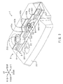
- FIG. 3 is a perspective view of the gap blocking mechanism.
- FIG. 4 is an exploded perspective view of the gap blocking mechanism.
- a gap blocking mechanism 1 is disposed in an engine compartment 90 of the vehicle, as shown in FIGS. 1 to 4 . Disposed behind the engine compartment 90 is a passenger compartment (not shown).
- the gap blocking mechanism 1 includes an engine cover 2, a cover 3 for a cylinder head cover and a blocking member 4.
- the engine cover 2 is disposed under a bonnet panel 91.
- the engine cover 2 covers a diesel engine 92 from above.
- the engine cover 2 is removably mounted on the diesel engine 92 by a bolt-and-nut mechanism.
- bolts are provided at a predetermined position of an upper surface of the diesel engine 92 so as to protrude.
- bolt through holes are provided at a predetermined position of the engine cover 2, facing the bolts. The bolts are correspondingly inserted in the bolt through holes and nuts (not shown) are screwed onto respective ends of the bolts so that the engine cover 2 is attached to the diesel engine 92.
- the engine cover 2 includes a cover body 20 and a sound absorbing member 21.
- the sound absorbing member 21 is included in an elastic member according to the present invention.
- the cover body 20 is made of ABS (a copolymer of acrylonitrile, styrene, and butadiene) resin, having the shape of a shallow rectangular tray whose open end faces downwards. Formed in the cover body 20 are holes 200 and 201.
- the sound absorbing member 21 is formed integrally with the cover body 20 by foam moulding.
- the cover 3 for a cylinder head cover is disposed at a predetermined distance under the engine cover 2.
- the cover 3 for a cylinder head cover covers a cylinder head cover 920 of the diesel engine 92 from above.
- FIG. 5 is an enlarged view of the inside of the circle V shown in FIG. 2 .
- the cover 3 for a cylinder head cover includes a cover body 30, a sound absorbing member 31, an attachment portion 32, and a boss 33, as shown in FIGS. 3 to 5 .
- the cover body 30 is made of polyamide (PA), having a shape of a long, narrow, shallow tray whose open end faces downwards.
- the attachment portion 32 is disposed on the upper surface of the cover body 30.
- the attachment portion 32 is formed integrally with the cover body 30.
- the attachment portion 32 includes a concave 320 for a hose and a concave 321 for a harness. Both the concave 320 for a hose and the concave 321 for a harness have a C shape whose opening faces upwards.
- a hose 940 is attached to the concave 320 for a hose.
- a harness 941 is attached to the concave 321 for a harness.
- the hose 940 and the harness 941 are both included in the members to be protected according to the present invention.
- the boss 33 has a shape of a short cylinder and is provided so as to protrude from the top surface of the cover body 30.
- a cylindrical space inside the boss 33 vertically penetrates the cover 3 for a cylinder head cover.
- the boss 33 is disposed under the hole 200 in the engine cover 2.
- the sound absorbing member 31 is made of polyurethane foam and disposed in layers inside the opening under the cover body 30.
- the sound absorbing member 31 is formed integrally with the cover body 30 by foam moulding.
- the blocking member 4 is disposed so as to protrude upwards from the top surface of the cover body 30 included in the cover 3 for a cylinder head cover.
- the blocking member 4 is formed integrally with the cover body 30 of the cover 3 for a cylinder head cover.
- the blocking member 4 has the shape of a board that extends horizontally across the intervening boss 33.
- the blocking member 4 extends in the shape of a crank.
- the blocking member 4 includes bent portions 40a to 40f that are bent in the front-rear direction.
- the blocking member 4 is disposed behind the attachment portion 32. An upper end of the blocking member 4 is in elastic contact with the lower surface of the sound absorbing member 21 included in the engine cover 2.
- the blocking member 4 partitions into front and rear portions a gap between the lower surface of the sound absorbing member 21 included in the engine cover 2 and the upper surface of the cover body 30 included in the cover 3 for a cylinder head cover.
- a turbocharger 93 is disposed behind the blocking member 4. The turbocharger is included in heat sources according to the present invention.
- an intake manifold 94 is disposed in front of the blocking member 4.
- the blocking member 4 is disposed in the gap between the engine cover 2 and the cover 3 for a cylinder head cover included in the gap blocking mechanism 1.
- the blocking member 4 extends between the turbocharger 93 and the attachment portion 32 (i.e., the hose 940 and harness 941).
- the hose 940 and harness 941 can be protected from heat (schematically shown in FIG. 5 by a white arrow A1 with a black outline) generated by the turbocharger 93.
- the blocking member 4 is formed integrally with the cover 3 for a cylinder head cover. Thus, the number of components can be reduced, compared to a case in which the blocking member 4 is formed separately from the cover 3 for a cylinder head cover.
- the engine cover 2 includes the sound absorbing member 21.
- the upper end of the blocking member 4 is in elastic contact with the sound absorbing member 21. Therefore, vibrations of the blocking member 4 can be reduced. Accordingly, it is possible to reduce generation of noise, such as vibrational noise.
- the gap blocking mechanism 1 Since the upper end of the blocking member 4 is in elastic contact with the sound absorbing member 21, no gap is formed between the upper end of the blocking member 4 and the sound absorbing member 21. Therefore, an air flow passing through the gap between the blocking member 4 and sound absorbing member 21 can be reduced. Thus, better heat insulation is provided by the gap blocking mechanism 1 according to the present embodiment.
- the intake manifold 94 and passenger compartment are arranged in front of and behind the blocking member 4, respectively, with the blocking member 4 therebetween.
- transmission of induction noise (schematically shown in FIG. 5 by a white arrow A2 with a black outline) from the intake manifold 94 to the passenger compartment can be suppressed.
- the blocking member 4 extends in a direction (horizontal direction) intersecting with a direction (front-rear direction) in which the turbocharger 93 and the attachment portion 32 (i.e., the hose 940 and harness 941) are arranged.
- the bent portions 40a to 40f are formed in the blocking member 4.
- the bent portions 40a to 40f increase the rigidity of the blocking member 4 itself, thereby reducing vibrations of the blocking member 4. Accordingly, it is possible to further reduce the noise generated from the blocking member 4 itself.
- a cowl of the passenger compartment tends to be disposed closer to the front (to the engine compartment 90), and the diesel engine 92 tends to be disposed closer to the rear (to the passenger compartment) than it used to. Therefore, a variety of adjacent members, such as a windscreen wiper mount 95 shown in FIG. 2 , are disposed around the engine cover 2. In the present situation, it is difficult to secure a vertical stroke for mounting the engine cover 2. If the blocking member 4 is formed integrally with the engine cover 2, a stroke for the blocking member 4 also has to be secured in mounting the engine cover 2. Accordingly, it is more difficult to secure a vertical stroke than it is in the present situation.
- the blocking member 4 is formed integrally with the cover 3 for a cylinder head cover in the gap blocking mechanism 1 according to the present embodiment. It is, therefore, unnecessary to secure a stroke for the blocking member 4 when mounting the engine cover 2. This facilitates the process for mounting the engine cover 2. It is also unnecessary to modify the configuration of the engine cover 2 in order to secure a stroke for the blocking member 4. This increases the degree of flexibility in design of the engine cover 2 and enables reduction in costs of manufacturing the engine cover 2.
- the sound absorbing member 21 that has elasticity is disposed on the back side of the engine cover 2 beforehand.
- the sound absorbing member 21 is also used as an elastic member for the gap blocking mechanism 1 according to the present invention. This reduces the number of components compared to a case in which an elastic member for the gap blocking mechanism 1 according to the present invention is separately disposed.
- the blocking member 4 is formed integrally with the cover 3 for a cylinder head cover. It is, therefore, unnecessary to manufacture the engine cover 2 with heat-resistant material, compared to a case in which the blocking member 4 is formed integrally with the engine cover 2. This makes it possible to reduce costs of manufacturing the engine cover 2.
- the existing cover 3 for a cylinder head cover is originally made from heat-resistant material. Therefore, it is possible to dispose the blocking member 4 having high heat resistance by introducing small modifications in design of the existing cover 3 for a cylinder head cover.
- the attachment portion 32 is formed integrally with the cover 3 for a cylinder head cover. Also, the blocking member 4 extends between the attachment portion 32 and turbocharger 93. This makes it possible to protect the hose 940 and harness 941 from heat generated by the turbocharger 93 in more reliable manner. This also makes it possible to determine hose and harness routing paths such that the attachment portion 32 prevents the hose 940 and harness 941 from being affected by heat generated by the turbocharger 93. Further, the concave 320 for a hose and the concave 321 for a harness are separately disposed on the attachment portion 32. This can suppress interference between the hose 940 and harness 941. This also makes it possible to reduce the number of components compared to a case in which the attachment portion 32 is formed separately from the cover 3 for a cylinder head cover.
- the diesel engine 92 emits louder noise compared to gasoline engines (e.g., Otto-cycle engine, Miller-cycle engine, Atkinson-cycle engine). This often results in providing the cover 3 for a cylinder head cover. Accordingly, when the gap blocking mechanism 1 according to the present embodiment is used for the diesel engine 92, the gap blocking mechanism 1 according to the present embodiment can be provided using the existing cover 3 for a cylinder head cover and engine cover 2.
- gasoline engines e.g., Otto-cycle engine, Miller-cycle engine, Atkinson-cycle engine.
- the elastic contact of the upper end of the blocking member 4 with the sound absorbing member 21 can be achieved concurrently with the process of mounting the engine cover 2. This reduces the number of processes compared to a case that require an additional process for making the upper end of the blocking member 4 elastically contact with the sound absorbing member 21.
- a burial depth L 1 (shown in FIG. 5 ) of the upper end of the blocking member 4 with respect to the lower surface of the sound absorbing member 21 can be determined by the mechanism for mounting the engine cover 2 (bolt-and-nut mechanism). Therefore, it is possible to determine the burial depth L1 according to the vehicle model without any restrictions. In other words, elastic contact force can be determined without any restrictions. Further, the burial depth L1 can be made uniform among multiple vehicles of the same model. In other words, variation in insulation performance against heat and noise provided by the gap blocking mechanism 1 can be suppressed.
- the gap blocking mechanism according to a second embodiment of the present invention is different from the gap blocking mechanism according to the first embodiment in that the blocking member has a wave shape; and in that no attachment portion is disposed on the cover for a cylinder head cover. Only descriptions of the differences, therefore, will be given hereinafter.
- FIG. 6 is a perspective view of the gap blocking mechanism according to the second embodiment.
- the blocking member 4 horizontally extends in a wave shape (in the shape of a sine curve). That is, bent portions are arranged over the substantially entire length of the blocking member 4. No attachment portion to which a hose or a harness is attached is disposed on the cover 3 for a cylinder head cover.
- the blocking member 4 has a wave shape. This allows the upper end of the blocking member 4 to be elastically contacted with the sound absorbing member included in the engine cover 2 by stronger elastic contact force. Accordingly, it is possible to reduce noise generated from the upper end of the blocking member 4 in more reliable manner. Heat insulation between the upper end of the blocking member 4 and the sound absorbing member is also improved. Since the blocking member 4 extends in a wave shape, insulation of the passenger compartment against noise emitted from the intake manifold 94 is also improved. Further, in the gap blocking mechanism 1 according to the present embodiment, no attachment portion is formed on the cover 3 for a cylinder head cover. This facilitates manufacture of the cover 3 for a cylinder head cover.
- the gap blocking mechanism according to a third embodiment of the present invention is different from the gap blocking mechanism according to the first embodiment in that the blocking member is formed integrally with the engine cover instead of the cover for a cylinder head cover. Only descriptions of the differences, therefore, will be given hereinafter.
- FIG. 7 is a sectional view around the cover for a cylinder head cover of the gap blocking mechanism according to the present embodiment.
- the components corresponding to those shown in FIG. 5 are represented by the same symbols.
- a sound absorbing member 35 of the cover 3 for a cylinder head cover extends from the lower surface (back side) of the cover body 30 to the upper surface (front side) thereof via a rear end thereof.
- the sound absorbing member 35 is included in an elastic member according to the present invention.
- the sound absorbing member 35 is made of polyurethane foam.
- the sound absorbing member 35 is formed integrally with the cover body 30 by foam moulding.
- a blocking member 5 that is in the shape of a board is formed so as to protrude from the lower surface of the cover body 20 of the engine cover 2.
- the cover body 20 is made of polyamide (PA).
- PA polyamide
- the blocking member 5 is formed integrally with the cover body 20.
- the lower end of the blocking member 5 is in elastic contact with a portion of the sound absorbing member 35 that extends over the upper surface of the cover body 30.
- a component with a common configuration has the same advantageous effects as the component included in the gap blocking mechanism according to the first embodiment.
- the blocking member 5 may be disposed on the engine cover 2 as it is in the gap blocking mechanism 1 according to the present embodiment.
- the elastic contact of the lower end of the blocking member 5 with the sound absorbing member 35 can be achieved concurrently with the process of mounting the engine cover 2. This reduces the number of processes compared to a case that requires an additional process for making the lower end of the blocking member 5 elastically contact with the sound absorbing member 35.
- a burial depth L2 (shown in FIG. 7 ) of the lower end of the blocking member 5 with respect to the upper surface of the sound absorbing member 35 can be determined by the mechanism for mounting the engine cover 2. Therefore, it is possible to determine the burial depth L2 according to the vehicle model without any restrictions. In other words, elastic contact force can be determined without any restrictions. Further, the burial depth L2 can be made uniform among multiple vehicles of the same model. In other words, variation in insulation performance against heat and noise provided by the gap blocking mechanism 1 can be suppressed.
- the gap blocking mechanism according to the present invention is applied to a front-engine vehicle; however, the gap blocking mechanism according to the present invention may be applied to a rear-engine vehicle (vehicle with its engine behind its passenger compartment, e.g., bus) or a midship vehicle (vehicle with its engine adjacent to its passenger compartment), for example.
- a rear-engine vehicle vehicle with its engine behind its passenger compartment, e.g., bus
- a midship vehicle vehicle with its engine adjacent to its passenger compartment
- the direction in which the engine cover 2 and the cover 3 for a cylinder head cover are disposed is not particularly limited.
- the engine cover 2 may be disposed on the front, back, left, or right side of the engine.
- the cover 3 for a cylinder head cover may be disposed so as to be appropriately tilted depending on the shape of the engine or the angle of the cylinders.
- the blocking member 4, 5 need not be disposed over the entire horizontal length of the gap between the engine cover 2 and the cover 3 for a cylinder head cover.
- the blocking member 4, 5 may be disposed so as to extend between the members to be protected (hose 940 and harness 941) and the heat source (turbocharger 93).
- the gap blocking mechanism according to the present invention is applied to the diesel engine 92; however, the gap blocking mechanism according to the present invention may be applied to a gasoline engine.
- the mechanism for mounting the engine cover 2 is not limited to a bolt-and-nut mechanism. Pins with a round tip and concaves with a spherical space inside may be disposed on the diesel engine 92 and engine cover 2 instead of bolts and bolt through holes, respectively.
- the engine cover 2 may be mounted on the diesel engine 92 by press-fitting the pins into the concaves.
- the burial depth L1, L2 may also be determined through adjustment of a press-fitting depth of the pin into the concave without any limitations.
- the cover body 20 of the engine cover 2 is made of ABS resin; however it may be made of other resin, such as polypropylene (PP).
- the cover body 30 of the cover 3 for a cylinder head cover in the above embodiments and the cover body 20 of the engine cover 2 in the third embodiment are made of polyamide (PA); however, they may be made of other resin as long as desired heat resistance is achieved.
- the turbocharger 93 is taken as an example of a heat source according to the present invention; however, the heat source may be an exhaust manifold, for example. Further, multiple heat sources may be provided.
- a hose and a harness are taken as examples of members to be protected according to the present invention; however, the members to be protected may be various sensors and valves, for example. Further, multiple members to be protected may be provided.
- the intake manifold 94 is taken as an example of a sound source described in the configuration (1-1); however the sound source may be an air cleaner, for example. Further, multiple sound sources may be provided.
Landscapes
- Engineering & Computer Science (AREA)
- Chemical & Material Sciences (AREA)
- Combustion & Propulsion (AREA)
- Mechanical Engineering (AREA)
- General Engineering & Computer Science (AREA)
- Physics & Mathematics (AREA)
- Acoustics & Sound (AREA)
- Cylinder Crankcases Of Internal Combustion Engines (AREA)
Applications Claiming Priority (1)
| Application Number | Priority Date | Filing Date | Title |
|---|---|---|---|
| JP2007282737A JP4852019B2 (ja) | 2007-10-31 | 2007-10-31 | 隙間遮断構造 |
Publications (3)
| Publication Number | Publication Date |
|---|---|
| EP2055920A2 true EP2055920A2 (de) | 2009-05-06 |
| EP2055920A3 EP2055920A3 (de) | 2009-12-30 |
| EP2055920B1 EP2055920B1 (de) | 2012-04-18 |
Family
ID=40139273
Family Applications (1)
| Application Number | Title | Priority Date | Filing Date |
|---|---|---|---|
| EP08018507A Active EP2055920B1 (de) | 2007-10-31 | 2008-10-22 | Abstandssperrmechanismus |
Country Status (2)
| Country | Link |
|---|---|
| EP (1) | EP2055920B1 (de) |
| JP (1) | JP4852019B2 (de) |
Cited By (1)
| Publication number | Priority date | Publication date | Assignee | Title |
|---|---|---|---|---|
| CN107208551A (zh) * | 2015-02-02 | 2017-09-26 | 本田技研工业株式会社 | 内燃机的隔音结构 |
Families Citing this family (2)
| Publication number | Priority date | Publication date | Assignee | Title |
|---|---|---|---|---|
| JP5654926B2 (ja) * | 2011-03-30 | 2015-01-14 | 住友理工株式会社 | エンジンカバー並びにエンジンの防音構造 |
| JP5845231B2 (ja) * | 2013-10-25 | 2016-01-20 | 本田技研工業株式会社 | 内燃機関の防音構造 |
Citations (3)
| Publication number | Priority date | Publication date | Assignee | Title |
|---|---|---|---|---|
| JPS6360009U (de) | 1986-10-06 | 1988-04-21 | ||
| JPH0640312U (ja) | 1992-11-09 | 1994-05-27 | ダイハツ工業株式会社 | 内燃機関における熱害防止装置 |
| JP2005264790A (ja) | 2004-03-17 | 2005-09-29 | Tokai Rubber Ind Ltd | 防音カバー |
Family Cites Families (6)
| Publication number | Priority date | Publication date | Assignee | Title |
|---|---|---|---|---|
| DE3464128D1 (en) * | 1983-04-08 | 1987-07-16 | Avl Verbrennungskraft Messtech | Automotive vehicle |
| DE19626251A1 (de) * | 1996-06-29 | 1998-01-08 | Bosch Gmbh Robert | Luftführungsanlage |
| JPH11200881A (ja) * | 1998-01-16 | 1999-07-27 | Sanwa Packing Kogyo Co Ltd | カバー装置 |
| JP4123573B2 (ja) * | 1998-06-29 | 2008-07-23 | マツダ株式会社 | 直噴式ディーゼルエンジン |
| JP2002129974A (ja) * | 2000-07-27 | 2002-05-09 | Toyoda Gosei Co Ltd | エンジンカバー |
| US6805219B2 (en) * | 2001-07-27 | 2004-10-19 | Toyoda Gosei Co., Ltd. | Engine cover |
-
2007
- 2007-10-31 JP JP2007282737A patent/JP4852019B2/ja active Active
-
2008
- 2008-10-22 EP EP08018507A patent/EP2055920B1/de active Active
Patent Citations (3)
| Publication number | Priority date | Publication date | Assignee | Title |
|---|---|---|---|---|
| JPS6360009U (de) | 1986-10-06 | 1988-04-21 | ||
| JPH0640312U (ja) | 1992-11-09 | 1994-05-27 | ダイハツ工業株式会社 | 内燃機関における熱害防止装置 |
| JP2005264790A (ja) | 2004-03-17 | 2005-09-29 | Tokai Rubber Ind Ltd | 防音カバー |
Cited By (2)
| Publication number | Priority date | Publication date | Assignee | Title |
|---|---|---|---|---|
| CN107208551A (zh) * | 2015-02-02 | 2017-09-26 | 本田技研工业株式会社 | 内燃机的隔音结构 |
| CN107208551B (zh) * | 2015-02-02 | 2019-07-30 | 本田技研工业株式会社 | 内燃机的隔音结构 |
Also Published As
| Publication number | Publication date |
|---|---|
| JP2009108789A (ja) | 2009-05-21 |
| EP2055920A3 (de) | 2009-12-30 |
| JP4852019B2 (ja) | 2012-01-11 |
| EP2055920B1 (de) | 2012-04-18 |
Similar Documents
| Publication | Publication Date | Title |
|---|---|---|
| US7862107B2 (en) | Cover for vehicle | |
| US20080289896A1 (en) | Four wheeled utility vehicle | |
| CN110770111A (zh) | 下盖朝车体安装的安装结构 | |
| EP2055920B1 (de) | Abstandssperrmechanismus | |
| US9914340B1 (en) | Vehicle cowl attachment | |
| US20070012501A1 (en) | Protective device for lines, in particular fluid lines, in motor vehicles | |
| CN101117928A (zh) | 用于内燃机的燃油泵 | |
| CN109383273B (zh) | 车辆用内燃机的燃料供应部件保护结构 | |
| JP4019913B2 (ja) | エンジンの燃料系統保護装置 | |
| JP2019011740A (ja) | インテークマニホールド | |
| CN108506139B (zh) | 车辆用内燃机 | |
| CN107701343A (zh) | 内燃发动机 | |
| JP6186903B2 (ja) | ライセンスプレート取付構造 | |
| CN113494399B (zh) | 燃料系统部件的保护结构 | |
| US10563627B2 (en) | Air cleaner unit and engine having the same | |
| JP2005282488A (ja) | 車両用エンジンの吸気装置 | |
| JP2005273511A (ja) | 車両用エンジンの吸気温度低減装置 | |
| US10190548B2 (en) | Heat shielding structure for intake system for engine of motorcycle | |
| JP2023008465A (ja) | エンジンの側部構造 | |
| JP7786259B2 (ja) | 多気筒エンジンの側部構造 | |
| JP2013108382A (ja) | 吸気マニホールド | |
| EP4410648B1 (de) | Verkleidungsstruktur | |
| EP4410644B1 (de) | Verkleidungsstruktur | |
| JP4529177B2 (ja) | エンジンの吸気系構造 | |
| CN108930582B (zh) | 车辆用内燃机的冷却结构 |
Legal Events
| Date | Code | Title | Description |
|---|---|---|---|
| PUAI | Public reference made under article 153(3) epc to a published international application that has entered the european phase |
Free format text: ORIGINAL CODE: 0009012 |
|
| AK | Designated contracting states |
Kind code of ref document: A2 Designated state(s): AT BE BG CH CY CZ DE DK EE ES FI FR GB GR HR HU IE IS IT LI LT LU LV MC MT NL NO PL PT RO SE SI SK TR |
|
| AX | Request for extension of the european patent |
Extension state: AL BA MK RS |
|
| PUAL | Search report despatched |
Free format text: ORIGINAL CODE: 0009013 |
|
| AK | Designated contracting states |
Kind code of ref document: A3 Designated state(s): AT BE BG CH CY CZ DE DK EE ES FI FR GB GR HR HU IE IS IT LI LT LU LV MC MT NL NO PL PT RO SE SI SK TR |
|
| AX | Request for extension of the european patent |
Extension state: AL BA MK RS |
|
| 17P | Request for examination filed |
Effective date: 20100630 |
|
| AKX | Designation fees paid |
Designated state(s): DE |
|
| GRAP | Despatch of communication of intention to grant a patent |
Free format text: ORIGINAL CODE: EPIDOSNIGR1 |
|
| GRAS | Grant fee paid |
Free format text: ORIGINAL CODE: EPIDOSNIGR3 |
|
| GRAA | (expected) grant |
Free format text: ORIGINAL CODE: 0009210 |
|
| RIN1 | Information on inventor provided before grant (corrected) |
Inventor name: HIGASHI, MANABU Inventor name: YOSHIDA, SHINJI |
|
| AK | Designated contracting states |
Kind code of ref document: B1 Designated state(s): DE |
|
| REG | Reference to a national code |
Ref country code: DE Ref legal event code: R096 Ref document number: 602008014852 Country of ref document: DE Effective date: 20120614 |
|
| PLBE | No opposition filed within time limit |
Free format text: ORIGINAL CODE: 0009261 |
|
| STAA | Information on the status of an ep patent application or granted ep patent |
Free format text: STATUS: NO OPPOSITION FILED WITHIN TIME LIMIT |
|
| 26N | No opposition filed |
Effective date: 20130121 |
|
| REG | Reference to a national code |
Ref country code: DE Ref legal event code: R097 Ref document number: 602008014852 Country of ref document: DE Effective date: 20130121 |
|
| REG | Reference to a national code |
Ref country code: DE Ref legal event code: R082 Ref document number: 602008014852 Country of ref document: DE Representative=s name: KUHNEN & WACKER PATENT- UND RECHTSANWALTSBUERO, DE |
|
| REG | Reference to a national code |
Ref country code: DE Ref legal event code: R082 Ref document number: 602008014852 Country of ref document: DE Representative=s name: KUHNEN & WACKER PATENT- UND RECHTSANWALTSBUERO, DE Effective date: 20141017 Ref country code: DE Ref legal event code: R081 Ref document number: 602008014852 Country of ref document: DE Owner name: SUMITOMO RIKO COMPANY LIMITED, KOMAKI-SHI, JP Free format text: FORMER OWNER: TOKAI RUBBER INDUSTRIES, LTD., KOMAKI-SHI, AICHI-KEN, JP Effective date: 20141017 |
|
| REG | Reference to a national code |
Ref country code: DE Ref legal event code: R084 Ref document number: 602008014852 Country of ref document: DE |
|
| PGFP | Annual fee paid to national office [announced via postgrant information from national office to epo] |
Ref country code: DE Payment date: 20250902 Year of fee payment: 18 |