EP2071404B1 - Corps photosensible électrophotographique, procédé de production d'un corps photosensible électrophotographique, cartouche de traitement et dispositif électrophotographique - Google Patents
Corps photosensible électrophotographique, procédé de production d'un corps photosensible électrophotographique, cartouche de traitement et dispositif électrophotographique Download PDFInfo
- Publication number
- EP2071404B1 EP2071404B1 EP07830900A EP07830900A EP2071404B1 EP 2071404 B1 EP2071404 B1 EP 2071404B1 EP 07830900 A EP07830900 A EP 07830900A EP 07830900 A EP07830900 A EP 07830900A EP 2071404 B1 EP2071404 B1 EP 2071404B1
- Authority
- EP
- European Patent Office
- Prior art keywords
- group
- represented
- above formula
- polymer
- electrophotographic photosensitive
- Prior art date
- Legal status (The legal status is an assumption and is not a legal conclusion. Google has not performed a legal analysis and makes no representation as to the accuracy of the status listed.)
- Not-in-force
Links
Images


Classifications
-
- G—PHYSICS
- G03—PHOTOGRAPHY; CINEMATOGRAPHY; ANALOGOUS TECHNIQUES USING WAVES OTHER THAN OPTICAL WAVES; ELECTROGRAPHY; HOLOGRAPHY
- G03G—ELECTROGRAPHY; ELECTROPHOTOGRAPHY; MAGNETOGRAPHY
- G03G5/00—Recording-members for original recording by exposure, e.g. to light, to heat or to electrons; Manufacture thereof; Selection of materials therefor
- G03G5/14—Inert intermediate or cover layers for charge-receiving layers
- G03G5/147—Cover layers
- G03G5/14708—Cover layers comprising organic material
- G03G5/14713—Macromolecular material
- G03G5/14717—Macromolecular material obtained by reactions only involving carbon-to-carbon unsaturated bonds
- G03G5/14734—Polymers comprising at least one carboxyl radical, e.g. polyacrylic acid, polycrotonic acid, polymaleic acid; Derivatives thereof, e.g. their esters, salts, anhydrides, nitriles, amides
-
- G—PHYSICS
- G03—PHOTOGRAPHY; CINEMATOGRAPHY; ANALOGOUS TECHNIQUES USING WAVES OTHER THAN OPTICAL WAVES; ELECTROGRAPHY; HOLOGRAPHY
- G03G—ELECTROGRAPHY; ELECTROPHOTOGRAPHY; MAGNETOGRAPHY
- G03G5/00—Recording-members for original recording by exposure, e.g. to light, to heat or to electrons; Manufacture thereof; Selection of materials therefor
- G03G5/02—Charge-receiving layers
- G03G5/04—Photoconductive layers; Charge-generation layers or charge-transporting layers; Additives therefor; Binders therefor
- G03G5/05—Organic bonding materials; Methods for coating a substrate with a photoconductive layer; Inert supplements for use in photoconductive layers
- G03G5/0528—Macromolecular bonding materials
- G03G5/0532—Macromolecular bonding materials obtained by reactions only involving carbon-to-carbon unsatured bonds
- G03G5/0539—Halogenated polymers
-
- G—PHYSICS
- G03—PHOTOGRAPHY; CINEMATOGRAPHY; ANALOGOUS TECHNIQUES USING WAVES OTHER THAN OPTICAL WAVES; ELECTROGRAPHY; HOLOGRAPHY
- G03G—ELECTROGRAPHY; ELECTROPHOTOGRAPHY; MAGNETOGRAPHY
- G03G5/00—Recording-members for original recording by exposure, e.g. to light, to heat or to electrons; Manufacture thereof; Selection of materials therefor
- G03G5/02—Charge-receiving layers
- G03G5/04—Photoconductive layers; Charge-generation layers or charge-transporting layers; Additives therefor; Binders therefor
- G03G5/05—Organic bonding materials; Methods for coating a substrate with a photoconductive layer; Inert supplements for use in photoconductive layers
- G03G5/0528—Macromolecular bonding materials
- G03G5/0532—Macromolecular bonding materials obtained by reactions only involving carbon-to-carbon unsatured bonds
- G03G5/0546—Polymers comprising at least one carboxyl radical, e.g. polyacrylic acid, polycrotonic acid, polymaleic acid; Derivatives thereof, e.g. their esters, salts, anhydrides, nitriles, amides
-
- G—PHYSICS
- G03—PHOTOGRAPHY; CINEMATOGRAPHY; ANALOGOUS TECHNIQUES USING WAVES OTHER THAN OPTICAL WAVES; ELECTROGRAPHY; HOLOGRAPHY
- G03G—ELECTROGRAPHY; ELECTROPHOTOGRAPHY; MAGNETOGRAPHY
- G03G5/00—Recording-members for original recording by exposure, e.g. to light, to heat or to electrons; Manufacture thereof; Selection of materials therefor
- G03G5/02—Charge-receiving layers
- G03G5/04—Photoconductive layers; Charge-generation layers or charge-transporting layers; Additives therefor; Binders therefor
- G03G5/05—Organic bonding materials; Methods for coating a substrate with a photoconductive layer; Inert supplements for use in photoconductive layers
- G03G5/0528—Macromolecular bonding materials
- G03G5/0557—Macromolecular bonding materials obtained otherwise than by reactions only involving carbon-to-carbon unsatured bonds
- G03G5/056—Polyesters
-
- G—PHYSICS
- G03—PHOTOGRAPHY; CINEMATOGRAPHY; ANALOGOUS TECHNIQUES USING WAVES OTHER THAN OPTICAL WAVES; ELECTROGRAPHY; HOLOGRAPHY
- G03G—ELECTROGRAPHY; ELECTROPHOTOGRAPHY; MAGNETOGRAPHY
- G03G5/00—Recording-members for original recording by exposure, e.g. to light, to heat or to electrons; Manufacture thereof; Selection of materials therefor
- G03G5/02—Charge-receiving layers
- G03G5/04—Photoconductive layers; Charge-generation layers or charge-transporting layers; Additives therefor; Binders therefor
- G03G5/05—Organic bonding materials; Methods for coating a substrate with a photoconductive layer; Inert supplements for use in photoconductive layers
- G03G5/0528—Macromolecular bonding materials
- G03G5/0592—Macromolecular compounds characterised by their structure or by their chemical properties, e.g. block polymers, reticulated polymers, molecular weight, acidity
-
- G—PHYSICS
- G03—PHOTOGRAPHY; CINEMATOGRAPHY; ANALOGOUS TECHNIQUES USING WAVES OTHER THAN OPTICAL WAVES; ELECTROGRAPHY; HOLOGRAPHY
- G03G—ELECTROGRAPHY; ELECTROPHOTOGRAPHY; MAGNETOGRAPHY
- G03G5/00—Recording-members for original recording by exposure, e.g. to light, to heat or to electrons; Manufacture thereof; Selection of materials therefor
- G03G5/14—Inert intermediate or cover layers for charge-receiving layers
- G03G5/147—Cover layers
- G03G5/14708—Cover layers comprising organic material
- G03G5/14713—Macromolecular material
- G03G5/14717—Macromolecular material obtained by reactions only involving carbon-to-carbon unsaturated bonds
- G03G5/14726—Halogenated polymers
-
- G—PHYSICS
- G03—PHOTOGRAPHY; CINEMATOGRAPHY; ANALOGOUS TECHNIQUES USING WAVES OTHER THAN OPTICAL WAVES; ELECTROGRAPHY; HOLOGRAPHY
- G03G—ELECTROGRAPHY; ELECTROPHOTOGRAPHY; MAGNETOGRAPHY
- G03G5/00—Recording-members for original recording by exposure, e.g. to light, to heat or to electrons; Manufacture thereof; Selection of materials therefor
- G03G5/14—Inert intermediate or cover layers for charge-receiving layers
- G03G5/147—Cover layers
- G03G5/14708—Cover layers comprising organic material
- G03G5/14713—Macromolecular material
- G03G5/14717—Macromolecular material obtained by reactions only involving carbon-to-carbon unsaturated bonds
- G03G5/1473—Polyvinylalcohol, polyallylalcohol; Derivatives thereof, e.g. polyvinylesters, polyvinylethers, polyvinylamines
-
- G—PHYSICS
- G03—PHOTOGRAPHY; CINEMATOGRAPHY; ANALOGOUS TECHNIQUES USING WAVES OTHER THAN OPTICAL WAVES; ELECTROGRAPHY; HOLOGRAPHY
- G03G—ELECTROGRAPHY; ELECTROPHOTOGRAPHY; MAGNETOGRAPHY
- G03G5/00—Recording-members for original recording by exposure, e.g. to light, to heat or to electrons; Manufacture thereof; Selection of materials therefor
- G03G5/14—Inert intermediate or cover layers for charge-receiving layers
- G03G5/147—Cover layers
- G03G5/14708—Cover layers comprising organic material
- G03G5/14713—Macromolecular material
- G03G5/14747—Macromolecular material obtained otherwise than by reactions only involving carbon-to-carbon unsaturated bonds
- G03G5/14752—Polyesters
-
- G—PHYSICS
- G03—PHOTOGRAPHY; CINEMATOGRAPHY; ANALOGOUS TECHNIQUES USING WAVES OTHER THAN OPTICAL WAVES; ELECTROGRAPHY; HOLOGRAPHY
- G03G—ELECTROGRAPHY; ELECTROPHOTOGRAPHY; MAGNETOGRAPHY
- G03G5/00—Recording-members for original recording by exposure, e.g. to light, to heat or to electrons; Manufacture thereof; Selection of materials therefor
- G03G5/14—Inert intermediate or cover layers for charge-receiving layers
- G03G5/147—Cover layers
- G03G5/14708—Cover layers comprising organic material
- G03G5/14713—Macromolecular material
- G03G5/14791—Macromolecular compounds characterised by their structure, e.g. block polymers, reticulated polymers, or by their chemical properties, e.g. by molecular weight or acidity
Definitions
- the present invention relates to an electrophotographic photosensitive member, a method of manufacturing the electrophotographic photosensitive member, and a process cartridge and an electrophotographic apparatus each having the electrophotographic photosensitive member.
- Electrophotographic photosensitive members using organic photoconductive substances have been intensively studied and developed in recent years.
- the electrophotographic photosensitive member is basically composed of a support and a photosensitive layer formed on the substrate.
- a photosensitive layer is formed using a charge-generating substance and a charge-transporting substance as photoconductive substances and a resin for binding these substances (binder resin).
- a multilayer type There are two types of layer structure of the photosensitive layer: a multilayer type and a monolayer type.
- the multilayer type one the function of charge generation and the function of charge transfer are separated (functionally separated) into a charge-generating layer and a charge-transporting layer, respectively.
- the monolayer type one a single layer is provided with both the function of charge generation and the function of charge transfer.
- electrophotographic photosensitive members employ a multilayer type photosensitive layer.
- the charge-transporting layer is provided as the surface layer of the electrophotographic photosensitive members.
- the image formation using an electrophotographic apparatus is generally carried out as described below.
- an electrophotographic photosensitive member is elecrostatically charged and the charged electrophotographic photosensitive member is then irradiated with exposure light, thereby forming an electrostatic latent image on the electrophotographic photosensitive member.
- the electrostatic latent image is developed with a toner-containing developer and a toner image thus formed is then transferred from the electrophotographic photosensitive member to a transfer material (such as paper).
- the transfer material with the transferred toner image is subjected to a process of an image fixation and then discharged from the apparatus to the outside.
- the electrophotographic photosensitive member after the transfer process is subjected to a cleaning process so that the transfer residual toner is removed from the member, and the member is then subjected to the removal of electricity if required, followed by subjecting the electrophotographic photosensitive member to a subsequent cycle of image formation.
- a cleaning member such as a cleaning blade
- the toner may hardly prevent the toner from slipping therethrough because of the surface smoothness of such spherical toner.
- the cleaning member should be optimized on the basis of the specifications of an electrophotographic apparatus. In other words, there is a need of increasing the contact pressure of the cleaning member to be applied on the electrophotographic photosensitive member, the flexibility of the mounting angle of the cleaning member, or the flexibility of designing the configuration of the cleaning member.
- a cleaning blade may abnormally slide on an electrophotographic photosensitive member and sometimes cause the so-called "blade-curling" where the blade turns up.
- the blade-curling may tend to occur at an early stage after the setting of the electrophotographic apparatus before the accumulation of the transfer residual toner (it functions as a powder to impart slidability between the cleaning blade and the electrophotographic photosensitive member) on the contact boundary surface between the cleaning blade and the electrophotographic photosensitive member.
- the material of the cleaning blade is an elastic rubber material, a high-temperature, high-humidity environment may tend to increase the frequency at which the curling of the blade occurs.
- the addition of an additive to the surface layer of an electrophotographic photosensitive member may intensively improve the flexibility of blade design.
- the improvement may be attained by a method involving adding a compound as disclosed in Japanese Patent Application Laid-Open No. S62-014657 .
- the function of the additive is to improve the slidability of a cleaning blade to prevent it from turning up, so the additive has been also desired to be inactive to the electrophotographic properties of the electrophotographic photosensitive member (i.e., not prevent electric charge from moving through the photosensitive layer).
- Japanese Patent Application Laid-Open No. S58-164656 discloses a fluorine graft polymer with a linear fluoroalkyl group.
- Japanese Patent Application Laid-Open No. 2003-012588 discloses a fluorine-containing polymer with a trifluoromethyl group on any one of its side chains and an ether structure.
- EP 1383009 (A2 ) describes an electrophotographic photosensitive member having a photosensitive layer on a support in which a surface layer of the electrophotographic photosensitive member comprises an acrylic polymer having a polyfluoroolefin unit and an alkylene oxide unit, and having a number-average molecular weight in a range of 2,000 to 20,000; a process cartridge and an electrophotographic apparatus both comprising the electrophotographic photosensitive member.
- EP 0587067 (A2 ) and US 5485250 (A ) describe an electrophotographic photosensitive member having a conductive support and a photosensitive layer, further having a surface layer comprised of a binder resin, fluorine atom- or silicon atom-containing compound particles incompatible with the binder resin, and a fluorine atom- or silicon atom-containing compound compatible with the binder resin.
- US 4792507 describes an electrophotographic photosensitive member having a photosensitive layer on an electroconductive substrate comprises a surface layer containing a fluorine type resin powder and a fluorine type graft polymer.
- the present invention aims to provide an electrophotographic photosensitive member having good electrophotographic properties while being prevented from the generation of blade-curling, a method of manufacturing the electrophotographic photosensitive member, and a process cartridge and an electrophotographic apparatus each having the electrophotographic photosensitive member.
- the inventors of the present invention have found out the following facts as a result of investigation.
- a fluorine graft polymer as described in Japanese Patent Application Laid-Open No. 58-164656 may be incorporated in the surface layer of an electrophotographic photosensitive member to obtain a good blade-curling preventing effect.
- improvements in electrophotographic properties can be also attained by improving the fluorine graft polymer described in Japanese Patent Application Laid-Open No. 58-164656 , specifically modifying the linear chain structure on the fluoroalkyl group of the compound to a specific structure.
- an electrophotographic photosensitive member has a support and a photosensitive layer formed on the substrate and is characterized in that the surface layer of the photosensitive member contains a polymer having repetitive structural units each represented by the following formula (1): (where R 1 represents a hydrogen atom or a methyl group, R 2 represents a single bond or a divalent group, and Rf 1 represents a monovalent group having at least one of a fluoroalkyl group and a fluoroalkylene group), and that 70 to 100% by number of the repetitive structural units each represented by the above formula (1) in the polymer are each any of repetitive structural units represented by the following formulae (1-2) to (1-5): (where R 1 represents a hydrogen atom or a methyl group, R 20 represents a single bond or an alkylene group, R 21 represents an alkylene group having a branched structure with a carbon-carbon bond, R 22 represents a - R 21 - group or a -O-R 21 - group, R 23
- a method of manufacturing the above electrophotographic photosensitive member is characterized by forming the surface layer of the electrophotographic photosensitive member using a surface-layer coating solution containing a polymer having repetitive structural units each represented by the above formula (1).
- a process cartridge is characterized by including: the above electrophotographic photosensitive member; and at least one unit selected from the group consisting of a charging unit, a developing unit, and a cleaning unit, wherein the member and the at least one unit are integrally supported and detachably attached to the main body of an electrophotographic apparatus.
- an electrophotographic apparatus is characterized by including: the electrophotographic photosensitive member; a charging unit; an exposing unit; a developing unit; and a transfer unit.
- an electrophotographic photosensitive member which is prevented from the generation of blade-curling while having good electrophotographic properties, a method of manufacturing the electrophotographic photosensitive member, and a process cartridge and an electrophotographic apparatus each having the electrophotographic photosensitive member.
- FIG. 1A, FIG. 1B, FIG 1C, FIG. 1D, and FIG. 1E are diagrams that illustrate examples of the layer structure of an electrophotographic photosensitive member of the present invention.
- FIG. 2 is a diagram that schematically illustrates the configuration of an electrophotographic apparatus provided with a process cartridge of the present invention.
- An electrophotographic photosensitive member of the present invention is prevented from the generation of blade-curling at an early stage and keeps electrophotographic properties in a favorable condition.
- the term "at an early stage” is a time period before the sufficient accumulation of transfer residual toner (it functions as a powder to impart slidability between the cleaning blade and the electrophotographic photosensitive member) on the contact boundary surface between the cleaning blade and the electrophotographic photosensitive member.
- the present invention can attain the above object by allowing the surface layer of the electrophotographic photosensitive member to contain the above polymer with a specific repetitive structural unit.
- the above polymer having a specific repetitive structural unit is a polymer having repetitive structural units each represented by the following formula (1) : (where R 1 represents a hydrogen atom or a methyl group, R 2 represents a single bond or a divalent group, and Rf 1 represents a monovalent group having at least one of a fluoroalkyl group and a fluoroalkylene group), in which 70 to 100% by number of the repetitive structural units each represented by the above formula (1) in the polymer are each any of repetitive structural units represented by compounds represented by the following formulae (1-2) to (1-5): (where R 1 represents a hydrogen atom or a methyl group, R 20 represents a single bond or an alkylene group, R 21 represents an alkylene group having a branched structure with a carbon-carbon bond, R 22 represents a - R 21 - group or a -O-R 21 - group, R 23 represents a -Ar-group, a -O-Ar- group, or a -O-Ar-
- R 1 in the above formula (1) represents a hydrogen atom or a methyl group.
- R 2 in the above formula (1) represents a single bond or a divalent group.
- the divalent group may be preferably one having at least an alkylene group or an arylene group in its structure.
- the alklyene group include: linear alkylene groups such as a methylene group, an ethylene group, a propylene group, a butylene group, a pentylene group, and a hexylene group; and branched alkylene groups such as an isopropylene group and an isobutylene group. Of those, the methylene group, the ethylene group, the propylene group, and the butylene group are preferable.
- the arylene group include a phenylene group, a naphthylene group, and a biphenylene group. Of those, the phenylene group is preferable.
- Rf 1 represents a monovalent group having at least one of a fluoroalkyl group and a fluoroalkylene group.
- fluoroalkyl groups include the following:
- fluoroalkylene group include the following:
- a polymer having the repetitive structural unit represented by the above formula (1) for the present invention be a polymer having at least one of the fluoroalkyl group and the fluoroalkylene group in the repetitive structural unit.
- the polymer having the repetitive structural unit represented by the above formula (1) for the present invention contains repetitive structural units represented by any one of the above formulae (1-2) to (1-5) in an amount of 70 to 100% by number.
- R 1 in the above formula (1-2) represents a hydrogen atom or a methyl group.
- R 21 in the above formula (1-2) represents an alkylene group having a branched structure with a carbon-carbon bond.
- the branched structure with a carbon-carbon bond represents a structure in which the longest bonding chain and the side chains thereof are bonded by carbon-carbon bonds.
- the longest bonding chain is preferably formed of 2 to 6 carbon atoms.
- any substituent on the side chain portion may be an alkyl group, a fluoroalkyl group, or the like.
- the alkyl group may be a methyl group, an ethyl group, a propyl group, or a butyl group. Of those, the methyl group and the ethyl group are preferable.
- the fluoroalkyl group may be, for example, any of the groups represented by the above formulae (CF-1) to (CF-3). Of those, the group represented by the above formula (CF-1) is preferable.
- Rf 10 in the above formula (1-2) represents a monovalent group with at least a fluoroalkyl group.
- the fluoroalkyl group include the groups represented by the above formulae (CF-1) to (CF-3).
- Rf 10 is not limited to a linear structure but may be of a branched structure. Alternatively, Rf 10 may be a fluoroalkyl group interrupted with an oxygen atom.
- Rf 10 in the above formula (1-2) will be represented below.
- repetitive structural unit represented by the above formula (1-2) include the following:
- a polymer having the repetitive structural unit represented by the above formula (1) for the present invention be a polymer having at least one of the fluoroalkyl group and the fluoroalkylene group in the repetitive structural unit.
- the polymer having the repetitive structural unit represented by the above formula (1) for the present invention contains repetitive structural units represented by any one of the above formulae (1-2) to (1-5) in an amount of 70 to 100% by number.
- the inventors of the present invention have an opinion that the effects of the present invention can result from lowering of the energy on the surface of the electrophotographic photosensitive member due to the fluoroalkyl group or fluoroalkylene group in the repetitive structural unit represented by the above formula (1-2).
- the effect of the alkylene group having a branched structure with a carbon-carbon bond may lead to an increase in compatibility between the binder resin and the polymer having the repetitive structural unit represented by the above formula (1) for the present invention.
- the energy on the surface of the electrophotographic photosensitive member may be lowered by the increased compatibility.
- the polymer having the repetitive structural unit represented by the above formula (1) for the present invention contains the repetitive structural unit represented by the above formula (1-2) preferably in an amount of 70 to 100% by number, more preferably in an amount of 90 to 100% by number.
- R 1 in the above formula (1-3) represents a hydrogen atom or a methyl group.
- R 22 in the above formula (1-3) represents a -R 21 -group or a -O-R 21 - group.
- the -R 21 -group represents an alkylene group having a branched structure with a carbon-carbon bond.
- the branched structure with a carbon-carbon bond represents a structure in which the longest bonding chain and the side chains thereof are bonded by carbon-carbon bonds.
- the longest bonding chain is preferably formed of 2 to 6 carbon atoms.
- the side chain portion may be an alkyl group, a fluoroalkyl group, or the like.
- the alkyl group may be a methyl group, an ethyl group, a propyl group, or a butyl group.
- the fluoroalkyl group may be, for example, any of the groups represented by the above formulae (CF-1) to (CF-3). Of those, the group represented by the above formula (CF-1) is preferable.
- the -O-R 21 -group represents a structure in which the alkylene group having a branched structure with a carbon-carbon structure as described above is bonded to Rf 10 through an oxygen atom.
- Rf 10 in the above formula (1-3) represents a monovalent group with at least a fluoroalkyl group.
- the fluoroalkyl group include the groups represented by the above formulae (CF-1) to (CF-3).
- Rf 10 is not limited to a linear structure but may be of a branched structure. Alternatively, Rf 10 may be a fluoroalkyl group interrupted with an oxygen atom.
- Rf 10 in the above formula (1-3) include those represented by the above formulae (Rf10-1) to (R10-36). Of those, monovalent groups with fluoroalkyl groups represented by the above formulae (Rf10-10) and (Rf10-19) are preferable.
- repetitive structural unit represented by the above formula (1-3) include the following:
- a polymer having the repetitive structural unit represented by the above formula (1) for the present invention be a polymer having at least one of the fluoroalkyl group and the fluoroalkylene group in the repetitive structural unit.
- the polymer having the repetitive structural unit represented by the above formula (1) for the present invention contains repetitive structural units represented by any one of the above formulae (1-2) to (1-5) in an amount of 70 to 100% by number.
- the inventors of the present invention have an opinion that the effects of the present invention can result from lowering of the energy on the surface of the electrophotographic photosensitive member due to the fluoroalkyl group included in the repetitive structural unit represented by the above formula (1-3).
- the alkylene group having a branched structure with a carbon-carbon bond may lead to an increase in compatibility between the binder resin and the polymer having repetitive structural unit represented by the above formula (1) for the present invention.
- the energy on the surface of the electrophotographic photosensitive member may be lowered by the increased compatibility.
- the polymer having the repetitive structural unit represented by the above formula (1) for the present invention contains the repetitive structural unit represented by the above formula (1-3) preferably in an amount of 70 to 100% by number, more preferably in an amount of 90 to 100% by number.
- R 1 in the above formula (1-4) represents a hydrogen atom or a methyl group.
- R 23 in the above formula (1-4) represent a -Ar-group, a -O-Ar- group, or a -O-Ar-R- group (Ar represents an arylene group and R represents an alkylene group).
- the arylene group of Ar include a phenylene group, a naphthylene group, and a biphenylene group. Of those, the phenylene group is preferable.
- alkylene group of R examples include: linear alkylene groups such as a methylene group, an ethylene group, a propylene group, a butylene group, a pentylene group, and a hexylene group; and branched alkylene group, such as an isopropylene group and an isobutylene group.
- the methylene group, the ethylene group, the propylene group, and the butylene group are preferable.
- the -O-Ar- group or the -O-Ar-R- group represents a structure to be bonded to Rf 10 through an oxygen atom.
- Rf 10 in the above formula (1-4) represents a monovalent group with at least a fluoroalkyl group.
- the fluoroalkyl group may be, for example, a group represented by any of the above formulae (CF-1) to (CF-3).
- Rf 10 is not limited to a linear structure but may be of a branched structure. Alternatively, Rf 10 may be a fluoroalkyl group interrupted with an oxygen atom.
- Rf 10 in the above formula (1-4) include those represented by the above formulae (Rf10-1) to (Rf10-36). Of those, monovalent groups with fluoroalkyl groups represented by the above formulae (Rf10-21) and (Rf10-36) are preferable.
- repetitive structural unit represented by the above formula (1-4) include the following:
- a polymer having the repetitive structural unit represented by the above formula (1) for the present invention be a polymer having at least one of the fluoroalkyl group and the fluoroalkylene group in the repetitive structural unit.
- the polymer having the repetitive structural unit represented by the present formula (1) for the above invention contains repetitive structural units represented by any one of the above formulae (1-2) to (1-5) in an amount of 70 to 100% by number.
- the inventors of the present invention have an opinion that the effects of the present invention can result from lowering of the energy on the surface of the electrophotographic photosensitive member due to the fluoroalkyl group included in the repetitive structural unit represented by the above formula (1-4).
- the effect of the arylene group may lead to an increase in compatibility between the binder resin and the repetitive structural unit represented by the above formula (1) for the present invention. As a result, the energy on the surface of the electrophotographic photosensitive member may be lowered by the increased compatibility.
- the polymer having the repetitive structural unit represented by the above formula (1) for the present invention contains the repetitive structural unit represented by the above formula (1-4) preferably in an amount of 70 to 100% by number, more preferably in an amount of 90 to 100% by number.
- R 1 in the above formula (1-5) represents a hydrogen atom or a methyl group.
- R 20 in the above formula (1-5) represents a single bond or an alkylene group.
- alklyene group examples include linear alkylene groups such as a methylene group, an ethylene group, a propylene group, a butylene group, a pentylene group, and a hexylene group. Of those, the methylene group, the ethylene group, the propylene group, and the butylene group are preferable.
- Rf 12 in the above formula (1-5) represents a fluoroalkyl group interrupted with oxygen.
- the fluoroalkyl group interrupted with oxygen represents that at least one oxygen atom is included in the longest bonding chain.
- a fluoroalkyl group or a fluoroalkylene group may be present on both sides or one side of the oxygen atom.
- Rf 12 in the above formula (1-5) will be represented below.
- repetitive structural unit represented by the above formula (1-5) include the following:
- a polymer having the repetitive structural unit represented by the above formula (1) for the present invention be a polymer having at least one of the fluoroalkyl group and the fluoroalkylene group in the repetitive structural unit.
- the polymer having the repetitive structural unit represented by the above formula (1) for the present invention contains repetitive structural units represented by any one of the above formulae (1-2) to (1-5) in an amount of 70 to 100% by number.
- the inventors of the present invention have an opinion that the effects of the present invention can result from lowering of the energy on the surface of the electrophotographic photosensitive member due to the fluoroalkyl group included in the repetitive structural unit represented by the above formula (1-5).
- the fluoroalkyl group is interrupted with oxygen, so the energy on the surface of the electrophotographic photosensitive member may be lowered also by an improvement in compatibility between the binder resin and the polymer having the repetitive structural unit represented by the above formula (1) for the present invention.
- the polymer having the repetitive structural unit represented by the above formula (1) for the present invention contains the repetitive structural unit represented by the above formula (1-1) preferably in an amount of 70 to 100% by number, more preferably in an amount of 90 to 100% by number.
- the structure with a compatibility with the binder resin of the surface layer examples include polymer units made of repetitive structural units of an alkyl acrylate structure, an alkyl methacrylate structure, and a styrene structure.
- the polymer having the repetitive structural unit represented by the above formula (1) for the present invention is preferably a polymer having the repetitive structural unit represented by the above formula (1) and a repetitive structural unit represented by the following formula (a):
- R 101 in the above formula (a) represents a hydrogen atom or a methyl group.
- Y in the above formula (a), which is a divalent organic group and arbitrary as far as it is a divalent organic group is preferably one represented by the following formula (c):
- Y 1 and Y 2 in the above formula (c) each independently represent an alkylene group.
- the alkylene group include a methylene group, an ethylene group, a propylene group, a butylene group, a pentylene group, and a hexylene group. Of those, the methylene group, the ethylene group, and the propylene group are preferable.
- the substituents which those alkylene groups may have include alkyl groups, alkoxyl groups, hydroxyl groups, and aryl groups.
- the alkyl groups include a methyl group, an ethyl group, a propyl group, and a butyl group. Of those, the methyl group and the ethyl group are preferable.
- the alkoxyl groups include a methoxy group, an ethoxy group, and a propoxyl group. Of those, the methoxy group is preferable.
- the aryl groups include a phenyl group and a naphthyl group. Of those, the phenyl group is preferable. Further, Of those, the methyl group and the hydroxyl group are more preferable.
- Z in the above formula (a) is a polymer unit and its structure is not limited as far as Z is a polymer unit;
- Z is preferably a polymer unit having a repetitive structural unit represented by the following formula (b-1) or the following formula (b-2):
- R 201 in the above formula (b-1) represents an alkyl group.
- the alkyl group include a methyl group, an ethyl group, a propyl group, a butyl group, a pentyl group, a hexyl group, a heptyl group, an octyl group, and a nonyl group.
- the methyl group, the ethyl group, the propyl group, the butyl group, the pentyl group, and the hexyl group are preferable.
- R 202 in the above formula (b-2) represents an alkyl group.
- the alkyl group include a methyl group, an ethyl group, a propyl group, a butyl group, a pentyl group, a hexyl group, a heptyl group, an octyl group, and a nonyl group.
- the methyl group, the ethyl group, the propyl group, the butyl group, the pentyl group, and the hexyl group are preferable.
- the terminal end of the polymer unit represented by Z in the above formula (a) may use a terminal-end terminating agent or may have a hydrogen atom.
- the polymer having the repetitive structural unit represented by the above formula (1) for the present invention is preferably of a structure in which both a portion imparting a slidability derived from the fluoroalkyl group or the fluoroalkylene group and a portion having an affinity with the binder resin of the surface layer are included in the compound.
- any configuration of a copolymer of the repetitive structural unit represented by the above formula (1) and the repetitive structural unit represented by the above formula (a) may be employed.
- a comb-type graft structure having a repetitive structural unit represented by the above formula (a) on any one of its side chains is more preferable.
- a copolymerization ratio between the repetitive structural unit represented by the above formula (1) and the repetitive structural unit represented by the above formula (a) is preferably 99:1 to 20:80, more preferably 95:5 to 30:70 in molar ratio for obtaining the effects of the present invention.
- the copolymerization ratio can be controlled by a molar ratio at the time of polymerizing a compound represented by the above formula (3) corresponding to the repetitive structural unit represented by the above formula (1) and a compound represented by the above formula (d) corresponding to the repetitive structural unit represented by the above formula (a).
- the molecular weight of the polymer having the repetitive structural unit represented by the above formula (1) for the present invention is preferably 1,000 to 100,000, more preferably in 5,000 to 50,000 in weight average molecular weight.
- the polymer for the present invention having the repetitive structural units each represented by the formula (1) can be synthesized by polymerization of compounds each represented by the following formula (3): (where R 1 represents a hydrogen atom or a methyl group, R 2 represents a single bond or a divalent group, and Rf 1 represents a monovalent group having at least one of a fluoroalkyl group and a fluoroalkylene group.) Note that 70 to 100% by number of the compounds each represented by the above formula (3) should include compounds each represented by any one of the following formulae (3-2) to (3-5) : (where R 1 represents a hydrogen atom or a methyl group, R 20 represents a single bond or an alkylene group, R 21 represents an alkylene group having a branched structure with a carbon-carbon bond, R 22 represents a -R 21 - group or a -O-R 21 - group, R 23 represents a -Ar-group, a -O-Ar- group, or a -O-Ar
- R 1 in the above formula (3) represents a hydrogen atom or a methyl group.
- R 2 in the above formula (3) represents a single bond or a divalent group.
- the divalent group may be preferably one having at least an alkylene group or an arylene group in its structure.
- the alklyene group include: linear alkylene groups such as a methylene group, an ethylene group, a propylene group, a butylene group, a pentylene group, and a hexylene group; and branched alkylene groups such as an isopropylene group and an isobutylene group. Of those, the methylene group, the ethylene group, the propylene group, and the butylene group are preferable.
- the arylene group include a phenylene group, a naphthylene group, and a biphenylene group. Of those, the phenylene group is preferable.
- Rf 1 represents a monovalent group having at least one of a fluoroalkyl group and a fluoroalkylene group.
- fluoroalkyl group include the following:
- fluoroalkylene group examples include the following:
- R 1 in the above formula (3-2) represents a hydrogen atom or a methyl group.
- R 21 in the above formula (3-2) represents an alkylene group having a branched structure with a carbon-carbon bond.
- the branched structure with a carbon-carbon bond represents a structure in which the longest bonding chain and the side chains thereof are bonded by carbon-carbon bonds.
- the longest bonding chain is preferably formed of 2 to 6 carbon atoms.
- each of the side chains may be an alkyl group, a fluoroalkyl group, or the like.
- the alkyl group may be a methyl group, an ethyl group, a propyl group, or a butyl group. Of those, the methyl group and the ethyl group are preferable.
- the fluoroalkyl group may be, for example, any of the groups represented by the above formulae (CF-1) to (CF-3). Of those, the group represented by the above formula (CF-1) is preferable.
- Rf 10 in the above formula (3-2) represents a monovalent group with at least a fluoroalkyl group.
- the fluoroalkyl group include the groups represented by the above formulae (CF-1) to (CF-3).
- Rf 10 is not limited to a linear structure but may be of a branched structure. Alternatively, Rf 10 may be a fluoroalkyl group interrupted with an oxygen atom.
- Rf 10 in the above formula (3-2) include groups represented by the above formulae (Rf10-1) to (R10-36).
- R 1 in the above formula (3-3) represents a hydrogen atom or a methyl group.
- R 22 in the above formula (3-3) represents a -R 21 -group or a -O-R 21 - group.
- the -R 21 -group represents an alkylene group having a branched structure with a carbon-carbon bond.
- the branched structure with a carbon-carbon bond represents a structure in which the longest bonding chain and the side chains thereof are bonded by carbon-carbon bonds.
- the longest bonding chain is preferably formed of 2 to 6 carbon atoms.
- each of the side chains may be an alkyl group or a fluoroalkyl group.
- the alkyl group may be, for example, a methyl group, an ethyl group, a propyl group, or a butyl group.
- the fluoroalkyl group may be, for example, a group represented by any of the above formulae (CF-1) to (CF-3). Of those, the group represented by the above formula (CF-1) is preferable.
- the -OR 21 - group represents a structure in which the alkylene group having a branched structure with a carbon-carbon bond is bonded to Rf 10 through an oxygen atom.
- Rf 10 in the above formula (3-3) represents a monovalent group with at least a fluoroalkyl group.
- the fluoroalkyl group may be, for example, a group represented by any of the above formulae (CF-1) to (CF-3).
- Rf 10 is not limited to a linear structure but may be of a branched structure. Alternatively, Rf 10 may be a fluoroalkyl group interrupted with an oxygen atom.
- Rf 10 in the above formula (3-3) include groups represented by the above formulae (Rf10-1) to (R10-36).
- repetitive structural unit represented by the above formula (3-3) include the following:
- R 1 in the above formula (3-4) represents a hydrogen atom or a methyl group.
- R 23 in the above formula (3-4) represent a -Ar-group, a -O-Ar- group, or a -O-Ar-R- group (Ar represents an arylene group and R represents an alkylene group).
- the arylene group of Ar include a phenylene group, a naphthylene group, and a biphenylene group. Of those, the phenylene group is preferable.
- alkylene group of R examples include: linear alkylene groups such as a methylene group, an ethylene group, a propylene group, a butylene group, a pentylene group, and a hexylene group; and branched alkylene groups such as an isopropylene group and an isobutylene group. Of those, the methylene group, the ethylene group, the propylene group, and the butylene group are preferable.
- the -O-Ar- group or the -O-Ar-R- group represents a structure to be bonded to Rf 10 through an oxygen atom.
- Rf 10 in the above formula (3-4) represents a monovalent group with at least a fluoroalkyl group.
- the fluoroalkyl group may be, for example, a group represented by any of the above formulae (CF-1) to (CF-3).
- Rf 10 is not limited to a linear structure but may be of a branched structure. Alternatively, Rf 10 may be a fluoroalkyl group interrupted with an oxygen atom.
- Rf 10 in the above formula (3-4 include those represented by the above formulae (Rf10-1) to (Rf10-36).
- R 1 in the above formula (3-5) represents a hydrogen atom or a methyl group.
- R 20 in the above formula (3-5) represents a single bond or an alkylene group.
- alklyene group examples include linear alkylene groups such as a methylene group, an ethylene group, a propylene group, a butylene group, a pentylene group, and a hexylene group. Of those, the methylene group, the ethylene group, the propylene group, and the butylene group are preferable.
- Rf 12 in the above formula (3-5) represents a fluoroalkyl group interrupted with oxygen.
- the fluoroalkyl group interrupted with oxygen represents that at least one oxygen atom is included in the longest bonding chain.
- a fluoroalkyl group or a fluoroalkylene group may be present on both sides or one side of the oxygen atom.
- Rf 12 in the above formula (3-5) include groups represented by the above formulae (Rf12-1) to (Rf12-17).
- an iodinated material of a fluoroalkyl group (Rf 1 group) is used as a starting material, whereby a compound represented by the above formula (3) where R 1 is H, and R 2 is CH 2 -CH 2 is obtained.
- any compound represented by the above formula (3) can be obtained with reference to any of the other production methods disclosed in, for example, Japanese Patent Application Laid-Open No. 2001-302571 and Japanese Patent Application Laid-Open No. 2001-199953 .
- Rf 1 -I + H 2 C CH 2 ⁇ Rf 1 -CH 2 -CH 2 -I Rf 1 -CH 2 -CH 2 -I + H 2 O ⁇ Rf 1 -CH 2 -CH 2 -OH (In the above formula, R 1 represents R 1 in the formula (3) and Rf 1 represents Rf 1 in the formula (3)).
- the compound represented by the above formula (3-2) has a plurality of ester structures. Therefore, on this account, a by-product material or a residual compound remaining after the polymerization of compounds represented by the above formula (3-2) can be easily removed by washing the resulting polymer with water or alcohol. As a result, the compound having the repetitive structural unit represented by the above formula (1-2) can be obtained at high purity. The acquisition of the compound at high purity may also contribute to the maintenance of electrophotographic properties in a favorable condition.
- the compound having the repetitive structural units each represented by the above formula (a) is synthesized by the polymerization of compounds each represented by the following formula (d): (where R 101 represents a hydrogen atom or a methyl group, Y represents a divalent organic group, and Z represents a polymer unit).
- R 101 in the above formula (d) represents a hydrogen atom or a methyl group.
- Y in the above formula (d), which is a divalent organic group and arbitrary as far as it is a divalent organic group, is preferably one represented by the following formula (c):
- Y 1 and Y 2 in the above formula (c) each independently represent an alkylene group.
- the alkylene group include a methylene group, an ethylene group, a propylene group, a butylene group, a pentylene group, and a hexylene group. Of those, the methylene group, the ethylene group, and the propylene group are preferable.
- the substituents which those alkylene groups may have include alkyl groups, alkoxyl groups, hydroxyl groups, and aryl groups.
- the alkyl groups include a methyl group, an ethyl group, a propyl group, and a butyl group. Of those, the methyl group and the ethyl group are preferable.
- the alkoxyl groups include a methoxy group, an ethoxy group, and a propoxyl group. Of those, the methoxy group is preferable.
- the aryl groups include a phenyl group and a naphthyl group. Of those, the phenyl group is preferable. Further, of those, the methyl group and the hydroxyl group are more preferable.
- Z in the above formula (d) is a polymer unit and its structure is not limited as far as Z is a polymer unit;
- Z is preferably a polymer unit having a repetitive structural unit represented by the following formula (b-1) or the following formula (b-2):
- R 201 in the above formula (b-1) represents an alkyl group.
- the alkyl group include a methyl group, an ethyl group, a propyl group, a butyl group, a pentyl group, a hexyl group, a heptyl group, an octyl group, and a nonyl group.
- the methyl group, the ethyl group, the propyl group, the butyl group, the pentyl group, and the hexyl group are preferable.
- R 202 in the above formula (b-2) represents an alkyl group.
- the alkyl group include a methyl group, an ethyl group, a propyl group, a butyl group, a pentyl group, a hexyl group, a heptyl group, an octyl group, and a nonyl group.
- the methyl group, the ethyl group, the propyl group, the butyl group, the pentyl group, and the hexyl group are preferable.
- the terminal end of the polymer unit represented by Z in the above formula (d) may use a terminal-end terminating agent or may have a hydrogen atom.
- the polymer having the repetitive structural unit represented by the above formula (1) for the present invention can be produced by the polymerization of compounds represented by the above formula (3). Further, the polymer having both the repetitive structural unit represented by the above formula (1) and the repetitive structural unit represented by the above formula (a) can be produced by copolymerizing the compound represented by the above formula (3) with the compound represented by the above formula (d) according to the procedures disclosed in, for example, Japanese Patent Application Laid-Open No. 58-164656 .
- an alkyl acrylate monomer or an alkyl methacrylate monomer which can be provided as a raw material for a polymer having a repetitive structural unit represented by the above formula (b-1) or the above formula (b-2), is added a chain transfer agent in an amount of several mass% in monomer ratio, whereby the polymerization of the monomer is carried out. Consequently, an alkyl acrylate polymer or an alkyl methacrylate polymer having a terminal end coupled with the chain transfer agent is obtained.
- the chain transfer agent may be any of carboxylic acids with a mercapto group such as thioglycolic acid, 3-mercapto propionic acid, 2-mercapto propionic acid, and 4-mercapto-n-butanoic acid.
- the alkyl acrylate polymer or alkyl methacrylate polymer is reacted with a monomer (in the following formula, glycidyl methacrylate) that provides a functional group for bonding to the polymer and forms a main chain in the subsequent reaction with the functional group to the functional group being reacted with each other. Consequently, a compound represented by the above formula (d) is obtained.
- the above glycidyl methacrylate has a polymerizable functional group and a functional group (epoxy moiety) which can bind to a carboxyl group in the chain transfer agent.
- the monomer is not limited to glycidyl methacrylate as far as it is a monomer of similar functional-group configuration. (R 202 in the formula represents an alkyl group)
- the copolymer of the repetitive structural unit represented by the above formula (1) and the repetitive structural unit represented by the above formula (a) can be produced according to the procedure disclosed in Japanese Patent Application Laid-Open No. 58-164656 using the compound represented by the above formula (3) and the compound represented by the above formula (d). In this way, a compound having a portion with a fluoroalkyl group or a fluoroalkylene group contributing to an improvement in slidability between the surface of an electrophotographic photosensitive member and a cleaning blade and a portion with an affinity for a binder resin in the surface layer can be obtained.
- the polymer having a repetitive structural unit represented by the above formula (1) for the present invention has insufficient functions as a photoconductive substance and a binder resin of the surface layer.
- the polymer as a constituent component of the surface layer is preferably used in as small an amount as possible.
- the blade-curling may occur at high frequency at an early stage immediately after the setting of an electrophotographic apparatus, or before the accumulation of transfer residual toner on the contact boundary surface between the cleaning blade and the electrophotographic photosensitive member.
- the material of the cleaning blade is an elastic rubber material, there is a tendency of further increasing the occurrence frequency of blade-curling under a high-temperature, high-humidity environment.
- a sufficient amount of a compound having a repetitive unit represented by the above formula (1) for the present invention is preferable to allow a sufficient amount of a compound having a repetitive unit represented by the above formula (1) for the present invention to be located adjacent to the surface of the surface layer of the electrophotographic photosensitive member.
- a polymer having a repetitive unit represented by the above formula (1) for the present invention with a portion having a fluoroalkyl group or a fluoroalkylene group, which is movable to the surface of the surface layer of the electrophotographic photosensitive member is preferably incorporated in the surface layer.
- the structure of the repetitive structural unit represented by the above formula (1-2) is a branched structure.
- the polymer having the repetitive structural unit represented by the above formula (1) for the present invention which includes the repetitive structural unit represented by the above formula (1-2)
- micelles of the compound having the repetitive structural unit represented by the above formula (1) are hardly formed in a solution or a dispersion liquid. Therefore, the liquid composition in the solution or the dispersion liquid can be uniformed.
- a small amount of ionic impurities is hardly mixed, so that this fact may contribute to improvements in characteristics and keep electrophotographic properties in a favorable condition.
- the structure of the repetitive structural unit represented by the above formula (1-3) is a branched structure.
- the polymer having the repetitive structural unit represented by the above formula (1) for the present invention which includes the repetitive structural unit represented by the above formula (1-3)
- micelles of the compound having the repetitive structural unit represented by the above formula (1) are hardly formed in a solution or dispersion liquid. Therefore, the liquid composition in the solution or the dispersion liquid can be uniformed.
- a small amount of ionic impurities is hardly mixed, so that this fact may contribute to improvements in characteristics and keep electrophotographic properties in a favorable condition.
- the structure of the repetitive structural unit represented by the above formula (1-4) is a structure containing an arylene group.
- the polymer having the repetitive structural unit represented by the above formula (1) for the present invention which includes the repetitive structural unit represented by the above formula (1-4)
- micelles of the compound having the repetitive structural unit represented by the above formula (1) are hardly formed in a solution or dispersion liquid. Therefore, the liquid composition in the solution or the dispersion liquid can be uniformed.
- a small amount of ionic impurities is hardly mixed, so that this fact may contribute to improvements in characteristics and keep electrophotographic properties in a favorable condition.
- the structure of the repetitive structural unit represented by the above formula (1-5) is a structure containing a fluoroalkyl group interrupted with oxygen.
- the polymer having the repetitive structural unit represented by the above formula (1) for the present invention which includes the repetitive structural unit represented by the above formula (1-5)
- micelles of the compound having the repetitive structural unit represented by the above formula (1) are hardly formed in a solution or a dispersion liquid. Therefore, the liquid composition in the solution or the dispersion liquid can be uniformed.
- a small amount of ionic impurities is hardly mixed, so that this fact may contribute to improvements in characteristics and keep electrophotographic properties in a favorable condition.
- an electrophotographic photosensitive member having an intermediate layer 103 and a photosensitive layer 104 on a support 101 in this order can be exemplified (see FIG. 1A ).
- a conductive layer 102 which is formed by dispersing conductive particles in a resin and whose volume resistance is made smaller and thickness is made greater.
- the layer 102 can be used as a layer for covering defects in the surface of the conductive support 101 or the non-conductive support 101 (for example, resin support) (see FIG. 1B ).
- a photosensitive layer 104 may be a monolayer type photosensitive layer 104 containing a charge-transporting substance and a charge-generating substance in the same layer (see FIG. 1A ). Further, the photosensitive layer 104 may be a multilayer type (separate function type) photosensitive layer composed of a charge-generating layer 1041 containing a charge-generating substance and a charge-transporting layer 1042 containing a charge-transporting substance separately.
- the multilayer type photosensitive layer is preferred in view of electrophotographic properties.
- the surface layer of the present invention is the photosensitive layer 104.
- One is a normal-layer type photosensitive layer in which the charge-generating layer 1041 and the charge-transporting layer 1042 are laminated on the support 101 in the named order from the support 101 (see FIG. 1C ).
- the other is a reverse-layer type photosensitive layer in which the charge-transporting layer 1042 and the charge-generating layer 1041 are laminated on the support 101 in the order from the support 101 (see FIG. 1D ).
- the normal-type photosensitive layer is preferred.
- the surface layer of the electrophotographic photosensitive member is a charge-transporting layer.
- the surface layer is a charge-generating layer (but when a protective layer is not provided).
- a protective layer 105 may be formed on the photosensitive layer 104 (charge-generating layer 1041 and charge-transporting layer 1042) (see FIG. 1E ).
- the surface layer of the electrophotographic photosensitive member is the protective layer 105.
- the support 101 is preferably conductive (conductive support) and may be one made of a metal such as aluminum, an aluminum alloy, or stainless steel.
- the support 101 used may be an ED tube or an EI tube or one obtained by subjecting the ED tube or the EI tube to cutting, electrolytic complex polish (electrolysis with an electrode having an electrolytic action and an electrolytic solution, and polishing with a whetstone having polishing actions), or a wet- or dry-honing process.
- the above metal-made support having a layer formed by film-formation with vacuum deposition of aluminum, an aluminum alloy, or an indium oxide-tin oxide alloy may be used.
- a resin-made support (polyethylene terephthalate, polybutylene terephthalate, a phenol resin, polypropylene, or a polystyrene resin) having a layer formed by film-formation with vacuum deposition may be used.
- a support prepared by impregnating conductive particles such as carbon black, tin oxide particles, titanium oxide particles, and silver particles into a resin or paper may be used, or a plastic having a conductive binder resin may be used.
- the volume resistibity of the layer is preferably 1 x 10 10 ⁇ cm or less, more preferably 1 x 10 6 ⁇ cm or less.
- a conductive layer may be formed on the support for the purpose of covering defects in the surface of the support.
- the conductive layer is a layer formed by applying a coating solution prepared by dispersing conductive particles in a suitable binder resin on the support.
- Such conductive powders include: carbon black; acetylene black; metal powders made of, for example, aluminum, nickel, iron, nichrome, copper, zinc, and silver; and metal oxide powders made of, for example, conductive tin oxide and ITO.
- a binder resin simultaneously used with the conductive powders may be any of the following thermoplastic resins, thermosetting resins, and photocurable resins.
- the conductive layer can be formed by dispersing or dissolving the above conductive powders and the binder resin into an organic solvent, followed by coating.
- organic solvent include: ether-based solvents (e.g., tetrahydrofuran, ethylene glycol dimethyl ether); alcohol-based solvents (e.g., methanol); ketone-based solvents (e.g., methyl ethyl ketone); and aromatic hydrocarbon solvents (e.g., toluene).
- the film thickness of the conductive layer is preferably 5 to 40 ⁇ m, more preferably 10 to 30 ⁇ m.
- An intermediate layer having a barrier function may be provided on the support or the conductive layer.
- the intermediate layer can be formed in such a manner that a hardening resin is applied and then hardened to form a resin layer.
- the intermediate layer can be formed in such a manner that an intermediate-layer coating solution containing a binder resin is applied on a conductive layer and then dried to form such a layer.
- binder resin in the intermediate layer examples include the following resins:
- the binder resin in the intermediate layer is preferably a thermoplastic resin.
- a thermoplastic polyamide resin is preferable.
- the polyamide resin is preferably copolymer nylon with low crystallity or non-crystalline copolymer nylon which can be applied in a solution state.
- the film thickness of the intermediate layer is preferably 0.1 to 2.0 ⁇ m.
- semiconductive particles may be dispersed in or an electron-transporting substance (electron-accepting substance such as an acceptor) may be added to the intermediate layer to prevent the flow of charges (carriers) from being disrupted in the intermediate layer.
- electron-transporting substance such as an acceptor
- a photosensitive layer is formed on the support, the conductive layer, or the intermediate layer.
- Examples of the charge-generating substance used in the electrophotographic photosensitive member of the present invention include the following:
- any one of those charge-generating substances may be used alone, or two or more of them may be used in combination.
- the metallophthalocyanines such as oxytitanium phthalocyanine, hydroxygallium phthalocyanine, and chlorogallium phthalocyanine are preferable because of their high sensitivities.
- the binder resin used in the charge-generating layer may be, for example, any of the following:
- the butyral resin is preferable. They may be independently used. Alternatively, two or more kinds of them may be used as a mixture or a copolymer.
- the charge-generating layer can be formed by applying a charge-generating layer coating solution, which is prepared by dispersing a charge-generating substance into a solvent together with a binder resin, and then drying the coating solution.
- a dispersion method may be one using a homogenizer, an ultrasonic wave, a ball mill, a sand mill, an attritor, or a roll mill.
- a ratio between the charge-generating substance and the binder resin is preferably in the range of 10:1 to 1:10 (mass ratio), more preferably in the range of 3:1 to 1:1 (mass ratio).
- the solvent used in the charge-generating layer coating solution is selected on the basis of a binder resin to be used, and the solubility and dispersion stability of the charge-generating substance.
- the organic solvent may be an alcohol-based solvent, a sulfoxide-based solvent, a ketone-based solvent, an ether-based solvent, an ester-based solvent, or an aromatic hydrocarbon solvent.
- the film thickness of the charge-generating layer is preferably 5 ⁇ m or less, more preferably 0.1 to 2 ⁇ m.
- the charge-generating layer may be added with any of various sensitizers, antioxidants, UV absorbents, plasticizers, and so on if required.
- An electron-transporting substance (electron-accepting substance such as an acceptor) may be added to the charge-generating layer to prevent the flow of charge (carriers) from being disrupted in the charge-generating layer.
- Examples of the charge-transporting substance to be used in the electrophotographic photosensitive member of the present invention include a triarylamine compound, a hydrazone compound, a styryl compound, a stilbene compound, a pyrazoline compound, an oxazole compound, a thiazole compound, and a triallylmethane compound.
- One kind of those charge-transporting substances may be used alone, or two or more kinds of them may be used in combination.
- the photosensitive layer is a multilayer type photosensitive layer
- the binder resin to be used in the charge-transporting layer an acryl resin, a styrene resin, a polyester resin, a polycarbonate resin, a polyarylate resin, a polysulfone resin, a polyphenylene oxide resin, an epoxy resin, a polyurethane resin, an alkyd resin, and an unsaturated resin.
- a polymethyl methacrylate resin a polystyrene resin, a styrene-acrylonitrile copolymer resin, a polycarbonate resin, a polyarylate resin, or a diallyl phthalate resin is preferable.
- One kind of those resins can be used alone, or two or more kinds of them can be used as a mixture or a copolymer.
- the charge-transporting layer can be formed by applying a charge-transporting layer coating solution obtained by dissolving a charge-transporting substance and a binder resin into a solvent and then drying.
- a ratio between the charge-transporting substance and the binder resin is preferably in the range of 2:1 to 1:2 (mass ratio).
- a polymer having a repetitive structural unit represented by the above formula (1) for the present invention is included in a charge-transporting layer coating solution (surface-layer coating solution).
- the content of the polymer is preferably 0.01 to 20.0 mass%, more preferably 0.1 to 5.0 mass% with respect to the total amount of the charge-transporting substance and the binder resin.
- Examples of the solvent used for the charge-transporting layer coating solution include: ketone-based solvents such as acetone and methyl ethyl ketone; ester-based solvents such as methyl acetate and ethyl acetate; ether-based solvents such as tetrahydrofuran, dioxolane, dimethoxymethane, and dimethoxyethane; and aromatic hydrocarbon solvents such as toluene and xylene.
- ketone-based solvents such as acetone and methyl ethyl ketone
- ester-based solvents such as methyl acetate and ethyl acetate
- ether-based solvents such as tetrahydrofuran, dioxolane, dimethoxymethane, and dimethoxyethane
- aromatic hydrocarbon solvents such as toluene and xylene.
- any of those solvents may be used alone, or two or more of them may be used as a mixture.
- those solvents it is preferable to use any of the ether-based solvents and the aromatic hydrocarbon solvents from the viewpoint of resin solubility.
- the charge-transporting layer has a film thickness of preferably 5 to 40 ⁇ m, or more preferably 10 to 30 ⁇ m.
- the charge-transporting layer may be added with, for example, an antioxidant, a UV absorber, or a plasticizer if required.
- the photosensitive layer is a monolayer type photosensitive layer and provided as the surface layer of an electrophotographic photosensitive member
- a polymer having the repetitive structural unit represented by the above formula (1) for the present invention is added to the above charge-generating substance, the above charge-transporting substance, the above binder resin, and the above solvent.
- a coating solution for the monolayer type photosensitive layer thus obtained may be applied and dried to form the photosensitive layer of the electrophotographic photosensitive member (monolayer type photosensitive layer).
- a protective layer intended to protect the photosensitive layer may be formed on the photosensitive layer.
- the protective layer can be formed by applying a coating solution for protective layer, which is prepared by dissolving various kinds of the binder resins in a solvent as described above, and then drying.
- the surface layer of the electrophotographic photosensitive member is a protective layer
- a polymer having the repetitive structural unit represented by the above formula (1) for the present invention is contained in the protective layer just as in the case where the above charge-transporting layer is the surface layer. Consequently, the surface layer of the electrophotographic photosensitive member of the present invention can be formed.
- the film thickness of the protective layer is preferably 0.5 to 10 ⁇ m, more preferably 1 to 5 ⁇ m.
- any of the application methods can be employed. Such methods include dip coating, spraying coating, spinner coating, roller coating, Mayer bar coating, blade coating, and ring coating.
- FIG. 2 illustrates an exemplified schematic configuration of an electrophotographic apparatus equipped with a process cartridge of the present invention.
- a cylindrical electrophotographic photosensitive member 1 can be driven to rotate around an axis 2 in the direction indicated by the arrow at a predetermined peripheral speed.
- the surface of the electrophotographic photosensitive member 1 to rotate is uniformly charged in positive or negative at predetermined potential by a charging unit (primary charging unit: for example, a charging roller) 3. Subsequently, the surface of the electrophotographic photosensitive member 1 receives exposure light (image exposure light) 4 emitted from an exposure unit (not shown) such as a slit exposure or a laser-beam scanning exposure. In this way, electrostatic latent images corresponding to the respective images of interest are sequentially formed on the surface of the electrophotographic photosensitive member 1.
- a charging unit for example, a charging roller
- the electrostatic latent images formed on the surface of the electrophotographic photosensitive member 1 are converted into toner images by development with toner contained in a developer of a developing unit 5. Subsequently, the toner images being formed and held on the surface of the electrophotographic photosensitive member 1 are sequentially transferred to a transfer material (such as paper) P by a transfer bias from a transfer unit (e.g., transfer roller) 6.
- the transfer material P is fed from a transfer material supply means (not shown) to a portion (contact part) between the electrophotographic photosensitive member 1 and the transfer unit 6 in synchronization with the rotation of the electrophotographic photosensitive member 1.
- the transfer material P which has received the transfer of the toner images is separated from the surface of the electrophotographic photosensitive member 1 and then introduced to a fixing unit 8.
- the transfer material P is subjected to an image fixation and then printed as an image-formed product (print or copy) out of the apparatus.
- the surface of the electrophotographic photosensitive member 1 after the transfer of the toner images is cleaned by removal of the remaining developer (toner) after the transfer by a cleaning unit (e.g., cleaning blade) 7. Further, the surface of the electrophotographic photosensitive member 1 is subjected to a neutralization process with pre-exposure light (not shown) from a pre-exposure unit (not shown) and then repeatedly used in image formation. As shown in FIG. 2 , furthermore, when the charging unit 3 is a contact-charging unit using a charging roller, the pre-exposure is not always required.
- the process cartridge may be designed so as to be detachably mounted on the main body of an electrophotographic apparatus such as a copying machine or a laser beam printer.
- the electrophotographic photosensitive member 1, the charging unit 3, the developing unit 5, and the cleaning unit 7 are integrally supported and placed in a cartridge, thereby forming a process cartridge 9.
- the process cartridge 9 is detachably mounted on the main body of the electrophotographic apparatus using a guide unit 10 such as a rail of the main body of the electrophotographic apparatus.
- part(s) means mass part(s) and % means mass% in the examples.
- An iodinated material (0.5 part) represented by the following formula (A-e-1): and ion-exchanged water (20 parts) were charged to a deaerated autoclave, followed by heating up to 300°C to carry out a conversion reaction of iodine to a hydroxyl group at a gauge pressure of 9.2 MPa for 4 hours.
- diethyl ether (20 parts) was added to the reaction mixture.
- magnesium sulfate (0.2 part) was placed in an ether phase and magnesium sulfate was then removed by filtration, thereby obtaining a hydroxyl compound.
- the hydroxyl compound was subjected to column chromatography to separate and remove components other than principal components.
- a product containing the compound represented by the above formula (3-1-4) as a principal component was obtained by carrying out the same reaction as that of Synthesis Example (A-1) except that an iodinated material represented by the following formula (A-e-2) was used instead of the iodinated material represented by the above formula (A-e-1) described in Synthesis Example (A-1).
- a product containing the compound represented by the above formula (3-1-6) as a principal component was obtained by carrying out the same reaction as that of Synthesis Example (A-1) except that an iodinated material represented by the following formula (A-e-3) was used instead of the iodinated material represented by the above formula (A-e-1) described in Synthesis Example (A-1).
- a product containing the compound represented by the above formula (3-1-7) as a principal component was obtained by carrying out the same reaction as that of Synthesis Example (A-1) except that an iodinated material represented by the following formula (A-e-4) was used instead of the iodinated material represented by the above formula (A-e-1) described in Synthesis Example (A-1).
- a hydroxyl compound represented by the following formula (A-e-5) 50 parts of acrylic acid, 5 parts of hydroquinone, 5 parts of p-toluenesulfonic acid, and 200 parts of toluene were placed. Subsequently, the mixture was heated up to 110°C and the reaction was then continued until the raw material, the hydroxyl compound, disappeared. After the completion of the reaction, the mixture was diluted with 200 parts of toluene, washed with an aqueous sodium hydroxide solution twice, and then washed with ion-exchanged water three times.
- a product containing the compound represented by the above formula (3-2-1) as a principal component was obtained by carrying out the same reaction as that of Synthesis Example (A-5) except that a hydroxyl compound represented by the following formula (A-e-6) was used instead of the hydroxyl compound represented by the above formula (A-e-5) described in Synthesis Example (A-5).
- a reaction was carried out in a manner similar to that of Synthesis Example (A-1) except that an iodinated material represented by the following formula (A-f-1): (in the above formula, 7 represents the number of repetitions of the repetitive unit) was used instead of the iodinated material represented by the above formula (A-e-1) described in Synthesis Example (A-1). Consequently, a product, in which a compound represented by the following formula (A-f): (in the above formula, 7 represents the number of repetitions of the repetitive unit) was a principal component, was obtained.
- MMA methyl methacrylate
- acetone (17.5%)-toluene mixture solvent 10 parts of methyl methacrylate (hereinafter, abbreviated as MMA) and 0.3 part of an acetone (17.5%)-toluene mixture solvent were placed. Subsequently, a nitrogen gas was introduced into the flask and then 0.5 part of azobisisobutyronitrile (hereinafter, abbreviated as AIBN) as a polymerization initiator and 0.32 part of thioglycolic acid as a chain transfer agent were added to initiate polymerization under reflux.
- AIBN azobisisobutyronitrile
- the weight average molecular weights of the polymer and the resin were measured as described below according to the conventional method.
- the polymer or the resin as a measurement target was placed in tetrahydrofuran and then left standing for several hours. After that, the measuring-target resin and tetrahydrofuran were mixed well while being shaken (mixed until no aggregate of the measuring-target polymer or resin was observed), followed by further allowing to stand for 12 hours or more.
- the column was stabilized in a heat chamber at 40°C and a solvent, tetrahydrofuran, was then fed at a flow rate of 1 ml/min to the column at the temperature. Subsequently, 10 ⁇ l of the GPC sample was injected into the column, thereby determining the weight average molecular weight of the measuring-target polymer or resin.
- the column used was a column TSKgel SuperHM-M manufactured by Tosoh Corporation.
- a molecular weight distribution possessed by the measuring-target polymer or resin was calculated from a relationship between the logarithmic values of the standard curve prepared by several monodispersed polystryrene standard samples and the counted values.
- the standard polystyrene samples used for preparing the standard curve were monodispersed polystyrene manufactured by Sigma-Aldrich Corporation of ten different molecular weights: 3,500; 12,000; 40,000; 75,000; 98,000; 120,000; 240,000; 500,000; 800,000; and 1,800,000.
- the detector used was an RI (an index of refraction) detector.
- a conductive support used was an aluminum cylinder (JIS-A3003, aluminum alloy ED tube, manufactured by Showa Aluminum Corporation) with 260.5 mm in length and 30 mm in diameter obtained by heat extrusion under the environment with a temperature of 23°C and a humidity of 60%RH.
- the following materials were dispersed with a sand mill with 1-mm-diameter glass beads for 3 hours, thereby preparing a dispersion solution.
- TiO 2 particles covered with oxygen-deficient SnO 2 as conductive particles power resistivity: 80 ⁇ cm, SnO 2 coverage rate (mass ratio): 50%
- a phenol resin (trade name: Plyophen J-325, manufactured by Dainippon Ink & Chemicals, Incorporated. 60% resin solid) as a resin binder, 5.5 parts.
- Methoxy propanol as a solvent, 5.9 parts.
- Silicone resin particles (trade name: Tospal 120, GE Toshiba Silicones, average particle size: 2 ⁇ m) as a surface-roughness imparting agent, 0.5 part.
- Silicone oil (trade name: SH28PA, manufactured by Dow Corning Toray Silicone Co., Ltd.) as a leveling agent, 0.001 part.
- the support was dip-coated with the conductive-layer coating solution and the whole was dried at a temperature of 140°C for 30 minutes to heat-curing, thereby forming a conductive layer of 15 ⁇ m in average film thickness at a position of 130 mm from the upper side of the support.
- the conductive layer was dip-coated with the following intermediate-layer coating solution and then the whole was dried at a temperature of 100°C for 10 minutes, thereby forming an intermediate layer of 0.5 ⁇ m in average film thickness at a position of 130 mm from the upper end of the support.
- An intermediate-layer coating solution prepared by dissolving N-methoxy methylated nylon (trade name: Toresin EF-30T, manufactured by Teikoku Chemical Industry Co., Ltd.), 4 parts, and a copolymer nylon resin (Amilan CM8000, manufactured by Toray Co., Ltd.), 2 parts, in a mixture solvent of 65 parts of methanol and 30 parts of n-butanol.
- the intermediate layer was dip-coated with the charge-generating layer coating solution and then the whole was dried at a temperature of 100°C for 10 minutes, thereby forming a charge-generating layer of 0.16 ⁇ m in average film thickness at a position of 130 mm from the upper end of the support.
- the charge-generating layer was dip-coated with the charge-transporting layer coating solution thus prepared and then the whole was dried at a temperature of 120°C for 30 minutes. Consequently, a charge-transporting layer with an average film thickness of 17 ⁇ m at a position of 130 mm from the upper end of the support was formed.
- a method of measuring a viscosity average molecular weight (Mv) is as described below.
- a specific viscosity of the solution at a temperature of 25°C was then determined using an improved Ubbelohde-type viscometer. Subsequently, the limiting viscosity was calculated from the specific viscosity and the viscosity average molecular weight (Mv) was then calculated by the Mark-Houwink viscosity formula.
- the viscosity average molecular weight (Mv) was represented by the corresponding value of polystyrene determined by gel permeation chromatography (GPC).
- the electrophotographic photosensitive member thus prepared was evaluated for initial blade-curling *1 and electrophotographic properties *2 .
- the results are shown in Table 1.
- the electrophotographic photosensitive member thus prepared, the main body of a laser beam printer LBP-2510 manufactured by Canon Co. Ltd., and a process cartridge of the main body were placed under the environment with a temperature of 35°C and a humidity of 80%RH for 15 hours. After that, under the environment, the electrophotographic photosensitive member thus prepared was mounted on the process cartridge, followed by continuous output of 20 sheets of a solid white image. During the printing, whether a curling trouble of a cleaning blade occurred was observed (the evaluation was performed on four stations (four new electrophotographic photosensitive members and four new process cartridges were prepared for the respective colors), and "F” was written in Table 1 when the curling trouble occurred even only once or "A" was written when no trouble occurred).
- the prepared electrophotographic photosensitive member, the main body of the laser beam printer LBP-2510 manufactured by Canon Co., Ltd., and tools for measuring a surface potential were placed under the environment with a temperature of 25°C and a humidity of 50%RH (normal temperature and normal humidity) for 15 hours. Further, the tools for measuring the surface potential were those (the toner, the developing rollers, and the cleaning blade were removed) used for placing a probe for surface-potential measurement of an electrophotographic photosensitive member on the developing roller position of the process cartridge of the LBP-2510.
- the tools for measuring the surface potential of the electrophotographic photosensitive member were attached to the member, and the surface potential of the electrophotographic photosensitive member was then measured without sheet-feeding under the condition in which a belt unit for electrostatic image transfer was removed.
- the tools for measuring the surface potential were mounted on the station of a cyan process cartridge in the main body and the measurement was then carried out.
- a potential measurement method was carried out as described below. First, an exposure part potential (VI: a potential at first round after exposure of the electrophotographic photosensitive member in the presence of whole surface exposure after electrification) was measured. Next, a pre-exposure after-potential (Vr: a potential at first cycle (second round after electrification) after the pre-exposure without image exposure in the presence of electrification at only first round of the electrophotographic photosensitive member) was then measured. Subsequently, a cycle of electrification/whole-surface image exposure/pre-exposure was repeated 1,000 times (1K cycles). After that, the pre-exposure after-potential (in the table, represented by Vr (1K)) was measured again.
- Vr a potential at first round after exposure of the electrophotographic photosensitive member in the presence of whole surface exposure after electrification
- An electrophotographic photosensitive member was prepared and evaluated in a manner similar to that of Reference Example (A-1) except that the polymer (A-A) used in the charge-transporting layer coating solution in Reference Example (A-1) was replaced with a polymer represented in Table 1. The results are shown in Table 1.
- Example (A-2) An electrophotographic photosensitive member was prepared and evaluated in a manner similar to that of Example (A-2) except for the following change in Example (A-2). The results are shown in Table 1.
- a molar ratio between a terephthalic acid structure and an isophthalic acid structure in the above polyarylate resin was 50:50.
- An electrophotographic photosensitive member was prepared and evaluated in a manner similar to that of Reference Example (A-8) except that hydroxy gallium phthalocyanine as the charge-generating substance of the charge-generating layer in Reference Example (A-7) was replaced with oxytitamium phthalocyanine (TiOPc) below.
- TiOPc oxytitamium phthalocyanine
- An electrophotographic photosensitive member was prepared and evaluated in a manner similar to that of Reference Example (A-7) except that the polymer (A-B) used in the charge-transporting layer coating solution in Example (A-7) was replaced with a polymer represented in Table 1. The results are shown in Table 1.
- An electrophotographic photosensitive member was prepared and evaluated in a manner similar to that of Example (A-10) except that the charge-transporting substance represented by the above formula (CTM-1) used in the charge-transporting layer coating solution in Example (A-9) was replaced with a charge-transporting substance represented by the following formula (CTM-2): and a charge-transporting substance represented by the following formula (CTM-3): where 5 parts of each charge-transporting substance was used.
- CTM-1 charge-transporting substance represented by the above formula (CTM-1) used in the charge-transporting layer coating solution in Example (A-9) was replaced with a charge-transporting substance represented by the following formula (CTM-2): and a charge-transporting substance represented by the following formula (CTM-3): where 5 parts of each charge-transporting substance was used.
- CTM-1 charge-transporting substance represented by the above formula (CTM-1) used in the charge-transporting layer coating solution in Example (A-9) was replaced with a charge-transporting substance represented by the following formula (CTM
- An electrophotographic photosensitive member was prepared and evaluated in a manner similar to that of Reference Example (A-2) except that the polymer (A-B) was not contained in the charge-transporting layer coating solution in Reference Example (A-2). The results are shown in Table 1.
- An electrophotographic photosensitive member was prepared and evaluated in a manner similar to that of Reference Example (A-2) except that the polymer (A-B) used in the charge-transporting layer coating solution in Reference Example (A-2) was replaced with 2,6-di-tert-butyl-p-cresol (BHT). The results are shown in Table 1.
- An electrophotographic photosensitive member was prepared and evaluated in a manner similar to that of Reference Example (A-2) except that the polymer (A-B) used in the charge-transporting layer coating solution in Reference Example (A-2) was replaced with the polymer (A-G) produced in Production Example (A-7). The results are shown in Table 1.
- An electrophotographic photosensitive member was prepared and evaluated in a manner similar to that of Reference Example (A-2) except that the polymer (A-B) used in the charge-transporting layer coating solution in Reference Example (A-2) was replaced with a compound (trade name: Alon GF300, manufactured by Toagosei Co., Ltd.). The results are shown in Table 1.
- Examples and Comparative Example A-4 of the present invention are compared with each other, whereby the following a fact is found.
- An electrophotographic photosensitive member is produced by using a compound having a repetitive unit of the present invention as a structural component of a coating solution for the formation of a surface layer. As a result, the member is more excellent in the repetitive property out of the electrophotographic properties than that in the case where the compound of Comparative Example 4 is used.
- An iodinated material (0.5 part) represented by the following formula (B-e-1): and ion-exchanged water (20 parts) were charged into a deaerated autoclave, followed by heating up to 300°C to carry out a conversion reaction of iodine to a hydroxyl group at a gauge pressure of 9.2 MPa for 4 hours.
- diethyl ether (20 parts) was added to the reaction mixture.
- magnesium sulfate (0.2 part) was placed in an ether phase and magnesium sulfate was then removed by filtration, thereby obtaining a hydroxyl compound.
- the hydroxyl compound was subjected to column chromatography to separate and remove components other than principal components.
- a product containing the compound represented by the above formula (3-3-6) as a principal component was obtained by carrying out the same reaction as that of Synthesis Example (B-1) except that an iodinated material represented by the following formula (B-e-2) was used instead of the iodinated material represented by the above formula (B-e-1) described in Synthesis Example (B-1).
- MMA methyl methacrylate
- acetone (17.5%)-toluene mixture solvent 10 parts of methyl methacrylate (hereinafter, abbreviated as MMA) and 0.3 part of an acetone (17.5%)-toluene mixture solvent were placed. Subsequently, a nitrogen gas was introduced into the flask and then 0.5 part of azobisisobutyronitrile (hereinafter, abbreviated as AIBN) as a polymerization initiator and 0.32 part of thioglycolic acid as a chain transfer agent were added to initiate polymerization under reflux.
- AIBN azobisisobutyronitrile
- a conductive support used was an aluminum cylinder (JIS-A3003, aluminum alloy ED tube, manufactured by Showa Aluminum Corporation) with 260.5 mm in length and 30 mm in diameter obtained by heat extrusion under the environment with a temperature of 23°C and a humidity of 60%RH.
- the following materials were dispersed with a sand mill with 1-mm-diameter glass beads for 3 hours, thereby preparing a dispersion solution.
- TiO 2 particles covered with oxygen-deficient SnO 2 as conductive particles power resistivity: 80 ⁇ cm, SnO 2 coverage rate (mass ratio): 50%
- a phenol resin (trade name: Plyophen J-325, manufactured by Dainippon Ink & Chemicals, Incorporated. 60% resin solid) as a resin binder, 5.5 parts.
- Methoxy propanol as a solvent, 5.9 parts.
- Silicone resin particles (trade name: Tospal 120, GE Toshiba Silicones, average particle size: 2 ⁇ m) as a surface-roughness imparting agent, 0.5 part.
- Silicone oil (trade name: SH28PA, manufactured by Dow Corning Toray Silicone Co., Ltd.) as a leveling agent, 0.001 part.
- the support was dip-coated with the conductive-layer coating solution and the whole was dried at a temperature of 140°C for 30 minutes to heat-curing, thereby forming a conductive layer of 15 ⁇ m in average film thickness at a position of 130 mm from the upper side of the support.
- the conductive layer was dip-coated with the following intermediate-layer coating solution and then the whole was dried at a temperature of 100°C for 10 minutes, thereby forming an intermediate layer of 0.5 ⁇ m in average film thickness at a position of 130 mm from the upper end of the support.
- An intermediate-layer coating solution prepared by dissolving N-methoxy methylated nylon (trade name: Toresin EF-30T, manufactured by Teikoku Chemical Industry Co., Ltd.), 4 parts, and a copolymer nylon resin (Amilan CM8000, manufactured by Toray Co., Ltd.), 2 parts, in a mixture solvent of 65 parts of methanol and 30 parts of n-butanol.
- the intermediate layer was dip-coated with the charge-generating layer coating solution and then the whole was dried at a temperature of 100°C for 10 minutes, thereby forming a charge-generating layer of 0.16 ⁇ m in average film thickness at a position of 130 mm from the upper end of the support.
- a polymer produced in Production Example (B-1) (B-A: 0.2 part).
- the charge-generating layer was dip-coated with the charge-transporting layer coating solution thus prepared and then the whole was dried at a temperature of 120°C for 30 minutes. Consequently, a charge-transporting layer with an average film thickness of 17 ⁇ m at a position of 130 mm from the upper end of the support was formed.
- the electrophotographic photosensitive member thus prepared was evaluated for initial blade-curling *1 and electrophotographic properties *2 .
- the results are shown in Table 1.
- the electrophotographic photosensitive member thus prepared, the main body of a laser beam printer LBP-2510 manufactured by Canon Co. Ltd., and a process cartridge of the main body were placed under the environment with a temperature of 35°C and a humidity of 80%RH for 15 hours. After that, under the environment, the electrophotographic photosensitive member thus prepared was mounted on the process cartridge, followed by continuous output of 20 sheets of a solid white image. During the printing, whether a curling trouble of a cleaning blade occurred was observed (the evaluation was performed on four stations (four new electrophotographic photosensitive members and four new process cartridges were prepared for the respective colors), and "F” was written in Table 1 when the curling trouble occurred even only once or "A" was written when no trouble occurred).
- the prepared electrophotographic photosensitive member, the main body of the laser beam printer LBP-2510 manufactured by Canon Co., Ltd., and tools for measuring a surface potential were placed under the environment with a temperature of 25°C and a humidity of 50%RH (normal temperature and normal humidity) for 15 hours. Further, the tools for measuring the surface potential were those (the toner, the developing rollers, and the cleaning blade were removed) used for placing a probe for surface-potential measurement of an electrophotographic photosensitive member on the developing roller position of the process cartridge of the LBP-2510.
- the tools for measuring the surface potential of the electrophotographic photosensitive member were attached to the member, and the surface potential of the electrophotographic photosensitive member was then measured without sheet-feeding under the condition in which a belt unit for electrostatic image transfer was removed.
- the tools for measuring the surface potential were mounted on the station of a cyan process cartridge in the main body and the measurement was then carried out.
- a potential measurement method was carried out as described below. First, an exposure part potential (VI: a potential at first round after exposure of the electrophotographic photosensitive member with whole surface exposure after electrification) was measured. Next, a pre-exposure after-potential (Vr: a potential at first cycle (second round after electrification) after the pre-exposure without image exposure with electrification at only first round of the electrophotographic photosensitive member) was then measured. Subsequently, a cycle of electrification/whole-surface image exposure/pre-exposure was repeated 1,000 times (1K cycles). After that, the pre-exposure after-potential (in the table, represented by Vr (1K)) was measured again.
- Vr a potential at first round after exposure of the electrophotographic photosensitive member with whole surface exposure after electrification
- An electrophotographic photosensitive member was prepared and evaluated in a manner similar to that of Example (B-1) except that the polymer (B-A) used in the charge-transporting layer coating solution in Example (B-1) was replaced with the polymer (B-B) produced in Production Example (B-2). The results are shown in Table 2.
- An electrophotographic photosensitive member was prepared and evaluated in a manner similar to that of Example (B-1) except for the following change in Example (B-1). The results are shown in Table 2.
- a molar ratio between a terephthalic acid structure and an isophthalic acid structure in the above polyarylate resin was 50:50.
- An electrophotographic photosensitive member was prepared and evaluated in a manner similar to that of Example (B-4) except that hydroxy gallium phthalocyanine as the charge-generating substance of the charge-generating layer in Example (B-3) was replaced with oxytitanium phthalocyanine (TiOPc) below.
- TiOPc oxytitanium phthalocyanine
- An electrophotographic photosensitive member was prepared and evaluated in a manner similar to that of Example (B-4) except that the charge-transporting substance represented by the above formula (CTM-1) used in the charge-transporting layer coating solution in Example (B-4) was replaced with a charge-transporting substance represented by the above formula (CTM-2) and a charge-transporting substance represented by the above formula (CTM-3). 5 parts of each charge-transporting substance was used. The results are shown in Table 2.
- An electrophotographic photosensitive member was prepared and evaluated in a manner similar to that of Example (B-1) except that the polymer (B-A) was not included in the charge-transporting layer coating solution in Example (B-1). The results are shown in Table 2.
- An electrophotographic photosensitive member was prepared and evaluated in a manner similar to that of Example (B-1) except that the polymer (B-A) used in the charge-transporting layer coating solution in Example (B-1) was replaced with 2,6-di-tert-butyl-p-cresol (BHT). The results are shown in Table 2.
- An electrophotographic photosensitive member was prepared and evaluated in a manner similar to that of Example (B-1) except that the polymer (B-A) used in the charge-transporting layer coating solution in Example (B-1) was replaced with the polymer (B-E) produced in Production Example (B-3). The results are shown in Table 2.
- An electrophotographic photosensitive member was prepared and evaluated in a manner similar to that of Example (B-1) except that the polymer (B-A) used in the charge-transporting layer coating solution in Example (B-1) was replaced with a compound (trade name: Alon GF300, manufactured by Toagosei Co., Ltd.). The results are shown in Table 2.
- Examples (B-1) to (B-5) of the present invention and Comparative Example (B-4) are compared with each other, whereby the following fact is found.
- An electrophotographic photosensitive member is produced by using a compound having a repetitive unit of the present invention as a constitutional component of a coating solution for the formation of a surface layer. As a result, the member is more excellent in the repetitive property out of the electrophotographic properties than that in the case where the compound of Comparative Example 4 is used.
- An iodinated material (0.5 part) represented by the following formula (C-e-1): and ion-exchanged water (20 parts) were charged into a deaerated autoclave, followed by heating up to 300°C to carry out a conversion reaction of iodine to a hydroxyl group at a gauge pressure of 9.2 MPa for 4 hours.
- diethyl ether (20 parts) was added to the reaction mixture.
- magnesium sulfate (0.2 part) was placed in an ether phase and magnesium sulfate was then removed by filtration, thereby obtaining a hydroxyl compound.
- the hydroxyl compound was subjected to column chromatography to separate and remove components other than principal components.
- a product containing the compound represented by the above formula (3-4-3) as a principal component was obtained by carrying out the same reaction as that of Synthesis Example (C-1) except that an iodinate material represented by the following formula (C-e-2) was used instead of the iodinated material represented by the above formula (C-e-1) described in Synthesis Example (C-1).
- a product containing the compound represented by the above formula (3-4-6) as a principal component was obtained by carrying out the same reaction as that of Synthesis Example (C-1) except that an iodinated material represented by the following formula (C-e-3) was used instead of the iodinated material represented by the above formula (C-e-1) described in Synthesis Example (C-1).
- MMA methyl methacrylate
- acetone (17.5%)-toluene mixture solvent 10 parts of methyl methacrylate (hereinafter, abbreviated as MMA) and 0.3 part of an acetone (17.5%)-toluene mixture solvent were placed. Subsequently, a nitrogen gas was introduced into the flask and then 0.5 part of azobisisobutyronitrile (hereinafter, abbreviated as AIBN) as a polymerization initiator and 0.32 part of thioglycolic acid as a chain transfer agent were added to initiate polymerization under reflux.
- AIBN azobisisobutyronitrile
- the weight average molecular weight of the polymer was determined in a manner similar to the measurement method as described above.
- a conductive support used was an aluminum cylinder (JIS-A3003, aluminum alloy ED tube, manufactured by Showa Aluminum Corporation) with 260.5 mm in length and 30 mm in diameter obtained by heat extrusion under the environment with a temperature of 23°C and a humidity of 60%RH.
- the following materials were dispersed with a sand mill with 1-mm-diameter glass beads for 3 hours, thereby preparing a dispersion solution.
- TiO 2 particles covered with oxygen-deficient SnO 2 as conductive particles power resistivity: 80 ⁇ cm, SnO 2 coverage rate (mass ratio): 50%
- a phenol resin (trade name: Plyophen J-325, manufactured by Dainippon Ink & Chemicals, Incorporated. 60% resin solid) as a resin binder, 5.5 parts.
- Methoxy propanol as a solvent, 5.9 parts.
- Silicone resin particles (trade name: Tospal 120, GE Toshiba Silicones, average particle size: 2 ⁇ m) as a surface-roughness imparting agent, 0.5 part.
- Silicone oil (trade name: SH28PA, manufactured by Dow Corning Toray Silicone Co., Ltd.) as a leveling agent, 0.001 part.
- the support was dip-coated with the conductive-layer coating solution and the whole was dried at a temperature of 140°C for 30 minutes to heat-curing, thereby forming a conductive layer of 15 ⁇ m in average film thickness at a position of 130 mm from the upper side of the support.
- the conductive layer was dip-coated with the following intermediate-layer coating solution and then the whole was dried at a temperature of 100°C for 10 minutes, thereby forming an intermediate layer of 0.5 ⁇ m in average film thickness at a position of 130 mm from the upper end of the support.
- An intermediate-layer coating solution prepared by dissolving N-methoxy methylated nylon (trade name: Toresin EF-30T, manufactured by Teikoku Chemical Industry Co., Ltd.), 4 parts, and a copolymer nylon resin (Amilan CM8000, manufactured by Toray Co., Ltd.), 2 parts, in a mixture solvent of 65 parts of methanol and 30 parts of n-butanol.
- the intermediate layer was dip-coated with the charge-generating layer coating solution and then the whole was dried at a temperature of 100°C for 10 minutes, thereby forming a charge-generating layer of 0.16 ⁇ m in average film thickness at a position of 130 mm from the upper end of the support.
- a polymer produced in Production Example (C-1) (C-A: 0.2 part).
- the charge-generating layer was dip-coated with the charge-transporting layer coating solution thus prepared and then the whole was dried at a temperature of 120°C for 30 minutes. Consequently, a charge-transporting layer with an average film thickness of 17 ⁇ m at a position of 130 mm from the upper end of the support was formed.
- the electrophotographic photosensitive member in which the charge-transporting layer was provided as a surface layer was prepared.
- the electrophotographic photosensitive member thus prepared was evaluated for initial blade-curling *1 and electrophotographic properties* 2 .
- the results are shown in Table 3.
- the electrophotographic photosensitive member thus prepared, the main body of a laser beam printer LBP-2510 manufactured by Canon Co. Ltd., and a process cartridge of the main body were placed under the environment with a temperature of 35°C and a humidity of 80%RH for 15 hours. After that, under the environment, the electrophotographic photosensitive member thus prepared was mounted on the process cartridge, followed by continuous output of 20 sheets of a solid white image. During the printing, whether a curling trouble of a cleaning blade occurred was observed (the evaluation was performed on four stations (four new electrophotographic photosensitive members and four new process cartridges were prepared for the respective colors), and "F” was written in Table 1 when the curling trouble occurred even only once or "A" was written when no trouble occurred).
- the prepared electrophotographic photosensitive member, the main body of the laser beam printer LBP-2510 manufactured by Canon Co., Ltd., and tools for measuring a surface potential were placed under the environment with a temperature of 25°C and a humidity of 50%RH (normal temperature and normal humidity) for 15 hours. Further, the tools for measuring the surface potential were those (the toner, the developing rollers, and the cleaning blade were removed) used for placing a probe for surface-potential measurement of an electrophotographic photosensitive member on the developing roller position of the process cartridge of the LBP-2510.
- the tools for measuring the surface potential of the electrophotographic photosensitive member were attached to the member, and the surface potential of the electrophotographic photosensitive member was then measured without sheet-feeding under the condition in which a belt unit for electrostatic image transfer was removed.
- the tools for measuring the surface potential were mounted on the station of a cyan process cartridge in the main body and the measurement was then carried out.
- a potential measurement method was carried out as described below. First, an exposure part potential (VI: a potential at first round after exposure of the electrophotographic photosensitive member with whole surface exposure after electrification) was measured. Next, a pre-exposure after-potential (Vr: a potential at first cycle (second round after electrification) after the pre-exposure without image exposure with electrification at only first round of the electrophotographic photosensitive member) was then measured. Subsequently, a cycle of electrification/whole-surface image exposure/pre-exposure was repeated 1,000 times (1K cycles). After that, the pre-exposure after-potential (in the table, represented by Vr (1K)) was measured again.
- Vr a potential at first round after exposure of the electrophotographic photosensitive member with whole surface exposure after electrification
- An electrophotographic photosensitive member was prepared and evaluated in a manner similar to that of Example (C-1) except that the polymer (C-A) used in the charge-transporting layer coating solution in Example (C-1) was replaced with the polymer (C-B) produced in Production Example (C-2). The results are shown in Table 3.
- An electrophotographic photosensitive member was prepared and evaluated in a manner similar to that of Example (C-1) except that the polymer (C-A) used in the charge-transporting layer coating solution in Example (C-1) was replaced with the polymer (C-C) produced in Production Example (C-3). The results are shown in Table 3.
- Example (C-1) An electrophotographic photosensitive member was prepared and evaluated in a manner similar to that of Example (C-1) except for the following change in Example (C-1). The results are shown in Table 3.
- a molar ratio between a terephthalic acid structure and an isophthalic acid structure in the above polyarylate resin was 50:50.
- An electrophotographic photosensitive member was prepared and evaluated in a manner similar to that of Example (C-4) except that hydroxy gallium phthalocyanine as the charge-generating substance of the charge-generating layer in Example (C-4) was replaced with oxytitanium phthalocyanine (TiOPc) below.
- TiOPc oxytitanium phthalocyanine
- An electrophotographic photosensitive member was prepared and evaluated in a manner similar to that of Example (C-5) except that the charge-transporting substance represented by the above formula (CTM-1) used in the charge-transporting layer coating solution in Example (C-5) was replaced with a charge-transporting substance represented by the above formula (CTM-2) and a charge-transporting substance represented by the above formula (CTM-3). 5 parts of each charge-transporting substance was used. The results are shown in Table 3.
- An electrophotographic photosensitive member was prepared and evaluated in a manner similar to that of Example (C-1) except that the polymer (C-A) was not included in the charge-transporting layer coating solution in Example (C-1). The results are shown in
- An electrophotographic photosensitive member was prepared and evaluated in a manner similar to that of Example (C-1) except that the polymer (C-A) used in the charge-transporting layer coating solution in Example (C-1) was replaced with 2,6-di-tert-butyl-p-cresol (BHT). The results are shown in Table 3.
- An electrophotographic photosensitive member was prepared and evaluated in a manner similar to that of Example (C-1) except that the polymer (C-A) used in the charge-transporting layer coating solution in Example (C-1) was replaced with the polymer (C-D) produced in Production Example (C-4). The results are shown in Table 3.
- An electrophotographic photosensitive member was prepared and evaluated in a manner similar to that of Example (C-1) except that the polymer (C-A) used in the charge-transporting layer coating solution in Example (C-1) was replaced with a compound (trade name: Alon GF300, manufactured by Toagosei Co., Ltd.). The results are shown in Table 3.
- Examples (C-1) to (C-6) of the present invention and Comparative Example (C-4) are compared with each other, whereby the following fact is found.
- An electrophotographic photosensitive member is produced by using a compound having a repetitive unit of the present invention as a constitutional component of a coating solution for the formation of a surface layer. As a result, the member is more excellent in the repetitive property out of the electrophotographic properties than that in the case where the compound of Comparative Example 4 is used.
- An iodinated material (0.5 part) represented by the following formula (D-e-1): and ion-exchanged water (20 parts) were charged into a deaerated autoclave, followed by heating up to 300°C to carry out a conversion reaction of iodine to a hydroxyl group at a gauge pressure of 9.2 MPa for 4 hours.
- diethyl ether (20 parts) was added to the reaction mixture.
- magnesium sulfate (0.2 part) was placed in an ether phase and magnesium sulfate was then removed by filtration, thereby obtaining a hydroxyl compound.
- the hydroxyl compound was subjected to column chromatography to separate and remove components other than principal components.
- a product containing the compound represented by the above formula (3-5-4) as a principal component was obtained by carrying out the same reaction as that of Synthesis Example (D-1) except that an iodinated material represented by the following formula (D-e-2) was used instead of the iodinated material represented by the above formula (D-e-1) described in Synthesis Example (D-1).
- a product containing the formula represented by the above formula (3-5-5) as a principal component was obtained by carrying out the same reaction as that of Synthesis Example (D-1) except that an iodinated material represented by the following formula (D-e-3) was used instead of the iodinated material represented by the above formula (D-e-1) described in Synthesis Example (D-1).
- a product containing the compound represented by the above formula (3-5-6) as a principal component was obtained by carrying out the same reaction as that of Synthesis Example (D-1) except that an iodinated material represented by the following formula (D-e-4) was used instead of the iodinated material represented by the above formula (D-e-1) described in Synthesis Example (D-1).
- MMA methyl methacrylate
- acetone (17.5%)-toluene mixture solvent 10 parts of methyl methacrylate (hereinafter, abbreviated as MMA) and 0.3 part of an acetone (17.5%)-toluene mixture solvent were placed. Subsequently, a nitrogen gas was introduced into the flask and then 0.5 part of azobisisobutyronitrile (hereinafter, abbreviated as AIBN) as a polymerization initiator and 0.32 part of thioglycolic acid as a chain transfer agent were added to initiate polymerization under reflux.
- AIBN azobisisobutyronitrile
- the weight average molecular weight of the polymer was determined in a manner similar to the measurement method as described above.
- a conductive support used was an aluminum cylinder (JIS-A3003, aluminum alloy ED tube, manufactured by Showa Aluminum Corporation) with 260.5 mm in length and 30 mm in diameter obtained by heat extrusion under the environment with a temperature of 23°C and a humidity of 60%RH.
- the following materials were dispersed with a sand mill with 1-mm-diameter glass beads for 3 hours, thereby preparing a dispersion solution.
- TiO 2 particles covered with oxygen-deficient SnO 2 as conductive particles power resistivity: 80 ⁇ cm, SnO 2 coverage rate (mass ratio): 50%
- a phenol resin (trade name: Plyophen J-325, manufactured by Dainippon Ink & Chemicals, Incorporated. 60% resin solid) as a resin binder, 5.5 parts.
- Methoxy propanol as a solvent, 5.9 parts.
- Silicone resin particles (trade name: Tospal 120, GE Toshiba Silicones, average particle size: 2 ⁇ m) as a surface-roughness imparting agent, 0.5 part.
- Silicone oil (trade name: SH28PA, manufactured by Dow Corning Toray Silicone Co., Ltd.) as a leveling agent, 0.001 part.
- the support was dip-coated with the conductive-layer coating solution and the whole was dried at a temperature of 140°C for 30 minutes to heat-curing, thereby forming a conductive layer of 15 ⁇ m in average film thickness at a position of 130 mm from the upper side of the support.
- the conductive layer was dip-coated with the following intermediate-layer coating solution and then the whole was dried at a temperature of 100°C for 10 minutes, thereby forming an intermediate layer of 0.5 ⁇ m in average film thickness at a position of 130 mm from the upper end of the support.
- An intermediate-layer coating solution prepared by dissolving N-methoxy methylated nylon (trade name: Toresin EF-30T, manufactured by Teikoku Chemical Industry Co., Ltd.), 4 parts, and a copolymer nylon resin (Amilan CM8000, manufactured by Toray Co., Ltd.), 2 parts, in a mixture solvent of 65 parts of methanol and 30 parts of n-butanol.
- the intermediate layer was dip-coated with the charge-generating layer coating solution and then the whole was dried at a temperature of 100°C for 10 minutes, thereby forming a charge-generating layer of 0.16 ⁇ m in average film thickness at a position of 130 mm from the upper end of the support.
- a polymer produced in Production Example (D-1) (D-A: 0.2 part).
- the charge-generating layer was dip-coated with the charge-transporting layer coating solution thus prepared and then the whole was dried at a temperature of 120°C for 30 minutes. Consequently, a charge-transporting layer with an average film thickness of 17 ⁇ m at a position of 130 mm from the upper end of the support was formed.
- the electrophotographic photosensitive member in which the charge-transporting layer was provided as a surface layer was prepared.
- the electrophotographic photosensitive member thus prepared was evaluated for initial blade-curling *1 and electrophotographic properties *2 .
- the results are shown in Table 1.
- the electrophotographic photosensitive member thus prepared, the main body of a laser beam printer LBP-2510 manufactured by Canon Co. Ltd., and a process cartridge of the main body were placed under the environment with a temperature of 35°C and a humidity of 80%RH for 15 hours. After that, under the environment, the electrophotographic photosensitive member thus prepared was mounted on the process cartridge, followed by continuous output of 20 sheets of a solid white image. During the printing, whether a curling trouble of a cleaning blade occurred was observed (the evaluation was performed on four stations (four new electrophotographic photosensitive members and four new process cartridges were prepared for the respective colors), and "F” was written in Table 1 when the curling trouble occurred even only once or "A" was written when no trouble occurred at all).
- the prepared electrophotographic photosensitive member, the main body of the laser beam printer LBP-2510 manufactured by Canon Co., Ltd., and tools for measuring a surface potential were placed under the environment with a temperature of 25°C and a humidity of 50%RH (normal temperature and normal humidity) for 15 hours. Further, the tools for measuring the surface potential were those (the toner, the developing rollers, and the cleaning blade were removed) used for placing a probe for surface-potential measurement of an electrophotographic photosensitive member on the developing roller position of the process cartridge of the LBP-2510.
- the tools for measuring the surface potential of the electrophotographic photosensitive member were attached to the member, and the surface potential of the electrophotographic photosensitive member was then measured without sheet-feeding under the condition in which a belt unit for electrostatic image transfer was removed.
- the tools for measuring the surface potential were mounted on the station of a cyan process cartridge in the main body and the measurement was then carried out.
- a potential measurement method was carried out as described below. First, an exposure part potential (VI: a potential at first round after exposure of the electrophotographic photosensitive member with whole surface exposure after electrification) was measured. Next, a pre-exposure after-potential (Vr: a potential at first cycle (second round after electrification) after the pre-exposure without image exposure with electrification at only first round of the electrophotographic photosensitive member) was then measured. Subsequently, a cycle of electrification/whole-surface image exposure/pre-exposure was repeated 1,000 times (1K cycles). After that, the pre-exposure after-potential (in the table, represented by Vr (1K)) was measured again.
- Vr a potential at first round after exposure of the electrophotographic photosensitive member with whole surface exposure after electrification
- An electrophotographic photosensitive member was prepared and evaluated in a manner similar to that of Example (D-1) except that the polymer (D-A) used in the charge-transporting layer coating solution in Example (D-1) was replaced with the polymer (D-B) produced in Production Example (D-2). The results are shown in Table 4.
- An electrophotographic photosensitive member was prepared and evaluated in a manner similar to that of Example (D-1) except that the polymer (D-A) used in the charge-transporting layer coating solution in Example (D-1) was replaced with the polymer (D-C) produced in Production Example (D-3). The results are shown in Table 4.
- An electrophotographic photosensitive member was prepared and evaluated in a manner similar to that of Example (D-1) except that the polymer (D-A) used in the charge-transporting layer coating solution in Example (D-1) was replaced with the polymer (D-D) produced in Production Example (D-4). The results are shown in Table 4.
- Example (D-1) An electrophotographic photosensitive member was prepared and evaluated in a manner similar to that of Example (D-1) except for the following change in Example (D-1). The results are shown in Table 4.
- a molar ratio between a terephthalic acid structure and an isophthalic acid structure in the above polyarylate resin was 50:50.
- An electrophotographic photosensitive member was prepared and evaluated in a manner similar to that of Example (D-6) except that hydroxy gallium phthalocyanine as the charge-generating substance of the charge-generating layer in Example (D-5) was replaced with oxytitanium phthalocyanine (TiOPc) below.
- TiOPc oxytitanium phthalocyanine
- An electrophotographic photosensitive member was prepared and evaluated in a manner similar to that of Example (D-7) except that the charge-transporting substance represented by the above formula (CTM-1) used in the charge-transporting layer coating solution in Example (D-6) was replaced with a charge-transporting substance represented by the above formula (CTM-2) and a charge-transporting substance represented by the following formula (CTM-3). 5 parts of each charge-transporting substance was used. The results are shown in Table 4.
- An electrophotographic photosensitive member was prepared and evaluated in a manner similar to that of Example (D-1) except that the polymer (D-A) was not contained in the charge-transporting layer coating solution in Example (D-1). The results are shown in Table 4.
- An electrophotographic photosensitive member was prepared and evaluated in a manner similar to that of Example (D-1) except that the polymer (D-A) used in the charge-transporting layer coating solution in Example (D-1) was replaced with 2,6-di-tert-butyl-p-cresol (BHT). The results are shown in Table 4.
- An electrophotographic photosensitive member was prepared and evaluated in a manner similar to that of Example (D-1) except that the polymer (D-A) used in the charge-transporting layer coating solution in Example (D-1) was replaced with the polymer (D-E) produced in Production Example (D-5). The results are shown in Table 4.
- An electrophotographic photosensitive member was prepared and evaluated in a manner similar to that of Example (D-1) except that the polymer (D-A) used in the charge-transporting layer coating solution in Example (D-1) was replaced with a compound (trade name: Alon GF300, manufactured by Toagosei Co., Ltd.). The results are shown in Table 4.
- Examples (D-1) to (D-7) of the present invention and Comparative Example (D-4) are compared with each other, whereby the following fact is found.
- An electrophotographic photosensitive member is produced by using a compound having a repetitive unit according to the present invention as a structural component of a coating solution for the formation of a surface layer. As a result, the member is more excellent in the repetitive property out of the electrophotographic properties than that in the case where the compound of Comparative Example 4 is used.
Landscapes
- Physics & Mathematics (AREA)
- Spectroscopy & Molecular Physics (AREA)
- General Physics & Mathematics (AREA)
- Chemical & Material Sciences (AREA)
- Chemical Kinetics & Catalysis (AREA)
- Photoreceptors In Electrophotography (AREA)
- Addition Polymer Or Copolymer, Post-Treatments, Or Chemical Modifications (AREA)
- Polyesters Or Polycarbonates (AREA)
Claims (11)
- Elément photosensible électrophotographique, comprenant :un support ; etune couche photosensible formée sur le support,ledit élément photosensible électrophotographique comportant une couche de surface comprenant un polymère ayant des motifs structuraux répétés représentés chacun par la formule (1) suivante :
 70 à 100 % en nombre des motifs structuraux répétés représentés chacun par la formule (1) dans le polymère étant représentés par au moins une des formules (1-2) à (1-5) suivantes :


- Elément photosensible électrophotographique suivant la revendication 1, dans lequel le polymère comprenant les motifs structuraux répétés représentés chacun par la formule (1),
comprend en outre des motifs structuraux répétés représentés chacun par la formule (a) suivante :
- Elément photosensible électrophotographique suivant la revendication 2, dans lequel Z dans la formule (a) est un motif polymère comprenant un motif structural répété représenté par la formule (b-1) ou (b-2) suivante :
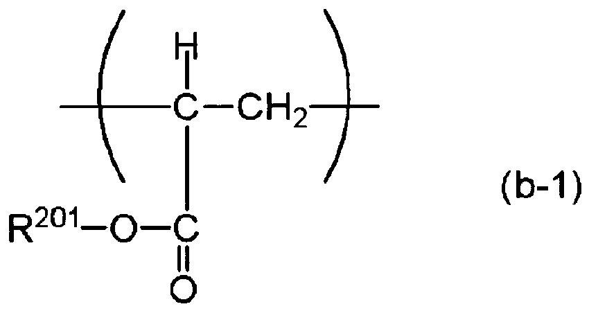
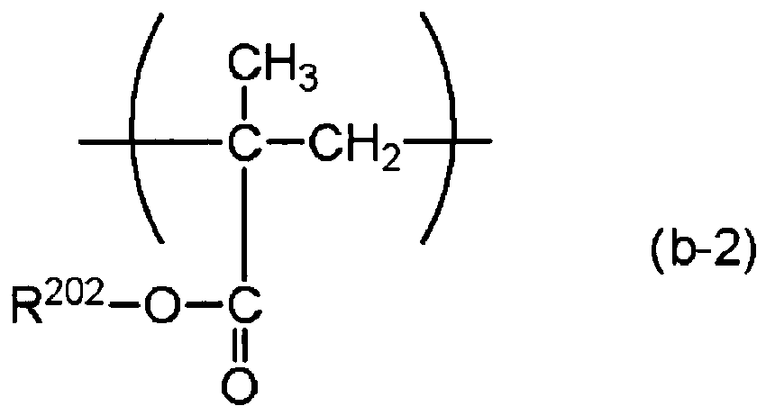
- Elément photosensible électrophotographique suivant la revendication 2 ou 3, dans lequel Y dans la formule (a) est un groupe organique divalent ayant au moins une structure représentée par la formule (c) suivante :

- Elément photosensible électrophotographique suivant l'une quelconque des revendications 1 à 4, dans lequel :le polymère comprenant les motifs structuraux répétés représentés chacun par la formule (1)est synthétisé par polymérisation de composés représentés chacun par la formule (3) suivante :
 70 à 100 % en nombre des composés représentés chacun par la formule (3) étant représentés par au moins une des formules (3-2) à (3-5) suivantes :
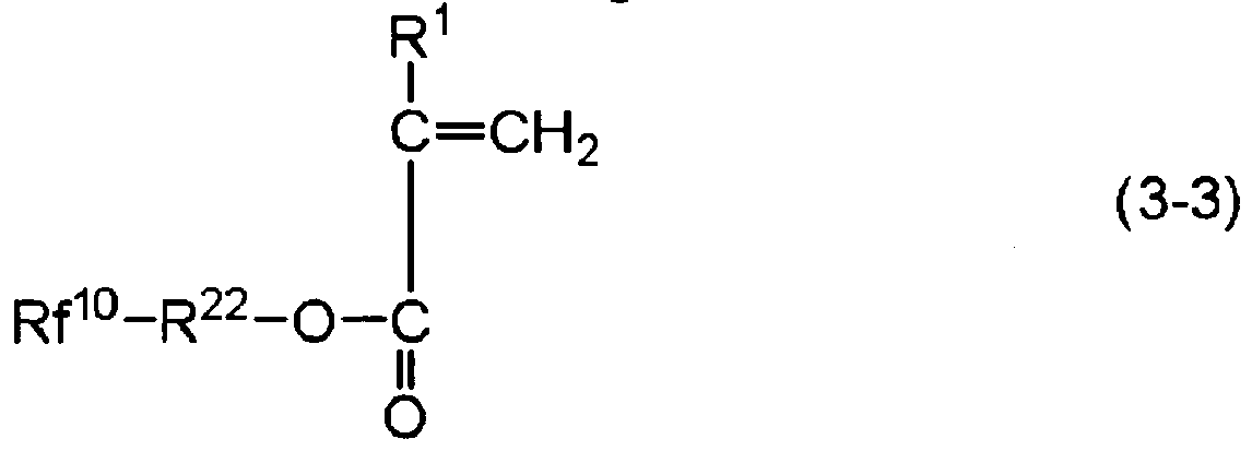

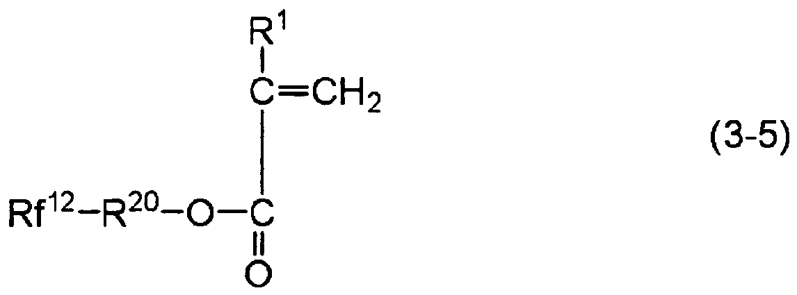
- Elément photosensible électrophotographique suivant l'une quelconque des revendications 2 à 5, :dans lequel le polymère comprenant les motifs structuraux répétés représentés chacun par la formule (1) et les motifs structuraux répétés représentés chacun par la formule (a)est synthétisé par polymérisation de composés représentés chacun par la formule (3) et de composés représentés chacun par la formule (d) suivante :
 70 à 100 % en nombre des composés représentés chacun par la formule (3) étant représentés par au moins une des formules (3-2) à (3-5) suivantes :


- Procédé pour la production de l'élément photosensible électrophotographique suivant l'une quelconque des revendications 1 à 6,
ledit procédé comprenant une étape de formation de la couche de surface de l'élément photosensible électrophotographique en utilisant une solution d'application par revêtement d'une couche de surface contenant le polymère comprenant un motif structural répété représenté par la formule (1). - Cartouche de traitement, comprenant :l'élément photosensible électrophotographique suivant l'une quelconque des revendications 1 à 6 ; etau moins une unité choisie dans le groupe consistant en une unité de charge, une unité de développement et une unité de nettoyage,dans laquelle l'élément et ladite au moins une unité sont portés de manière intégrée et sont fixés de manière amovible à un corps principal d'un appareil électrophotographique.
- Cartouche de traitement suivant la revendication 8, dans laquelle l'unité de nettoyage comprend une lame de nettoyage.
- Appareil électrophotographique, comprenant :l'élément photosensible électrophotographique suivant l'une quelconque des revendications 1 à 6 ;une unité de charge ;une unité d'exposition ;une unité de développement;une unité de transfert ; etune unité de nettoyage.
- Appareil électrophotographique suivant la revendication 10, dans lequel l'unité de nettoyage comprend une lame de nettoyage.
Priority Applications (1)
| Application Number | Priority Date | Filing Date | Title |
|---|---|---|---|
| EP11181407.5A EP2397908B1 (fr) | 2006-10-31 | 2007-10-24 | Corps photosensible électrophotographique, procédé de production d'un corps photosensible électrophotographique, cartouche de traitement et dispositif électrophotographique |
Applications Claiming Priority (7)
| Application Number | Priority Date | Filing Date | Title |
|---|---|---|---|
| JP2006295886 | 2006-10-31 | ||
| JP2006295885 | 2006-10-31 | ||
| JP2006295882 | 2006-10-31 | ||
| JP2006295890 | 2006-10-31 | ||
| JP2006295889 | 2006-10-31 | ||
| JP2007257077 | 2007-10-01 | ||
| PCT/JP2007/071166 WO2008053906A1 (fr) | 2006-10-31 | 2007-10-24 | Corps photosensible électrophotographique, procédé de production d'un corps photosensible électrophotographique, cartouche de traitement et dispositif électrophotographique |
Related Child Applications (2)
| Application Number | Title | Priority Date | Filing Date |
|---|---|---|---|
| EP11181407.5A Division EP2397908B1 (fr) | 2006-10-31 | 2007-10-24 | Corps photosensible électrophotographique, procédé de production d'un corps photosensible électrophotographique, cartouche de traitement et dispositif électrophotographique |
| EP11181407.5 Division-Into | 2011-09-15 |
Publications (3)
| Publication Number | Publication Date |
|---|---|
| EP2071404A1 EP2071404A1 (fr) | 2009-06-17 |
| EP2071404A4 EP2071404A4 (fr) | 2011-07-06 |
| EP2071404B1 true EP2071404B1 (fr) | 2013-02-13 |
Family
ID=39344247
Family Applications (2)
| Application Number | Title | Priority Date | Filing Date |
|---|---|---|---|
| EP07830900A Not-in-force EP2071404B1 (fr) | 2006-10-31 | 2007-10-24 | Corps photosensible électrophotographique, procédé de production d'un corps photosensible électrophotographique, cartouche de traitement et dispositif électrophotographique |
| EP11181407.5A Not-in-force EP2397908B1 (fr) | 2006-10-31 | 2007-10-24 | Corps photosensible électrophotographique, procédé de production d'un corps photosensible électrophotographique, cartouche de traitement et dispositif électrophotographique |
Family Applications After (1)
| Application Number | Title | Priority Date | Filing Date |
|---|---|---|---|
| EP11181407.5A Not-in-force EP2397908B1 (fr) | 2006-10-31 | 2007-10-24 | Corps photosensible électrophotographique, procédé de production d'un corps photosensible électrophotographique, cartouche de traitement et dispositif électrophotographique |
Country Status (6)
| Country | Link |
|---|---|
| US (2) | US7799496B2 (fr) |
| EP (2) | EP2071404B1 (fr) |
| JP (2) | JP4251663B2 (fr) |
| KR (3) | KR20120002557A (fr) |
| CN (2) | CN101535901B (fr) |
| WO (1) | WO2008053906A1 (fr) |
Families Citing this family (31)
| Publication number | Priority date | Publication date | Assignee | Title |
|---|---|---|---|---|
| EP2340465B1 (fr) * | 2008-09-26 | 2015-11-11 | Canon Kabushiki Kaisha | Élément photosensible électrophotographique, cartouche de traitement et appareil électrophotographique |
| JP4663819B1 (ja) | 2009-08-31 | 2011-04-06 | キヤノン株式会社 | 電子写真装置 |
| CN103472674B (zh) | 2009-09-18 | 2017-04-26 | Jsr株式会社 | 放射线敏感性树脂组合物、抗蚀图案形成方法、聚合物和聚合性化合物 |
| JP5740883B2 (ja) * | 2009-09-18 | 2015-07-01 | Jsr株式会社 | アルカリ解離性基を有する重合性の化合物 |
| JP5629588B2 (ja) * | 2010-01-15 | 2014-11-19 | キヤノン株式会社 | 電子写真感光体、プロセスカートリッジおよび電子写真装置 |
| JP5644133B2 (ja) * | 2010-02-23 | 2014-12-24 | 富士ゼロックス株式会社 | 電子写真感光体、プロセスカートリッジ、画像形成装置、電荷輸送性組成物、及び電荷輸送性硬化膜 |
| WO2012035944A1 (fr) | 2010-09-14 | 2012-03-22 | Canon Kabushiki Kaisha | Élément photosensible électrophotographique, cartouche de traitement, appareil électrophotographique et procédé de fabrication d'un élément photosensible électrophotographique |
| JP4948670B2 (ja) | 2010-10-14 | 2012-06-06 | キヤノン株式会社 | 電子写真感光体、プロセスカートリッジ、電子写真装置および電子写真感光体の製造方法 |
| JP4959022B2 (ja) | 2010-10-29 | 2012-06-20 | キヤノン株式会社 | 電子写真感光体、プロセスカートリッジおよび電子写真装置 |
| JP5036901B1 (ja) | 2010-10-29 | 2012-09-26 | キヤノン株式会社 | 電子写真感光体、プロセスカートリッジ、電子写真装置および電子写真感光体の製造方法 |
| JP4975185B1 (ja) | 2010-11-26 | 2012-07-11 | キヤノン株式会社 | 円筒状電子写真感光体の表面層の表面に凸凹形状を形成する方法、および、表面層の表面に凸凹形状が形成された円筒状電子写真感光体を製造する方法 |
| JP4959024B1 (ja) | 2010-12-02 | 2012-06-20 | キヤノン株式会社 | 電子写真感光体、プロセスカートリッジ、電子写真装置、および電子写真感光体の製造方法 |
| JP5610220B2 (ja) * | 2010-12-17 | 2014-10-22 | 株式会社リコー | 電子写真感光体、並びにそれを用いた画像形成装置及びプロセスカートリッジ |
| US9389525B2 (en) | 2011-03-09 | 2016-07-12 | Fuji Xerox Co., Ltd. | Fluorine-containing resin particle dispersion, method for preparing fluorine-containing resin particle dispersion, coating liquid which contains fluorine-containing resin particles, method for preparing coating film which contains fluorine-containing resin particles, coating film which contains fluorine-containing resin particles, molded body, electrophotographic photoreceptor, method for preparing electrophotographic photoreceptor, image forming apparatus, and process cartridge |
| JP6040018B2 (ja) * | 2011-12-22 | 2016-12-07 | キヤノン株式会社 | 電子写真感光体の製造方法、有機デバイスの製造方法、および電荷輸送層用乳化液 |
| JP6049417B2 (ja) * | 2011-12-22 | 2016-12-21 | キヤノン株式会社 | 電荷輸送層を有する電子写真感光体および有機デバイスの製造方法 |
| JP6588731B2 (ja) | 2015-05-07 | 2019-10-09 | キヤノン株式会社 | 電子写真感光体、プロセスカートリッジおよび電子写真装置 |
| JP6639256B2 (ja) | 2016-02-10 | 2020-02-05 | キヤノン株式会社 | 電子写真装置、およびプロセスカートリッジ |
| US10416581B2 (en) | 2016-08-26 | 2019-09-17 | Canon Kabushiki Kaisha | Electrophotographic photosensitive member, process cartridge, and electrophotographic apparatus |
| JP7019350B2 (ja) | 2017-09-01 | 2022-02-15 | キヤノン株式会社 | 電子写真感光体 |
| JP7019351B2 (ja) | 2017-09-01 | 2022-02-15 | キヤノン株式会社 | 電子写真感光体および電子写真装置 |
| JP7046571B2 (ja) | 2017-11-24 | 2022-04-04 | キヤノン株式会社 | プロセスカートリッジ及び電子写真装置 |
| JP7057104B2 (ja) | 2017-11-24 | 2022-04-19 | キヤノン株式会社 | プロセスカートリッジ及び電子写真画像形成装置 |
| JP7187270B2 (ja) | 2017-11-24 | 2022-12-12 | キヤノン株式会社 | プロセスカートリッジ及び電子写真装置 |
| US10747130B2 (en) | 2018-05-31 | 2020-08-18 | Canon Kabushiki Kaisha | Process cartridge and electrophotographic apparatus |
| JP7059111B2 (ja) | 2018-05-31 | 2022-04-25 | キヤノン株式会社 | 電子写真感光体およびその製造方法、並びにプロセスカートリッジおよび電子写真画像形成装置 |
| JP7054366B2 (ja) | 2018-05-31 | 2022-04-13 | キヤノン株式会社 | 電子写真感光体、プロセスカートリッジおよび電子写真装置 |
| US11320754B2 (en) | 2019-07-25 | 2022-05-03 | Canon Kabushiki Kaisha | Process cartridge and electrophotographic apparatus |
| US11573499B2 (en) | 2019-07-25 | 2023-02-07 | Canon Kabushiki Kaisha | Process cartridge and electrophotographic apparatus |
| EP4155824A1 (fr) * | 2021-09-28 | 2023-03-29 | Canon Kabushiki Kaisha | Élément photosensible électrophotographique, cartouche de traitement et appareil électrophotographique, et procédé de production d'élément photosensible électrophotographique |
| JP7817851B2 (ja) * | 2022-02-14 | 2026-02-19 | キヤノン株式会社 | 電子写真感光体、プロセスカートリッジ、電子写真装置、および電子写真感光体の製造方法 |
Family Cites Families (33)
| Publication number | Priority date | Publication date | Assignee | Title |
|---|---|---|---|---|
| JPS5282250A (en) * | 1975-12-27 | 1977-07-09 | Daikin Ind Ltd | Light conductor |
| JPS58164656A (ja) | 1982-03-24 | 1983-09-29 | Toagosei Chem Ind Co Ltd | 改良された被覆組成物 |
| JPS6195358A (ja) * | 1984-10-16 | 1986-05-14 | Minolta Camera Co Ltd | 像形成部材 |
| JPH0650403B2 (ja) * | 1985-05-27 | 1994-06-29 | キヤノン株式会社 | 電子写真感光体 |
| JPH0650404B2 (ja) | 1985-07-12 | 1994-06-29 | キヤノン株式会社 | 像保持部材 |
| JPS6255663A (ja) * | 1985-09-05 | 1987-03-11 | Canon Inc | 電子写真感光体 |
| JPS63221355A (ja) * | 1986-03-18 | 1988-09-14 | Canon Inc | 電子写真感光体 |
| GB2190509B (en) * | 1986-03-18 | 1989-11-22 | Canon Kk | Electrophotographic photosensitive member |
| JPS6414292U (fr) | 1987-07-15 | 1989-01-25 | ||
| JP3137351B2 (ja) | 1991-04-10 | 2001-02-19 | 旭硝子株式会社 | フッ素樹脂組成物、および該組成物を成形した成形体 |
| JPH04326356A (ja) | 1991-04-26 | 1992-11-16 | Matsushita Electric Ind Co Ltd | 積層型電子写真感光体 |
| JPH0675386A (ja) | 1991-07-16 | 1994-03-18 | Matsushita Electric Ind Co Ltd | 電子写真感光体 |
| JPH0527630A (ja) | 1991-07-18 | 1993-02-05 | Canon Inc | 加圧ローラ及び定着装置 |
| US5357320A (en) * | 1992-09-04 | 1994-10-18 | Canon Kabushiki Kaisha | Electrophotographic apparatus |
| JP3097940B2 (ja) * | 1993-05-26 | 2000-10-10 | キヤノン株式会社 | 電子写真感光体及びそれを有する電子写真装置 |
| JPH0915874A (ja) * | 1995-06-28 | 1997-01-17 | Sharp Corp | 電子写真感光体 |
| JP2000275889A (ja) * | 1999-03-23 | 2000-10-06 | Canon Inc | 電子写真感光体、該電子写真感光体を有するプロセスカートリッジ及び電子写真装置 |
| JP3572989B2 (ja) | 1999-04-01 | 2004-10-06 | 三菱マテリアル株式会社 | ペルフルオロアルキル基を有する多面体有機ケイ素化合物 |
| JP4655170B2 (ja) | 2000-01-24 | 2011-03-23 | Dic株式会社 | フルオロアルキル置換(メタ)アクリレートの精製方法およびフッ素系界面活性剤 |
| JP2001302571A (ja) | 2000-04-26 | 2001-10-31 | Asahi Glass Co Ltd | フルオロアルコールの製造方法 |
| JP2003012588A (ja) | 2001-07-02 | 2003-01-15 | Asahi Glass Co Ltd | 含フッ素化合物、その製造方法、含フッ素重合体および撥水撥油剤組成物 |
| JP2003241415A (ja) | 2002-02-20 | 2003-08-27 | Canon Inc | トナー、画像形成装置及びプロセスカートリッジ |
| CN1310096C (zh) * | 2002-07-15 | 2007-04-11 | 佳能株式会社 | 电摄影感光体、电摄影装置和成像处理盒 |
| JP2005017764A (ja) * | 2003-06-26 | 2005-01-20 | Fuji Xerox Co Ltd | 導電部材、像担持体クリーニングユニット、プロセスカートリッジ及び画像形成装置 |
| JP2005054020A (ja) | 2003-08-01 | 2005-03-03 | Yunimatekku Kk | 撥水撥油剤 |
| JP4732704B2 (ja) | 2004-04-30 | 2011-07-27 | 株式会社カネカ | イオン性液体およびその製造方法 |
| JP2006295885A (ja) | 2005-03-14 | 2006-10-26 | Seiko Epson Corp | 操作パネル、その製造方法及び電子制御機器 |
| JP2006295890A (ja) | 2005-03-15 | 2006-10-26 | Fuji Photo Film Co Ltd | アルバム作成装置、アルバム作成方法、及びプログラム |
| JP2006295886A (ja) | 2005-03-16 | 2006-10-26 | Ricoh Co Ltd | 画像処理システム、プログラムおよび記録媒体 |
| JP4624933B2 (ja) | 2005-03-16 | 2011-02-02 | 富士フイルム株式会社 | 撮像装置、撮像方法、アルバム作成装置、アルバム作成方法、アルバム作成システム、及びプログラム |
| TW200636674A (en) | 2005-04-13 | 2006-10-16 | Sunplus Technology Co Ltd | Gamma correction system and method thereof |
| JP4537336B2 (ja) | 2006-03-20 | 2010-09-01 | 三菱電機株式会社 | プログラムデバッグ装置、プログラムデバッグ方法およびデバッグプログラム |
| KR101189027B1 (ko) * | 2006-10-31 | 2012-10-08 | 캐논 가부시끼가이샤 | 전자 사진 감광체, 전자 사진 감광체의 제조 방법, 공정 카트리지 및 전자 사진 장치 |
-
2007
- 2007-10-24 EP EP07830900A patent/EP2071404B1/fr not_active Not-in-force
- 2007-10-24 EP EP11181407.5A patent/EP2397908B1/fr not_active Not-in-force
- 2007-10-24 WO PCT/JP2007/071166 patent/WO2008053906A1/fr not_active Ceased
- 2007-10-24 KR KR1020117029897A patent/KR20120002557A/ko not_active Withdrawn
- 2007-10-24 KR KR1020117010260A patent/KR101188474B1/ko not_active Expired - Fee Related
- 2007-10-24 CN CN2007800408678A patent/CN101535901B/zh not_active Expired - Fee Related
- 2007-10-24 JP JP2008535425A patent/JP4251663B2/ja not_active Expired - Fee Related
- 2007-10-24 KR KR1020097011174A patent/KR101137111B1/ko not_active Expired - Fee Related
- 2007-10-24 CN CN2011102260851A patent/CN102253613B/zh not_active Expired - Fee Related
-
2008
- 2008-04-15 US US12/103,175 patent/US7799496B2/en not_active Expired - Fee Related
- 2008-11-28 JP JP2008303739A patent/JP4654288B2/ja not_active Expired - Fee Related
-
2009
- 2009-03-10 US US12/400,921 patent/US7704657B2/en active Active
Also Published As
| Publication number | Publication date |
|---|---|
| EP2397908B1 (fr) | 2016-04-27 |
| EP2397908A1 (fr) | 2011-12-21 |
| CN101535901B (zh) | 2012-11-21 |
| WO2008053906A1 (fr) | 2008-05-08 |
| KR20120002557A (ko) | 2012-01-05 |
| JPWO2008053906A1 (ja) | 2010-02-25 |
| JP2009104146A (ja) | 2009-05-14 |
| US7704657B2 (en) | 2010-04-27 |
| JP4251663B2 (ja) | 2009-04-08 |
| CN102253613B (zh) | 2013-06-12 |
| EP2071404A1 (fr) | 2009-06-17 |
| JP4654288B2 (ja) | 2011-03-16 |
| US20080199794A1 (en) | 2008-08-21 |
| KR101188474B1 (ko) | 2012-10-08 |
| EP2071404A4 (fr) | 2011-07-06 |
| US20090180800A1 (en) | 2009-07-16 |
| CN101535901A (zh) | 2009-09-16 |
| CN102253613A (zh) | 2011-11-23 |
| US7799496B2 (en) | 2010-09-21 |
| KR20090077845A (ko) | 2009-07-15 |
| KR20110056340A (ko) | 2011-05-26 |
| KR101137111B1 (ko) | 2012-04-20 |
Similar Documents
| Publication | Publication Date | Title |
|---|---|---|
| EP2071404B1 (fr) | Corps photosensible électrophotographique, procédé de production d'un corps photosensible électrophotographique, cartouche de traitement et dispositif électrophotographique | |
| EP2071403B1 (fr) | Corps électrophotographique photosensible, son procédé de fabrication, cartouche de traitement et dispositif électrophotographique | |
| KR101447402B1 (ko) | 전자사진 감광체, 프로세스 카트리지 및 전자사진 장치 | |
| US20070042281A1 (en) | Electrophotographic photoreceptor, and image forming apparatus and process cartridge therefor using the electrophotographic photoreceptor | |
| EP1383008B1 (fr) | Elément photosensible électrophotographique, unité de traitement et appareil électrophotographique l'utilisant | |
| JP2006259063A (ja) | 画像形成装置及び画像形成方法 | |
| JP2009180802A (ja) | 電子写真感光体、プロセスカートリッジ及び電子写真装置 |
Legal Events
| Date | Code | Title | Description |
|---|---|---|---|
| PUAI | Public reference made under article 153(3) epc to a published international application that has entered the european phase |
Free format text: ORIGINAL CODE: 0009012 |
|
| 17P | Request for examination filed |
Effective date: 20090319 |
|
| AK | Designated contracting states |
Kind code of ref document: A1 Designated state(s): AT BE BG CH CY CZ DE DK EE ES FI FR GB GR HU IE IS IT LI LT LU LV MC MT NL PL PT RO SE SI SK TR |
|
| AX | Request for extension of the european patent |
Extension state: AL BA HR MK RS |
|
| RBV | Designated contracting states (corrected) |
Designated state(s): AT BE BG CH CY CZ DE DK EE ES FI FR GB GR HU IE IS IT LI LT LU LV MC MT NL PL PT RO SE SI SK TR |
|
| A4 | Supplementary search report drawn up and despatched |
Effective date: 20110608 |
|
| DAX | Request for extension of the european patent (deleted) | ||
| 17Q | First examination report despatched |
Effective date: 20111221 |
|
| GRAP | Despatch of communication of intention to grant a patent |
Free format text: ORIGINAL CODE: EPIDOSNIGR1 |
|
| GRAS | Grant fee paid |
Free format text: ORIGINAL CODE: EPIDOSNIGR3 |
|
| GRAA | (expected) grant |
Free format text: ORIGINAL CODE: 0009210 |
|
| AK | Designated contracting states |
Kind code of ref document: B1 Designated state(s): DE FR GB IT |
|
| RBV | Designated contracting states (corrected) |
Designated state(s): DE FR GB IT |
|
| REG | Reference to a national code |
Ref country code: GB Ref legal event code: FG4D |
|
| REG | Reference to a national code |
Ref country code: DE Ref legal event code: R096 Ref document number: 602007028447 Country of ref document: DE Effective date: 20130411 |
|
| PLBE | No opposition filed within time limit |
Free format text: ORIGINAL CODE: 0009261 |
|
| STAA | Information on the status of an ep patent application or granted ep patent |
Free format text: STATUS: NO OPPOSITION FILED WITHIN TIME LIMIT |
|
| 26N | No opposition filed |
Effective date: 20131114 |
|
| REG | Reference to a national code |
Ref country code: DE Ref legal event code: R097 Ref document number: 602007028447 Country of ref document: DE Effective date: 20131114 |
|
| REG | Reference to a national code |
Ref country code: FR Ref legal event code: PLFP Year of fee payment: 9 |
|
| PGFP | Annual fee paid to national office [announced via postgrant information from national office to epo] |
Ref country code: GB Payment date: 20151026 Year of fee payment: 9 Ref country code: IT Payment date: 20151005 Year of fee payment: 9 |
|
| PGFP | Annual fee paid to national office [announced via postgrant information from national office to epo] |
Ref country code: FR Payment date: 20151028 Year of fee payment: 9 |
|
| GBPC | Gb: european patent ceased through non-payment of renewal fee |
Effective date: 20161024 |
|
| REG | Reference to a national code |
Ref country code: FR Ref legal event code: ST Effective date: 20170630 |
|
| PG25 | Lapsed in a contracting state [announced via postgrant information from national office to epo] |
Ref country code: GB Free format text: LAPSE BECAUSE OF NON-PAYMENT OF DUE FEES Effective date: 20161024 Ref country code: FR Free format text: LAPSE BECAUSE OF NON-PAYMENT OF DUE FEES Effective date: 20161102 |
|
| PG25 | Lapsed in a contracting state [announced via postgrant information from national office to epo] |
Ref country code: IT Free format text: LAPSE BECAUSE OF NON-PAYMENT OF DUE FEES Effective date: 20161024 |
|
| PGFP | Annual fee paid to national office [announced via postgrant information from national office to epo] |
Ref country code: DE Payment date: 20230920 Year of fee payment: 17 |
|
| REG | Reference to a national code |
Ref country code: DE Ref legal event code: R119 Ref document number: 602007028447 Country of ref document: DE |
|
| PG25 | Lapsed in a contracting state [announced via postgrant information from national office to epo] |
Ref country code: DE Free format text: LAPSE BECAUSE OF NON-PAYMENT OF DUE FEES Effective date: 20250501 |