EP2077192A1 - Luftreifen - Google Patents
Luftreifen Download PDFInfo
- Publication number
- EP2077192A1 EP2077192A1 EP07806737A EP07806737A EP2077192A1 EP 2077192 A1 EP2077192 A1 EP 2077192A1 EP 07806737 A EP07806737 A EP 07806737A EP 07806737 A EP07806737 A EP 07806737A EP 2077192 A1 EP2077192 A1 EP 2077192A1
- Authority
- EP
- European Patent Office
- Prior art keywords
- tire
- circumferential main
- reinforcing layer
- tensile strength
- pneumatic tire
- Prior art date
- Legal status (The legal status is an assumption and is not a legal conclusion. Google has not performed a legal analysis and makes no representation as to the accuracy of the status listed.)
- Granted
Links
Images


Classifications
-
- B—PERFORMING OPERATIONS; TRANSPORTING
- B60—VEHICLES IN GENERAL
- B60C—VEHICLE TYRES; TYRE INFLATION; TYRE CHANGING; CONNECTING VALVES TO INFLATABLE ELASTIC BODIES IN GENERAL; DEVICES OR ARRANGEMENTS RELATED TO TYRES
- B60C9/00—Reinforcements or ply arrangement of pneumatic tyres
- B60C9/18—Structure or arrangement of belts or breakers, crown-reinforcing or cushioning layers
- B60C9/20—Structure or arrangement of belts or breakers, crown-reinforcing or cushioning layers built-up from rubberised plies each having all cords arranged substantially parallel
- B60C9/22—Structure or arrangement of belts or breakers, crown-reinforcing or cushioning layers built-up from rubberised plies each having all cords arranged substantially parallel the plies being arranged with all cords disposed along the circumference of the tyre
-
- B—PERFORMING OPERATIONS; TRANSPORTING
- B60—VEHICLES IN GENERAL
- B60C—VEHICLE TYRES; TYRE INFLATION; TYRE CHANGING; CONNECTING VALVES TO INFLATABLE ELASTIC BODIES IN GENERAL; DEVICES OR ARRANGEMENTS RELATED TO TYRES
- B60C11/00—Tyre tread bands; Tread patterns; Anti-skid inserts
- B60C11/0083—Tyre tread bands; Tread patterns; Anti-skid inserts characterised by the curvature of the tyre tread
-
- B—PERFORMING OPERATIONS; TRANSPORTING
- B60—VEHICLES IN GENERAL
- B60C—VEHICLE TYRES; TYRE INFLATION; TYRE CHANGING; CONNECTING VALVES TO INFLATABLE ELASTIC BODIES IN GENERAL; DEVICES OR ARRANGEMENTS RELATED TO TYRES
- B60C11/00—Tyre tread bands; Tread patterns; Anti-skid inserts
- B60C11/03—Tread patterns
- B60C11/0306—Patterns comprising block rows or discontinuous ribs
-
- B—PERFORMING OPERATIONS; TRANSPORTING
- B60—VEHICLES IN GENERAL
- B60C—VEHICLE TYRES; TYRE INFLATION; TYRE CHANGING; CONNECTING VALVES TO INFLATABLE ELASTIC BODIES IN GENERAL; DEVICES OR ARRANGEMENTS RELATED TO TYRES
- B60C9/00—Reinforcements or ply arrangement of pneumatic tyres
- B60C9/18—Structure or arrangement of belts or breakers, crown-reinforcing or cushioning layers
- B60C9/20—Structure or arrangement of belts or breakers, crown-reinforcing or cushioning layers built-up from rubberised plies each having all cords arranged substantially parallel
- B60C9/22—Structure or arrangement of belts or breakers, crown-reinforcing or cushioning layers built-up from rubberised plies each having all cords arranged substantially parallel the plies being arranged with all cords disposed along the circumference of the tyre
- B60C2009/2252—Physical properties or dimension of the zero degree ply cords
- B60C2009/2266—Density of the cords in width direction
- B60C2009/2271—Density of the cords in width direction with variable density
Definitions
- the present invention relates to a pneumatic tire and more particularly to a pneumatic tire with improved ice handling performance.
- tires such as winter tires for RV (Recreational Vehicle) are required to ensure during traveling in a certain traveling speed range (40 [km/h] or more) as well as traveling at a low speed.
- Patent document 1 a technology disclosed in Patent document 1 has been known as related to a conventional pneumatic tire.
- the conventional pneumatic tire includes symmetric profiles with respect to an equatorial plane.
- the profile on each side of the equatorial plane has at least three tread radii and a tread surface.
- At least two circumferential main grooves are formed on the tread surface.
- Part of the profile between the equatorial plane and the innermost circumferential main groove, part between adjacent circumferential main grooves, and part between the outermost circumferential main groove and a tread contact edge of a shoulder portion form arcs, respectively.
- On the profile are formed inflection points each on an intersection of adjacent arcs in the circumferential main groove. Every acute-angle side intersection angle between adjacent arcs at an inflection point is not less than 1 degree and not more than 3 degrees.
- This structure ensures a contact area of even a wide tire and achieves uniform contact pressure, which improves tire ice handling performance.
- Patent document 1 Japanese Patent Application Laid-open No. 2005-119481
- a pneumatic tire includes a carcass layer that extends across a pair of bead cores, a belt layer that is arranged on a circumference of the carcass layer in a tire-radial direction, a belt reinforcing layer that is arranged on outer side of the belt layer in the tire-radial direction, a plurality of circumferential main grooves that extend in a tire circumferential direction, and a plurality of land portions sectioned by the circumferential main grooves.
- the circumferential main grooves and the land portions are arranged in a tread portion. At least the two circumferential main grooves and at least the three land portions are formed in the tread portion on each side of an equatorial plane.
- profile lines of the land portions form arcs
- an intersection of extension lines of profile lines of adjacent land portions forms an inflection point in an circumferential main groove
- a tensile strength of the belt reinforcing layer in areas of the land portions is larger than a tensile strength of the belt reinforcing layer in an area of the circumferential main groove having the inflection point.
- profile lines of land portions are formed in arc, which widens a contact surface shape of the tire, resulting in an increase in contact area of the tire. Extension lines of the profile lines of adjacent land portions intersect while forming an inflection point in a circumferential main groove, and thereby uniform tire contact pressure is achieved.
- tire ice handling performance improves, particularly during low-speed traveling.
- a tensile strength of a belt reinforcing layer is larger in a land portion area than in a circumferential main groove area having the inflection point.
- the belt reinforcing layer maintains the profile lines having the inflection point appropriate.
- the contact surface shape of the tire is maintained during high-speed traveling (40 [km/h] or more) as well as low-speed traveling. This further improves tire ice handling performance.
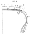
- Fig. 1 is a cross section in tire meridian direction of a pneumatic tire according to an embodiment of the present invention.
- Fig. 2 is an enlarged cross section of a belt reinforcing layer of the pneumatic tire shown in Fig. 1 .
- Figs. 3 to 5 are explanatory diagrams of modified examples of the pneumatic tire shown in Fig. 1 .
- Fig. 6 is a table of results of performance tests of examples of pneumatic tires according to the embodiment of the present invention.
- a pneumatic tire 1 includes a bead core 2, a bead filler 3, a carcass layer 4, a belt layer 5, a tread rubber 6, and a sidewall rubber 7 (see Fig. 1 ).
- the bead core 2 includes a pair of left and right bead cores each having a ring-shaped structure.
- the bead filler 3 is arranged on a tire-radial direction circumference of the bead core 2, and reinforces a bead portion of the pneumatic tire 1.
- the carcass layer 4 is stretched across the left and right bead cores 2 in a toroidal shape to form a framework of the tire.
- the belt layer 5 includes a plurality of belt members 51 and 52 in layers and is arranged on a tire-radial direction circumference of the carcass layer 4.
- the belt layer 5 has a cross-ply structure (in which fiber directions of a layer of the belt members 51 and 52 intersect with each other).
- the tread rubber 6 is arranged on a tire-radial direction circumference of the carcass layer 4 and the belt layer 5 to form the tread portion of the pneumatic tire 1.
- the sidewall rubber 7 is arranged on a tire-width direction outer side of the carcass layer 4 to form a side wall portion of the pneumatic tire 1.
- the pneumatic tire 1 further includes, on a tread surface, a plurality of circumferential main grooves 61 and 62 and land portions 63 to 65 sectioned by the circumferential main grooves 61 and 62 (see Fig. 1 ).
- at least two circumferential main grooves 61 and 62 are formed on the tread surface on each side of the equatorial plane of the pneumatic tire 1, and three land portions 63 to 65 are sectioned by the circumferential main grooves 61 and 62.
- the land portions 63 to 65 can be formed of block rows (block pattern) only, ribs (rib pattern) only, or a combination of block rows and ribs (mix pattern).
- the land portions 63 to 65 include a center land portion (center block or center rib) 63, a second land portion (second block or second rib) 64, and a shoulder land portion (shoulder block or a shoulder rib) 65.
- profile lines of the land portions 63 to 65 are formed in arc (see Fig. 2 ).
- the profile lines of the land portions 63 to 65 form arcs having curvature radii TR1, TR2, and TR3 different from one another.
- the profile line of the shoulder land portion 65 which is the outermost land portion in a tire-width direction, between the circumferential main groove 62 and a contact edge of the tread portion form an arc having the curvature radius TR3.
- this structure increases the width of a tire contact surface shape and a contact area. This increases tire grip and tire ice handling performance.
- adjacent land portions intersect with inflection points Pa and Pb in (e.g., at the centers of) the circumferential main grooves 61 and 62 (curvature profile).
- a chain of arcs constitute the profile lines of the tread portion
- the inflection points of the profile lines are positioned in the circumferential main grooves.
- the inflection points of the profile lines cannot be seen on the land portion 63 to 65, and the contact surfaces of the land portions 63 and 65 have smooth curved lines (arc cross section). Because the contact surfaces of the land portions 63 to 65 are smoothly in contact with the ground during tire rotation, which uniformizes the contact pressure of the tread portion.
- the tire grip increases, and thus, the tire ice handling performance increases.
- the pneumatic tire 1 includes a belt reinforcing layer 8 (see Fig. 1 ).
- the belt reinforcing layer 8 is arranged on a tire-circumferential direction outer side of the belt layer 5, and reinforces the belt layer 5.
- the belt reinforcing layer 8 is formed by winding a belt cover member 81 made of, for example, steel fibers or organic fibers around the circumference of the belt layer 5.
- the belt reinforcing layer 8 covers the belt layer 5 in the tire width direction almost entirely.
- the belt reinforcing layer 8 is formed such that a tensile strength of the belt reinforcing layer 8 in areas of the land portions 63 to 65 larger than that in areas of the circumferential main grooves 61 and 62 (low groove area) having the inflection points Pa and Pb (see Fig. 2 ).
- the tensile strength of the belt reinforcing layer 8 in the areas of the circumferential main grooves 61 and 62 having the inflection points Pa and Pb is set lower than that in other areas.
- the end number (winding density, i.e., the number of times of winding) of the belt cover member 81 of the belt reinforcing layer 8 is set small (low) in the areas of the circumferential main grooves 61 and 62 having the inflection points Pa and Pb and set large (high) in the areas of the land portions 63 to 65.
- the belt reinforcing layer 8 can be formed of a single type of the belt cover member 81 in any one of a single type and a plurality of types as long as the tensile strength relation is satisfied.
- the tensile strength of the belt reinforcing layer 8 is defined by a tensile strength per unit width [N/50 mm].
- the areas of the circumferential main grooves 61 and 62 of the belt reinforcing layer 8 are portions of the belt reinforcing layer 8 in areas corresponding to maximum widths a and b of the circumferential main grooves 61 and 62 (groove lower portions positioned on a tire-radial direction inner side of the circumferential main grooves 61 and 62). If the circumferential main grooves 61 and 62 have a point height, the areas of the circumferential main grooves 61 and 62 of the belt reinforcing layer 8 are portions of the belt reinforcing layer 8 in an area corresponding to the maximum widths a and b, which include the point height.
- the circumferential main grooves 61 and 62 have the inflection points Pa and Pb, and therefore, the tensile strength of the belt reinforcing layer 8 in each of the areas of the circumferential main grooves 61 and 62 is set lower than other areas.
- setting of the tensile strength is not limited to this.
- the tensile strength of the belt reinforcing layer 8 in the area of the circumferential main groove is set to a value equal to the tensile strength of the belt reinforcing layer 8 of the area of an adjacent land portion (not shown).
- the profile lines of the land portions 63 and 64 of the pneumatic tire 1 are formed in arcs, the width of the tire contact surface shape increases and the contact area increases. Furthermore, because the extension lines of the profile lines of the adjacent land portions 63 and 64, and 64 and 65 intersect with the inflection points Pa and Pb in the circumferential main grooves 61 and 62, the tire contact pressure is uniformized. Thus, the tire ice handling performance improves, particularly during low-speed traveling.
- the belt reinforcing layer 8 Because the tensile strength of the belt reinforcing layer 8 in the areas of the land portions 63 to 65 is larger than that in the areas of the circumferential main grooves 61 and 62 having the inflection points Pa and Pb, the belt reinforcing layer 8 appropriately maintains the profile lines having the inflection points Pa and Pb.
- the tire contact surface shape is maintained during low-speed traveling as well as high-speed traveling (40 [km/h] or more], which further improves the tire ice handling performance.
- the profile lines are usually defined while importance is attached to the contact surface shape during low-speed traveling.
- the contact pressure fluctuates due to weight difference of the tread portion between the circumferential main grooves and the land portions, which may lower the tire ice handling performance.
- the extension lines of the profile lines of the adjacent land portions 63 and 64, 64 and 65 intersect with intersection angles ⁇ 1 and ⁇ 2 not less than 1 [deg] and not more than 3 [deg] at the inflecting points Pa and Pb (see Fig. 2 ).
- the intersection angles ⁇ 1 and ⁇ 2 on an acute-angle side of the arcs constituting the profile lines of the adjacent land portions 63 and 64, and 64 and 65 at the respective inflection points Pa and Pb are each within a range not less than 1 [deg] and not more than 3 [deg].
- the intersection angles ⁇ 1 and ⁇ 2 are also formed if the curvature radii TR1 and TR2, and TR2 and TR3 of the intersecting arcs (profile lines of the land portions 63 and 64, and 64 and 65) are equal.
- the tire contact pressure is uniformized particularly when the contact surface width of the tread portion is large. This advantageously improves the tire ice handling performance.
- the curvature radius TR2 (TR3) of the profile lines of the land portion 64 (65) positioned on the tire-width direction outer side out of the profile lines of the adjacent land portions 63 and 64 (64 and 65) be not less than the curvature radius TR1 (TR2) of the profile line of the land portion 63 (64) positioned on the tire-width direction inner side, and that the intersection angle ⁇ 2 at the inflection point Pb positioned on the tire-width direction outer side out of the intersection angles ⁇ 1 and ⁇ 2 at the adjacent inflection points Pa and Pb be not less than the intersection angle ⁇ 2 at the inflection point Pb positioned on the tire-width direction inner side (see Fig. 2 ).
- the curvature radii TR1 to TR3 of the profile lines of the land portions 63 to 65 in the example shown in Fig. 2 have a relation of TR1>TR2>TR3 and the intersection angles ⁇ 1 and ⁇ 2 thereof have the relations of ⁇ 1> ⁇ 2.
- the curvature radii TR1 to TR3 of the profile lines and the intersection angles ⁇ 1 and ⁇ 2 are appropriated.
- the tire contact pressure is uniformized particularly in the structure in which the contact surface width of the tread portion is set larger. This advantageously improves the tire ice handling performance.
- the tensile strength of the belt reinforcing layer 8 in the area of the circumferential main groove 61 (62) having the inflection point Pa (Pb) is within a range of 30 [%] to 80 [%] of the tensile strength of the belt reinforcing layer 8 in the areas of the land portions 63 and 64 (64 and 65) adjacent to the circumferential main groove 61 (62) (see Fig. 2 ).
- the tensile strength of the belt reinforcing layer 8 in the widest circumferential main groove 61 (62) having the inflection point Pa (Pb) is 100, the tensile strength of the belt reinforcing layer 8 in the areas of the land portions 63 and 64 (64 and 65) adjacent to the circumferential main groove 61 (62) on both sides.
- the ratio between the tensile strength of the belt reinforcing layer 8 in the areas of the circumferential main grooves 61 and 62 and that in the areas of the land portions 63 to 65 are appropriated.
- the tire ice handling performance improves, particularly at a traveling speed of 40 [km/h] or more.
- the tensile strength of the belt reinforcing layer 8 in the areas of the land portions 63 and 64 (64 and 65) is less than 30 [%], the curvature profile is accelerated, which often leads to non-uniform tire contact pressure.
- the tensile strength of the belt reinforcing layer 8 in the areas of the land portions 63 and 64 (64 and 65) is more than 80 [%]
- the difference in rising amount between the circumferential main groove 61 (62) and the land portions 63 and 64 (64 and 65) is large, which reduces effect of the curvature profile.
- the width of the land portions 63 to 65 be successively arranged in the tire-width direction and the width of the land portions 63 to 65 (in the tire width direction) be uniformized such that the width is within a range of ⁇ 10 [%] of the average width of the land portions 63 to 65. For example, if two block rows of land portions are successively arranged in the tire width direction and the width of one of the block rows is 100, the width of the other block row is within a range of 90 to 110.
- the interval between centers of the adjacent circumferential main grooves 61 and 62 with respect to the tire contact width is set within a range of ⁇ 30 [%] with respect to the tire contact width/(N+1).
- the rigidity (block strength) of the land portions 63 to 65 are uniformized. This achieves the tire ice handling performance as well as the snow performance. If the width of a portion of the land portions is relatively too small, the portion does not have enough block strength, which reduces the tire ice handling performance. If the width of a portion of the land portions is relatively too large, it is difficult to ensure snow performance.
- any one of a tread pattern (block pattern) including block rows of land portions only and a tread pattern (mix pattern) including block rows and ribs can be adopted.
- the width of the circumferential main grooves 61 and 62 be within a range not less than 3 [mm] and not more than 10 [mm], and the depth of the circumferential main grooves 61 and 62 be within a range not less than 8 [mm] and not more than 16 [mm].
- the width and the depth of the circumferential main grooves 61 and 62 are appropriated, the tire snow performance and tire wear resistance are ensured.
- the width of the circumferential main grooves is more than 10 [mm] or depth of the circumferential main grooves is more than 16 [mm]
- the block strength of the land portions in the tire contact surface decreases, which may cause wear in the land portions.
- the tread portion have a multilayer structure including a tread contact surface portion and an under tread portion, that a JIS-A hardness of the under tread portion be within a range not less than 120 [%] and not more than 200 [%] of the JIS-A rigidity of the tread contact portion, and that the under tread portion have a thickness equal to 40 [%] or more of the depth of the circumferential main grooves 61 and 62 (not shown). In other words, it is preferable that a relatively thick under tread portion be employed. It is also preferable that the depth of the circumferential main grooves 61 and 62 be within a range not less than 30 [%] and not more than 80 [%] of the distance between the belt reinforcing layer 8 and the contact surface of the tread portion.
- a bending angle of a bending portion is set larger to uniformize the tire contact pressure.
- a centrifugal force acting on the tread portion during rotation of the tire deforms the under tread portion particularly in the circumferential main grooves, which leads to non-uniform tire contact pressure.
- the above structure employs the under tread portion having a predetermined JIS-A rigidity and a predetermined thickness with respect to the depths of the circumferential main grooves 61 and 62, deformation of the tread portion is suppressed while the tire rotates, which maintains uniformity in the tire contact pressure. Thus, the tire ice handling performance can be maintained.
- the tensile strength of the belt reinforcing layer 8 in the areas of the circumferential main grooves 61 and 62 having the inflection points Pa and Pb be within a range not less than 10000 [N/50 mm] and not more than 40000 [N/50 mm], and that the tensile strength of the belt reinforcing layer 8 in the land portions 63 to 65 be within a range not less than 12500 [N/50 mm] and not more than 133333 [N/50 mm]. Because the tensile strength of the belt reinforcing layer 8 is appropriated in this structure, the profile lines of the tire are maintained appropriately. This advantageously improves the tire ice handling performance.
- the tensile strength of the belt reinforcing layer 8 be larger in the area of the circumferential main grooves 61 and 62 having the inflection points Pa and Pb on the tire-width direction outer side, and that the tensile strength of the belt reinforcing layer 8 be larger in the area of the land portions 63 to 65 on the tire-width direction outer side.
- the tensile strength of the belt reinforcing layer 8 in the area of the circumferential main groove 62 on the tire-width direction inner side is set larger than that in the area of the circumferential main groove 61 on the tire-width direction inner side
- the tensile strength of the belt reinforcing layer 8 is set such that the tensile strength in the area of the shoulder land portion 65 is larger than that in the area of the second land portion 64, and the tensile strength in the area of the second land portion 64 is larger than that in the center land portion.
- a gripping force of a tread portion is small in edge portions of the belt members 51 and 52.
- the banding force of the tread portion is large in center portions of the belt members 51 and 52.
- the deformation amount in the tread portion on the shoulder portion side significantly increases due to centrifugal force.
- the tensile strength of the belt reinforcing layer 8 is set larger in the tire-width direction outer side (shoulder portion side), deformation of the tread portion is suppressed while the tire rotates.
- the profile lines of the tire is maintained particularly at high speed driving (50 [km/h] or more], which maintains the tire ice handling performance.
- the tensile strength of the belt reinforcing layer 8 in each area be adjusted by changing a cord end number (winding density) of the belt cover member 81 (see Fig. 2 ).
- the belt cover member 81 is wound in the areas of the circumferential main grooves 61 and 62 in a density lower than that in the land portions 63 to 65.
- This structure is preferable because the tensile strength of the belt reinforcing layer 8 in each area can be easily adjusted by adjusting the belt cover member 81 in a single type using conventional tire manufacturing equipment.
- the tensile strength of the belt reinforcing layer 8 can be adjusted by winding or not winding the belt cover member 81 (see Fig. 3 ).
- the belt cover member 81 is not arranged in the areas of the circumferential main grooves 61 and 62 and is wound in the areas of the land portions 63 and 65 only. This structure is preferable because the tensile strength of the belt reinforcing layer 8 can be easily adjusted by adjusting the belt cover member 81 in a single type using conventional tire manufacturing equipment.
- the tensile strength of the belt reinforcing layer 8 can be adjusted by changing the diameter of the belt cover member 81 (see Fig. 4 ).
- the belt cover member 81 having a small diameter is arranged in the areas of the circumferential main grooves 61 and 62 and the belt cover member 81 having a larger diameter is arranged in the areas of the land portions 63 to 65.
- This structure is preferable because the reinforcing strength of the belt reinforcing layer 8 in each area can be easily adjusted while the winding density of the belt cover member 81 is maintained approximately uniform using conventional tire manufacturing equipment.
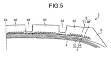
- the tensile strength of the belt reinforcing layer 8 can be adjusted by changing positioning of a strip member constituting the belt cover member 81 that is a jointless belt cover member (see Fig. 5 ). If the belt cover member 81 having a large width is used, for example, the strip member is wound without overlapping in the areas of the circumferential main grooves 61 and 62, and the strip member is wound in an overlapping manner in the areas of the land portions 63 to 65. In this structure, the reinforcing strength of the belt reinforcing layer 8 in each area can be adjusted easily, using conventional tire manufacturing equipment.
- the pneumatic tire 1 be applied to an RV (recreational vehicle) winter tire or a SUV (sports utility vehicle) winter tire.
- RV revisional vehicle
- SUV sport utility vehicle
- Such an winter tire often employs profile lines having inflection points Pa and Pb as those explained above to uniformize widening of the contact surface shape and the contact pressure during low-speed traveling.
- By selecting such winter tires as target tires tire ice handling performance at a predetermined travel speed range (40 [km/h] or more) can be ensured appropriately.
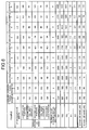
- ice handling performance test was conducted on a plurality of pneumatic tires prepared under different conditions (see Fig. 6 ).
- a pneumatic tire in the 255/55R18 size was mounted on an applicable rim defined by JATMA and an internal pressure of 260 [kPa] and a predetermined load were applied to front tires, and an internal pressure of 290 [kPa] and a predetermined load were applied to rear tires.
- a SUV test vehicle with an engine size of 3500 [cc] mounted with the pneumatic tires was driven on a predetermined icy test course under two conditions of an initial speed of 30 [km/h] and an initial speed of 50 [km/h], and a braking distance when the SUV test vehicle was stopped by an ABS (anti-lock braking system) was measured.
- the braking distance was measured five times and an average of three values except for the minimum and maximum values was calculated. Index was evaluated based on the average using values of Conventional Example 1 as reference (100). A larger value represents a preferable result.
- the tensile strength of belt reinforcing layers of the pneumatic tires of Conventional Examples 1 and 2 were set equal. Curvature radii TR1 to TR3 of profile lines of land portions and intersection angles ⁇ 1 and ⁇ 2 of profile lines of adjacent land portions of Conventional Example 2 were different from those of Conventional Example 1.
- a tensile force of a belt reinforcing layer in the areas of the circumferential main grooves 61 and 62 was different from that in the areas of the land portions 63 to 65 (see Fig. 2 ).
- ice handling performance at an initial speed of 30 [km/h] as well as at an initial speed of 50 [km/h] improves in the pneumatic tires 1 of Examples 1 to 8.
- the tire ice handling performance improves by appropriating the intersection angles ⁇ 1 and ⁇ 2 of the profile lines of adjacent land portions.
- tire ice handling performance improves by appropriating curvature radii TR1 to TR3 of the profile lines of the land portions.
- tire ice handling performance improves by appropriating the tensile strength of the belt reinforcing layer 8 in the areas of the circumferential main grooves 61 and 62.
- tire ice handling performance improves by appropriating the relation between an under tread portion and the depth of the circumferential main grooves 61 and 62.
- tire ice handling performance further improves by appropriating distribution of the tensile strength of the belt reinforcing layer 8 (in the tire width direction).
- the pneumatic tire of the present invention is effective in improving tire ice handling performance.
Landscapes
- Engineering & Computer Science (AREA)
- Mechanical Engineering (AREA)
- Tires In General (AREA)
Applications Claiming Priority (2)
| Application Number | Priority Date | Filing Date | Title |
|---|---|---|---|
| JP2006290204A JP4220542B2 (ja) | 2006-10-25 | 2006-10-25 | 空気入りタイヤ |
| PCT/JP2007/067294 WO2008050545A1 (en) | 2006-10-25 | 2007-09-05 | Pneumatic tire |
Publications (4)
| Publication Number | Publication Date |
|---|---|
| EP2077192A1 true EP2077192A1 (de) | 2009-07-08 |
| EP2077192A4 EP2077192A4 (de) | 2012-04-04 |
| EP2077192B1 EP2077192B1 (de) | 2013-10-23 |
| EP2077192B8 EP2077192B8 (de) | 2014-01-08 |
Family
ID=39324355
Family Applications (1)
| Application Number | Title | Priority Date | Filing Date |
|---|---|---|---|
| EP07806737.8A Ceased EP2077192B8 (de) | 2006-10-25 | 2007-09-05 | Luftreifen |
Country Status (5)
| Country | Link |
|---|---|
| US (1) | US8151841B2 (de) |
| EP (1) | EP2077192B8 (de) |
| JP (1) | JP4220542B2 (de) |
| CN (1) | CN101410259B (de) |
| WO (1) | WO2008050545A1 (de) |
Cited By (4)
| Publication number | Priority date | Publication date | Assignee | Title |
|---|---|---|---|---|
| EP3599112A1 (de) * | 2018-07-24 | 2020-01-29 | Sumitomo Rubber Industries, Ltd. | Reifen ohne spike |
| US11235620B2 (en) * | 2016-03-30 | 2022-02-01 | Bridgestone Corporation | Pneumatic tire |
| US11472230B2 (en) * | 2016-03-30 | 2022-10-18 | Bridgestone Corporation | Pneumatic tire |
| EP4494898A1 (de) * | 2023-07-19 | 2025-01-22 | Sumitomo Rubber Industries, Ltd. | Luftreifen |
Families Citing this family (15)
| Publication number | Priority date | Publication date | Assignee | Title |
|---|---|---|---|---|
| FR2939722B1 (fr) * | 2008-12-17 | 2010-12-31 | Michelin Soc Tech | Pneumatique pour vehicules lourds dont l'armature de sommet comporte au moins une couche d'elements de renforcement circonferentiels |
| JP5316072B2 (ja) * | 2009-02-23 | 2013-10-16 | 横浜ゴム株式会社 | 乗用車用空気入りタイヤ |
| JP2011105100A (ja) * | 2009-11-16 | 2011-06-02 | Bridgestone Corp | 空気入りタイヤ |
| JP5445279B2 (ja) * | 2010-03-31 | 2014-03-19 | 横浜ゴム株式会社 | 空気入りタイヤ |
| JP5543905B2 (ja) * | 2010-12-02 | 2014-07-09 | 東洋ゴム工業株式会社 | 空気入りタイヤ |
| JP5572572B2 (ja) * | 2011-03-03 | 2014-08-13 | 東洋ゴム工業株式会社 | 空気入りタイヤ |
| JP2012196983A (ja) * | 2011-03-18 | 2012-10-18 | Yokohama Rubber Co Ltd:The | 空気入りタイヤ |
| JP6211354B2 (ja) * | 2013-09-04 | 2017-10-11 | 株式会社ブリヂストン | 空気入りタイヤ |
| FR3042737B1 (fr) * | 2015-10-27 | 2017-11-24 | Michelin & Cie | Pneumatique a couches de travail comprenant des monofilaments et a bande de roulement incisee |
| AU2017228601B2 (en) * | 2016-09-25 | 2023-03-23 | The Yokohama Rubber Co., Ltd. | Heavy duty tyre |
| AU2017228598B2 (en) * | 2016-09-25 | 2023-06-15 | The Yokohama Rubber Co., Ltd. | Heavy duty tyre and tread |
| JP2019089409A (ja) * | 2017-11-13 | 2019-06-13 | 株式会社ブリヂストン | タイヤ |
| JP7135752B2 (ja) * | 2018-11-13 | 2022-09-13 | 住友ゴム工業株式会社 | 空気入りタイヤ |
| JP7746821B2 (ja) * | 2021-11-18 | 2025-10-01 | 住友ゴム工業株式会社 | 重荷重用タイヤ |
| JP7220830B1 (ja) | 2022-09-12 | 2023-02-10 | イハラサイエンス株式会社 | ダイヤフラム弁 |
Family Cites Families (26)
| Publication number | Priority date | Publication date | Assignee | Title |
|---|---|---|---|---|
| US118220A (en) * | 1871-08-22 | Improvement in fire-proof floors | ||
| IT1093433B (it) * | 1978-03-09 | 1985-07-19 | Pirelli | Perfezionamento alla struttura anulare di rinforzo per pneumatici radiali |
| JPH01101201A (ja) * | 1987-10-12 | 1989-04-19 | Bridgestone Corp | 空気入りタイヤ |
| JPH0357703A (ja) * | 1989-07-25 | 1991-03-13 | Bridgestone Corp | 偏平空気入りラジアルタイヤ |
| JPH075001B2 (ja) * | 1989-08-24 | 1995-01-25 | 株式会社ブリヂストン | 高性能空気入りラジアルタイヤ |
| US5228933A (en) * | 1989-08-24 | 1993-07-20 | Bridgestone Corporation | High performance pneumatic radial tires |
| JP2702583B2 (ja) * | 1989-11-13 | 1998-01-21 | 株式会社ブリヂストン | 乗用車用空気入りラジアルタイヤ |
| JP2721412B2 (ja) * | 1989-12-28 | 1998-03-04 | 株式会社ブリヂストン | 乗用車用空気入りラジアルタイヤ |
| JPH03123702A (ja) | 1989-10-06 | 1991-05-27 | Tateyama:Kk | 植物の葉脈製造法 |
| JP2906067B2 (ja) * | 1989-11-29 | 1999-06-14 | 横浜ゴム株式会社 | 空気入りスタッドレスタイヤ |
| EP0442678B1 (de) * | 1990-02-15 | 1995-09-06 | Sumitomo Rubber Industries Limited | Luftreifen |
| JPH03123702U (de) * | 1990-03-29 | 1991-12-16 | ||
| JP2954665B2 (ja) * | 1990-06-13 | 1999-09-27 | 株式会社ブリヂストン | 高速走行に適した空気入りラジアルタイヤ |
| JP2769040B2 (ja) * | 1990-11-29 | 1998-06-25 | 株式会社ブリヂストン | 高速走行用空気入りラジアルタイヤ |
| JPH05201204A (ja) * | 1992-01-24 | 1993-08-10 | Yokohama Rubber Co Ltd:The | 空気入りタイヤ |
| JPH05310008A (ja) * | 1992-05-11 | 1993-11-22 | Bridgestone Corp | 空気入りタイヤ |
| JPH05330310A (ja) * | 1992-06-02 | 1993-12-14 | Bridgestone Corp | 空気入りタイヤ |
| JPH06344720A (ja) * | 1993-06-04 | 1994-12-20 | Bridgestone Corp | 空気入りラジアルタイヤ |
| JP2920811B2 (ja) * | 1993-06-25 | 1999-07-19 | 住友ゴム工業株式会社 | スタッドレスタイヤ |
| JP2892914B2 (ja) * | 1993-08-23 | 1999-05-17 | 住友ゴム工業株式会社 | 空気入りタイヤ |
| JP4005212B2 (ja) * | 1998-04-03 | 2007-11-07 | 住友ゴム工業株式会社 | 空気入りタイヤ |
| FR2799411B1 (fr) | 1999-10-11 | 2002-05-24 | Michelin Soc Tech | Pneumatique a endurance amelioree |
| JP2002192914A (ja) * | 2000-12-25 | 2002-07-10 | Yokohama Rubber Co Ltd:The | 氷雪路用空気入りタイヤ |
| JP4327553B2 (ja) * | 2003-10-16 | 2009-09-09 | 横浜ゴム株式会社 | 空気入りタイヤ |
| JP4578842B2 (ja) * | 2004-03-30 | 2010-11-10 | 住友ゴム工業株式会社 | 空気入りタイヤ |
| US20060118220A1 (en) | 2004-12-06 | 2006-06-08 | The Goodyear Tire & Rubber Company | Pneumatic tire with elliptical shoulder |
-
2006
- 2006-10-25 JP JP2006290204A patent/JP4220542B2/ja active Active
-
2007
- 2007-09-05 EP EP07806737.8A patent/EP2077192B8/de not_active Ceased
- 2007-09-05 US US12/162,026 patent/US8151841B2/en not_active Expired - Fee Related
- 2007-09-05 CN CN2007800108777A patent/CN101410259B/zh not_active Expired - Fee Related
- 2007-09-05 WO PCT/JP2007/067294 patent/WO2008050545A1/ja not_active Ceased
Cited By (5)
| Publication number | Priority date | Publication date | Assignee | Title |
|---|---|---|---|---|
| US11235620B2 (en) * | 2016-03-30 | 2022-02-01 | Bridgestone Corporation | Pneumatic tire |
| US11472230B2 (en) * | 2016-03-30 | 2022-10-18 | Bridgestone Corporation | Pneumatic tire |
| EP3599112A1 (de) * | 2018-07-24 | 2020-01-29 | Sumitomo Rubber Industries, Ltd. | Reifen ohne spike |
| CN110774832A (zh) * | 2018-07-24 | 2020-02-11 | 住友橡胶工业株式会社 | 无钉轮胎 |
| EP4494898A1 (de) * | 2023-07-19 | 2025-01-22 | Sumitomo Rubber Industries, Ltd. | Luftreifen |
Also Published As
| Publication number | Publication date |
|---|---|
| CN101410259B (zh) | 2013-08-21 |
| EP2077192A4 (de) | 2012-04-04 |
| JP2008105554A (ja) | 2008-05-08 |
| EP2077192B8 (de) | 2014-01-08 |
| US8151841B2 (en) | 2012-04-10 |
| CN101410259A (zh) | 2009-04-15 |
| US20090205763A1 (en) | 2009-08-20 |
| JP4220542B2 (ja) | 2009-02-04 |
| WO2008050545A1 (en) | 2008-05-02 |
| EP2077192B1 (de) | 2013-10-23 |
Similar Documents
| Publication | Publication Date | Title |
|---|---|---|
| EP2077192B1 (de) | Luftreifen | |
| KR101291886B1 (ko) | 공기 주입 타이어 | |
| EP3284617B1 (de) | Notlaufreifen | |
| RU2527590C2 (ru) | Шина, коронная зона которой имеет придающий жесткость усилитель | |
| EP0602989A1 (de) | Luftreifen | |
| US12344040B2 (en) | Pneumatic tire | |
| US10773554B2 (en) | Pneumatic tire | |
| WO2013042257A1 (ja) | 空気入りタイヤ | |
| WO2014175276A1 (ja) | 空気入りタイヤ | |
| EP0323519B1 (de) | Reifen | |
| JP5541416B1 (ja) | 空気入りタイヤ | |
| EP3882053B1 (de) | Luftreifen | |
| CN105682940A (zh) | 轮胎 | |
| US11524526B2 (en) | Pneumatic tire | |
| EP3882052B1 (de) | Luftreifen | |
| JP3021451B1 (ja) | 重荷重用ラジアルタイヤ | |
| WO2018034060A1 (ja) | 空気入りタイヤ | |
| JP2023150618A (ja) | タイヤ | |
| JPH06191223A (ja) | 空気入りラジアルタイヤ | |
| JP2019026189A (ja) | 空気入りタイヤ | |
| WO2016024390A1 (ja) | 空気入りタイヤ | |
| EP4722002A1 (de) | Luftreifen | |
| JPH10166815A (ja) | 乗用車用空気入りタイヤ | |
| JPH08332808A (ja) | 空気入りタイヤ | |
| JPH07186617A (ja) | 空気入りラジアルタイヤ |
Legal Events
| Date | Code | Title | Description |
|---|---|---|---|
| PUAI | Public reference made under article 153(3) epc to a published international application that has entered the european phase |
Free format text: ORIGINAL CODE: 0009012 |
|
| 17P | Request for examination filed |
Effective date: 20080807 |
|
| AK | Designated contracting states |
Kind code of ref document: A1 Designated state(s): AT BE BG CH CY CZ DE DK EE ES FI FR GB GR HU IE IS IT LI LT LU LV MC MT NL PL PT RO SE SI SK TR |
|
| RBV | Designated contracting states (corrected) |
Designated state(s): AT BE BG CH CY CZ DE DK EE ES FI FR GB GR HU IE IS IT LI LT LU LV MC MT NL PL PT RO SE SI SK TR |
|
| A4 | Supplementary search report drawn up and despatched |
Effective date: 20120307 |
|
| RIC1 | Information provided on ipc code assigned before grant |
Ipc: B60C 9/22 20060101ALI20120301BHEP Ipc: B60C 11/00 20060101AFI20120301BHEP |
|
| DAX | Request for extension of the european patent (deleted) | ||
| RIC1 | Information provided on ipc code assigned before grant |
Ipc: B60C 11/00 20060101AFI20121126BHEP Ipc: B60C 9/22 20060101ALI20121126BHEP |
|
| GRAP | Despatch of communication of intention to grant a patent |
Free format text: ORIGINAL CODE: EPIDOSNIGR1 |
|
| INTG | Intention to grant announced |
Effective date: 20130328 |
|
| GRAS | Grant fee paid |
Free format text: ORIGINAL CODE: EPIDOSNIGR3 |
|
| GRAA | (expected) grant |
Free format text: ORIGINAL CODE: 0009210 |
|
| GRAT | Correction requested after decision to grant or after decision to maintain patent in amended form |
Free format text: ORIGINAL CODE: EPIDOSNCDEC |
|
| AK | Designated contracting states |
Kind code of ref document: B1 Designated state(s): AT BE BG CH CY CZ DE DK EE ES FI FR GB GR HU IE IS IT LI LT LU LV MC MT NL PL PT RO SE SI SK TR |
|
| REG | Reference to a national code |
Ref country code: GB Ref legal event code: FG4D |
|
| REG | Reference to a national code |
Ref country code: CH Ref legal event code: PK Free format text: DIE BENENNUNG CH/LI WURDE VOR DER ERTEILUNG ZURUECKGENOMMEN Ref country code: CH Ref legal event code: EP |
|
| REG | Reference to a national code |
Ref country code: AT Ref legal event code: REF Ref document number: 637339 Country of ref document: AT Kind code of ref document: T Effective date: 20131115 |
|
| RBV | Designated contracting states (corrected) |
Designated state(s): DE |
|
| REG | Reference to a national code |
Ref country code: IE Ref legal event code: FG4D |
|
| REG | Reference to a national code |
Ref country code: NL Ref legal event code: XEP Effective date: 20131018 |
|
| REG | Reference to a national code |
Ref country code: DE Ref legal event code: R096 Ref document number: 602007033489 Country of ref document: DE Effective date: 20131219 |
|
| REG | Reference to a national code |
Ref country code: DE Ref legal event code: R097 Ref document number: 602007033489 Country of ref document: DE |
|
| PLBE | No opposition filed within time limit |
Free format text: ORIGINAL CODE: 0009261 |
|
| STAA | Information on the status of an ep patent application or granted ep patent |
Free format text: STATUS: NO OPPOSITION FILED WITHIN TIME LIMIT |
|
| 26N | No opposition filed |
Effective date: 20140724 |
|
| PGFP | Annual fee paid to national office [announced via postgrant information from national office to epo] |
Ref country code: DE Payment date: 20140903 Year of fee payment: 8 |
|
| REG | Reference to a national code |
Ref country code: DE Ref legal event code: R097 Ref document number: 602007033489 Country of ref document: DE Effective date: 20140724 |
|
| REG | Reference to a national code |
Ref country code: DE Ref legal event code: R119 Ref document number: 602007033489 Country of ref document: DE |
|
| PG25 | Lapsed in a contracting state [announced via postgrant information from national office to epo] |
Ref country code: DE Free format text: LAPSE BECAUSE OF NON-PAYMENT OF DUE FEES Effective date: 20160401 |