EP2077971B1 - Lasttragabschlussanordnung für aufzug - Google Patents
Lasttragabschlussanordnung für aufzug Download PDFInfo
- Publication number
- EP2077971B1 EP2077971B1 EP06813853.6A EP06813853A EP2077971B1 EP 2077971 B1 EP2077971 B1 EP 2077971B1 EP 06813853 A EP06813853 A EP 06813853A EP 2077971 B1 EP2077971 B1 EP 2077971B1
- Authority
- EP
- European Patent Office
- Prior art keywords
- socket
- socket members
- members
- plane
- recited
- Prior art date
- Legal status (The legal status is an assumption and is not a legal conclusion. Google has not performed a legal analysis and makes no representation as to the accuracy of the status listed.)
- Active
Links
Images

Classifications
-
- B—PERFORMING OPERATIONS; TRANSPORTING
- B66—HOISTING; LIFTING; HAULING
- B66B—ELEVATORS; ESCALATORS OR MOVING WALKWAYS
- B66B7/00—Other common features of elevators
- B66B7/06—Arrangements of ropes or cables
- B66B7/08—Arrangements of ropes or cables for connection to the cars or cages, e.g. couplings
- B66B7/085—Belt termination devices
-
- B—PERFORMING OPERATIONS; TRANSPORTING
- B66—HOISTING; LIFTING; HAULING
- B66B—ELEVATORS; ESCALATORS OR MOVING WALKWAYS
- B66B7/00—Other common features of elevators
- B66B7/06—Arrangements of ropes or cables
- B66B7/08—Arrangements of ropes or cables for connection to the cars or cages, e.g. couplings
-
- B—PERFORMING OPERATIONS; TRANSPORTING
- B66—HOISTING; LIFTING; HAULING
- B66B—ELEVATORS; ESCALATORS OR MOVING WALKWAYS
- B66B11/00—Main component parts of lifts in, or associated with, buildings or other structures
- B66B11/02—Cages, i.e. cars
-
- B—PERFORMING OPERATIONS; TRANSPORTING
- B66—HOISTING; LIFTING; HAULING
- B66B—ELEVATORS; ESCALATORS OR MOVING WALKWAYS
- B66B7/00—Other common features of elevators
- B66B7/06—Arrangements of ropes or cables
-
- Y—GENERAL TAGGING OF NEW TECHNOLOGICAL DEVELOPMENTS; GENERAL TAGGING OF CROSS-SECTIONAL TECHNOLOGIES SPANNING OVER SEVERAL SECTIONS OF THE IPC; TECHNICAL SUBJECTS COVERED BY FORMER USPC CROSS-REFERENCE ART COLLECTIONS [XRACs] AND DIGESTS
- Y10—TECHNICAL SUBJECTS COVERED BY FORMER USPC
- Y10T—TECHNICAL SUBJECTS COVERED BY FORMER US CLASSIFICATION
- Y10T24/00—Buckles, buttons, clasps, etc.
- Y10T24/39—Cord and rope holders
- Y10T24/3969—Sliding part or wedge
-
- Y—GENERAL TAGGING OF NEW TECHNOLOGICAL DEVELOPMENTS; GENERAL TAGGING OF CROSS-SECTIONAL TECHNOLOGIES SPANNING OVER SEVERAL SECTIONS OF THE IPC; TECHNICAL SUBJECTS COVERED BY FORMER USPC CROSS-REFERENCE ART COLLECTIONS [XRACs] AND DIGESTS
- Y10—TECHNICAL SUBJECTS COVERED BY FORMER USPC
- Y10T—TECHNICAL SUBJECTS COVERED BY FORMER US CLASSIFICATION
- Y10T29/00—Metal working
- Y10T29/49—Method of mechanical manufacture
- Y10T29/49826—Assembling or joining
Definitions
- This invention generally relates to static connector systems. More particularly, this invention relates to a device for securing an end of a load bearing arrangement.
- Elevator systems typically include some form of load bearing member, such as roping or a belt for supporting and moving the cab through the hoistway as desired.
- the belt couples a counterweight to the cab. Regardless of the specific configuration of the elevator system, it typically is necessary to secure ends of the belt to an appropriate structure within the elevator system.
- a variety of configurations of assemblies for securing the ends of a belt in an elevator system have been used.
- One example includes a cast socket and wedge arrangement where a portion of the belt is secured between the socket and the wedge.
- One disadvantage is that the casting process is relatively expensive and the integral nature of the casting arrangement limits access to the belt-engaging surfaces within the socket. This makes it difficult to treat the belt-engaging surfaces, such as by knurling the belt-engaging surfaces, to enhance the gripping characteristics. Additionally, it is difficult to achieve tolerances desirable for uniform load distribution.
- Another example socket is formed from sheet metal and includes two sheet metal parts bent generally into a U-shape. The U-shaped parts are then joined with a dovetail joint and welded along the joint to form the socket. Shoe parts with knurled belt-engaging surfaces are inserted in the sheet metal parts.
- One drawback of this arrangement is a limited load carrying capacity. It is often difficult to bend sheet metal into the desired configuration if the sheet metal is over 1 ⁇ 4 inch thick. Therefore, it is typically unfeasible to use thicker sheet metal to increase the load carrying capacity of the socket and larger and more cumbersome shoe parts are required.
- WO 01153185 and WO 01151400 describe elevator load bearing termination assemblies.
- a socket as claimed in claim 1 and a method of making a socket as claimed in claim 7.
- Figure 6 shows a modified example of locking the keeper parts and side plates together with a bolt, not forming part of the present invention.
- Figure 7 schematically shows an example positioning member used to precisely assemble a socket device.
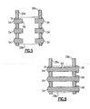
- FIGS 1 through 3 illustrate a device 10 for handling an end of a load bearing member 22 in an elevator system.
- the load bearing member 22 in the illustrated example is a flat belt, however, any load bearing member within an elevator system that can be accommodated using a socket and wedge arrangement designed according to this invention may be used.
- the term "belt" as used in this description should not be construed in its strictest sense. It should be considered synonymous with roping or load bearing member.
- a socket 24 includes side plates 26a and 26b (i.e., first socket members) and keeper parts 28a and 28b (i.e., second socket members) between the side plates 26a and 26b.
- the keeper parts 28a and 28b and the side plates 26a and 26b are distinct, separate pieces that are rigidly secured together and cooperate with a wedge 30 to secure the end of the load bearing member 22 in a desired position.
- the example device 10 has advantages in simplifying the manufacture and assembly of the socket 24 and allowing scaling of the design to a variety of load requirements. Additionally, the example device 10 facilitates flatness, parallelism, and dimensional control, which eliminates the need for insert shoe parts.
- the device 10 includes relatively few parts, including the side plates 26a and 26b, the keeper parts 28a and 28b, the wedge 30, and a connector portion 32 that are assembled together to form the socket 24.
- the side plates 26a and 26b each include recesses 34 such as slots for assembling the socket 24.
- the recesses 34 comprise openings through each side plate 26.
- Each of the keeper parts 28a and 28b includes tabs 38 with beveled end portions that are received at least partially into a corresponding recess 34.
- the tabs 38 include a generally rectangular cross-sectional profile. Given this description, one of ordinary skill in the art will recognize suitable profiles other than rectangular to meet their particular needs.
- the side plates 26a and 26b also each include a connector opening 36 for receiving the connector portion 32.
- the connector portion 32 includes a bridge member 44 having an internally threaded opening 33 that receives a rod 35 that secures the device 10 to a support in a known manner.
- a pin P ( Figure 2 ) is used to secure the rod 35 and bridge member 44 together.
- the recesses 34, connector openings 36, tabs 38, and shape of the side plates 26a and 26b and keeper parts 28a and 28b are laser cut from a metal block. Given this description, one of ordinary skill in the art will recognize alternative processes and materials for making the socket 24.
- the side plates 26a and 26b are spaced a uniform distance apart (i.e., are parallel), and the keeper parts 28a and 28b are transverse to each other and generally perpendicular to the side plates 26a and 26b.
- parallel and perpendicular refer to the nominal relative positioning between the parts and are not intended to be restrictive in a strict geometrical sense.
- some of the recesses 34 are aligned along a first plane P 1 and other recesses 34 are aligned along a second plane P 2 with a desired oblique angle a such as 15° between them.
- the angle ⁇ corresponds to the position of the keeper parts 28a and 28b relative to one another.
- Figure 4 illustrates a view along the section line shown in Figure 1 and shows a locking connection between the tabs 38 of the keeper part 28b and the recesses 34 of the side plates 26a and 26b.
- the locking connection for the keeper part 28a is similar.
- the locking connection provides the benefit of maintaining the keeper parts 28a and 28b at the desired angle while uniformly distributing shear loads from the keeper parts 28a and 28b to the side plates 26a and 26b.
- using a plurality of tabs also provides multiple locations for load distribution.
- the beveled end portions of the tabs 38 form channels 40 with the recesses 34.
- the channels 40 receive a filler material 42 (e.g., braze, solder, or weld filler material) to secure the keeper parts 28a and 28b together with the side plates 26a and 26b.
- a filler material 42 e.g., braze, solder, or weld filler material
- the illustrated example shows the beveled end portions of the tabs 38 being flush with the side plates 26a and 26b, in some examples the tabs 38 extend completely through the recesses 34 or only partially into the recesses 34.
- the connector portion 32 includes a bridge member 44 having beveled ends 46 that are received into the respective connector openings 36. This provides a locking connection similar the locking connection between the tabs 38 and the recesses 34.
- the bridge member 44 transfers load from the side plates 28a and 28b to the rod 35. Given this description, one of ordinary skill in the art will recognize suitable bridge member 44 shapes and configurations other than what is shown to meet their particular needs.
- one or more the surfaces of the wedge 30 and keeper parts 28a and 28b are treated to enhance the gripping characteristics of the socket 24.
- contact surfaces 50 of the keeper parts 28a and 28b and wedge 30 are milled, knurled, or grooved in a known manner to increase friction with the load bearing member 22.
- the separate, distinct keeper parts 28a and 28b provide the benefit of being easily accessible for treatment before assembly with the side plates 26a and 26b.
- the designed size of the side plates 26a and 26b and keeper parts 28a and 28b can be scaled up or down to accommodate a variety of desired load bearing capacities. Since the side plates 26a and 26b and keeper parts 28a and 28b are formed or cut from metal blocks instead of bent sheet metal as in some prior designs, there are fewer manufacturing limitations. that inhibit scale up compared to previously known arrangements. Additionally, this facilitates flatness, parallelism, and dimensional control.
- the angle ⁇ and a wedge angle ⁇ are unequal.
- the wedge angle ⁇ is greater than the angle a.
- the wedge angle ⁇ is 1 ⁇ 2° greater than the angle ⁇ .
- Figure 5 illustrates a modified example not forming part of the present invention.
- a fastener 54 extends through each of the recesses 34 of the side plates 26a and 26b with corresponding openings 56 in the keeper parts 28a and 28b to secure the device 10 together.
- the fastener 54 and openings 56 are threaded to facilitate assembly.
- Figure 6 illustrates another modified example not forming part of the present invention, wherein the fasteners 54 are bolts that extend entirely through the keeper parts 28a and 28b and extend from each side of the side plates 26a and 26b. The bolts are secured in place using a nut 58, Given this description, one of ordinary skill will recognize other ways of securing the parts together to meet their particular needs.
- a positioning member 52 as shown in Figure 7 is used to precisely align the side plates 26a and 26b and keeper parts 28a and 28b.
- the positioning member 52 is approximately the same combined size and shape as a corresponding wedge 30 (shown in phantom) and load bearing member 22 that will be used with that particular socket 24.
- the thickness T of the load bearing member 22 is included on the dimensions of the positioning member 52 in this example.
- the tabs 38 of the keeper parts 28a and 28b are fist into the recesses 34 of the side plates 26a and 26b. In one example, there is some play between the tabs 38 and openings 36.
- the positioning member 52 is then inserted into the socket 24 between the keeper parts 28a and 28b and side plates 26a and 26b.
- a positioning member in the shape of the bridge member 44 is also used for aligning the tops of the side plates 26a and 26b.
- the keeper parts 28a and 28b, side plates 26a and 26b, and positioning member 52 are then clamped together and the distinct pieces are welded, brazed, or soldered (for example) to secure the parts together before removing the positioning member 52.
- the positioning member 52 maintains a precise alignment between the side plates 26a and 26b and keeper parts 28a and 28b during the welding, brazing, or soldering process. This feature provides the benefit of establishing a precise socket 24 assembly, which is desired for maintaining a wedge in a desired position and achieving uniform load distribution on a load bearing member.
Landscapes
- Engineering & Computer Science (AREA)
- Civil Engineering (AREA)
- Mechanical Engineering (AREA)
- Structural Engineering (AREA)
- Lift-Guide Devices, And Elevator Ropes And Cables (AREA)
- Cage And Drive Apparatuses For Elevators (AREA)
- Connection Of Plates (AREA)
Claims (10)
- Aufnahme (24) zum Befestigen eines Endes eines länglichen Lasttrageelements (22), aufweisend:zwei erste Aufnahmeelemente (26a, 26b), die jeweils ein separates und einzelnes Teil aufweisen, das zumindest teilweise eine Aufnahme bildet; undzwei zweite Aufnahmeelemente (28a, 28b), die jeweils ein separates und einzelnes Teil aufweisen, wobei die zweiten Aufnahmeelemente (28a, 28b) voneinander beabstandet sind, um ein Lasttrageelement (22) zwischen den zweiten Aufnahmeelementen (28a, 28b) aufzunehmen, und wobei jedes der beiden ersten Aufnahmeelemente (26a, 26b) an jedem der beiden zweiten Aufnahmeelemente (28a, 28b) starr befestigt ist;wobei die ersten Aufnahmeelemente (26a, 26b) zueinander parallel sind, die zweiten Aufnahmeelemente (28a, 28b) zueinander nicht parallel sind und die beiden zweiten Aufnahmeelemente (28a, 28b) zu den beiden ersten Aufnahmeelementen (26a, 26b) rechtwinklig sind; undwobei die beiden ersten Aufnahmeelemente (26a, 26b) jeweils eine Verriegelungseinrichtung (34) aufweisen und die beiden zweiten Aufnahmeelemente (28a, 28b) jeweils eine entsprechende Verriegelungseinrichtung (38) aufweisen, um die beiden zweiten Aufnahmeelemente (28a, 28b) an den beiden ersten Aufnahmeelementen (26a, 26b) zu befestigen, wobei die Verriegelungseinrichtung (34) mindestens eine Aussparung aufweist, die sich zumindest teilweise in jedes der beiden ersten Aufnahmeelemente (26a, 26b) hinein erstreckt, und wobei die entsprechende Verriegelungseinrichtung (38) mindestens einen Fortsatz aufweist, der sich von jedem der zweiten Aufnahmeelemente (28a, 28b) weg erstreckt und zumindest teilweise in den Aussparungen (34) aufgenommen ist.
- Aufnahme (24) nach Anspruch 1,
wobei die Aussparungen (34) von mindestens einem der beiden ersten Aufnahmeelemente (26a, 26b) erste Öffnungen aufweisen, die entlang einer ersten Ebene (P1) angeordnet sind, sowie zweite Öffnungen aufweisen, die entlang einer zweiten Ebene (P2) angeordnet sind, die quer zu der ersten Ebene (P1) ist, wobei die erste Ebene (P1) und die zweite Ebene (P2) optional einen Winkel von ca. 15° bilden. - Aufnahme (24) nach Anspruch 2,
mit einem Keil (30) zum Einsetzen zwischen den zweiten Aufnahmeelementen (28a, 28b), wobei der Keil (30) einen zugeordneten Keilwinkel aufweist, der von einem Winkel zwischen der ersten Ebene (P1) und der zweiten Ebene (P2) verschieden ist, wobei z.B. der Keilwinkel größer ist als der Winkel zwischen der ersten Ebene (P1) und der zweiten Ebene (P2), wobei z.B. der Keilwinkel 1/2° größer ist als der Winkel zwischen der ersten Ebene (P1) und der zweiten Ebene (P2). - Aufnahme (24) nach Anspruch 1, 2 oder 3,
wobei die Aussparungen (34) jeweils eine Öffnung mit einer peripheren Fläche aufweisen und wobei die Fortsätze (38) abgeschrägte Enden aufweisen, die mit den peripheren Flächen Kanäle (40) bilden, und wahlweise eine Schweißverbindung (42) an den Kanälen (40) aufweisen. - Aufnahme (24) nach einem der Ansprüche 1 bis 4,
wobei mindestens einer der Fortsätze (38) einen rechteckigen Vorsprung aufweist. - Aufnahme (24) nach einem der Ansprüche 1 bis 5,
wobei die beiden ersten Aufnahmeelemente (26a, 26b) eine Verbinderöffnung (36) aufweisen, der zumindest einen Teil eines Verbinderelements (32) aufnimmt, um die Aufnahme (24) mit einem Träger zu verbinden, und wobei optional die Verbinderöffnung (36) eine periphere Fläche aufweist und das Verbinderelement (32) ein abgeschrägtes Ende (46) aufweist, das mit der peripheren Fläche einen Kanal bildet. - Verfahren zum Herstellen einer Aufnahme (24) zur Verwendung in einem Aufzugsystem, wobei zwei erste Aufnahmeelemente (26a, 26b), die die Aufnahme (24) zumindest teilweise bilden, und zwei zweite Aufnahmeelemente (28a, 28b) verwendet werden, wobei es sich bei allen der ersten Aufnahmeelemente (26a, 26b) und der zweiten Aufnahmeelemente (28a, 28b) um separate, einzelne Teile handelt, wobei das Verfahren folgende Schritte aufweist:starres Befestigen von jedem der beiden zweiten Aufnahmeelemente (28a, 28b) an jedem von den beiden ersten Aufnahmeelementen (26a, 26b), um zumindest teilweise eine Aufnahme (24) zwischen den beiden zweiten Aufnahmeelementen (28a, 28b) zu bilden, wobei die ersten Aufnahmeelemente (26a, 26b) zueinander parallel sind, die zweiten Aufnahmeelemente (28a, 28b) zueinander nicht parallel sind und die beiden zweiten Aufnahmeelemente (28a, 28b) zu den beiden ersten Aufnahmeelementen (26a, 26b) rechtwinklig sind; undEinsetzen einer Mehrzahl von Fortsätzen (38), die sich von den beiden zweiten Aufnahmeelementen (28a, 28b) weg erstrecken, in eine entsprechende Mehrzahl von Aussparungen (34) in den beiden ersten Aufnahmeelementen (26a, 26b), um die beiden ersten Aufnahmeelemente (26a, 26b) und die beiden zweiten Aufnahmeelemente (28a, 28b) starr miteinander zu verbinden.
- Verfahren nach Anspruch 7,
das das Verschweißen der Mehrzahl der Fortsätze (38) und der entsprechenden Mehrzahl von Aussparungen (34) beinhaltet. - Verfahren nach Anspruch 7 oder 8,
das das Einsetzen und optionale Einklemmen eines Positionierelements zwischen den zweiten Aufnahmeelementen (28a, 28b) beinhaltet, um eine Beabstandung zwischen den zweiten Aufnahmeelementen (28a, 28b) zu schaffen, die gleich einer kombinierten Größe eines Keils (30) und eines Lasttrageelements (22) ist. - Verfahren nach einem der Ansprüche 7, 8 oder 9,
das das starre Befestigen der beiden zweiten Aufnahmeelemente (28a, 28b) in einem Winkel relativ zueinander sowie rechtwinklig zu den beiden ersten Aufnahmeelementen (26a, 26b) beinhaltet.
Applications Claiming Priority (1)
| Application Number | Priority Date | Filing Date | Title |
|---|---|---|---|
| PCT/US2006/033569 WO2008027030A1 (en) | 2006-08-29 | 2006-08-29 | Elevator load bearing termination assembly |
Publications (2)
| Publication Number | Publication Date |
|---|---|
| EP2077971A1 EP2077971A1 (de) | 2009-07-15 |
| EP2077971B1 true EP2077971B1 (de) | 2014-01-08 |
Family
ID=37963748
Family Applications (1)
| Application Number | Title | Priority Date | Filing Date |
|---|---|---|---|
| EP06813853.6A Active EP2077971B1 (de) | 2006-08-29 | 2006-08-29 | Lasttragabschlussanordnung für aufzug |
Country Status (8)
| Country | Link |
|---|---|
| US (1) | US8505173B2 (de) |
| EP (1) | EP2077971B1 (de) |
| JP (1) | JP5600435B2 (de) |
| KR (1) | KR101147052B1 (de) |
| CN (1) | CN101506082B (de) |
| BR (1) | BRPI0621992A2 (de) |
| ES (1) | ES2445181T3 (de) |
| WO (1) | WO2008027030A1 (de) |
Families Citing this family (25)
| Publication number | Priority date | Publication date | Assignee | Title |
|---|---|---|---|---|
| EP2332874A1 (de) * | 2009-12-10 | 2011-06-15 | Inventio AG | Schlingschloss mit Fixierungselement |
| CN102791606A (zh) * | 2010-03-19 | 2012-11-21 | 三菱电机株式会社 | 电梯的楔式绳头组合装置 |
| EP2878563B1 (de) * | 2013-11-29 | 2017-03-22 | KONE Corporation | Seilendgerätanordnung und Aufzug |
| EP3040301B1 (de) * | 2014-12-30 | 2017-07-05 | KONE Corporation | Seilabschlussanordnung und Hebevorrichtung |
| EP3048076B1 (de) * | 2015-01-21 | 2017-04-19 | KONE Corporation | Seilhebewerkzeug und Seilhebeeinrichtung |
| CN105692391A (zh) * | 2016-03-11 | 2016-06-22 | 南通昌荣机电有限公司 | 一种电梯钢带楔套悬吊装置 |
| US10131521B2 (en) * | 2016-10-24 | 2018-11-20 | Thyssenkrupp Elevator Ag | Belt end termination with a cone clamp |
| KR102485706B1 (ko) * | 2016-11-07 | 2023-01-06 | 오티스 엘리베이터 컴파니 | 엘리베이터 시스템 서스펜션 부재 종단 |
| EP3330210B1 (de) * | 2016-12-02 | 2019-08-07 | Otis Elevator Company | Aufzugssystem-aufhängungselementabschluss mit verbesserter druckverteilung |
| US10183841B2 (en) * | 2016-12-12 | 2019-01-22 | Thyssenkrup Elevator Ag | Multi-wedge end termination for an elevator system |
| CN108217384B (zh) | 2016-12-14 | 2021-07-06 | 奥的斯电梯公司 | 具有约束的电梯系统悬挂构件端接 |
| US11111105B2 (en) | 2017-01-26 | 2021-09-07 | Otis Elevator Company | Compliant shear layer for elevator termination |
| CN106882687A (zh) * | 2017-03-22 | 2017-06-23 | 南通昌荣机电有限公司 | 一种用于电梯钢带的锥套组件 |
| CN106986252A (zh) * | 2017-03-22 | 2017-07-28 | 南通昌荣机电有限公司 | 一种电梯钢带的端接装置 |
| US10562740B2 (en) * | 2017-09-15 | 2020-02-18 | Otis Elevator Company | Elevator load bearing termination assembly for carbon fiber belt |
| US10870557B2 (en) | 2017-10-12 | 2020-12-22 | Otis Elevator Company | Compact belt termination assembly |
| CN108910655B (zh) * | 2018-08-30 | 2023-10-27 | 苏州江南嘉捷电梯有限公司 | 一种易拆卸锥套组件 |
| CN112638812A (zh) * | 2018-09-04 | 2021-04-09 | 蒂森克虏伯电梯创新与运营有限公司 | 电梯受拉构件端部封端 |
| EP3725725B1 (de) * | 2019-04-17 | 2022-02-09 | KONE Corporation | Seilgreifelement einer hebevorrichtung, seilgreifvorrichtung, endgeräteanordnung und hebevorrichtung |
| KR102190289B1 (ko) * | 2019-05-23 | 2020-12-11 | 현대엘리베이터주식회사 | 벨트 종단 장치 |
| FI129671B (fi) * | 2019-09-09 | 2022-06-30 | Konecranes Global Oy | Nostimen köysikiinnitysjärjestely |
| ES1237550Y (es) * | 2019-10-03 | 2020-02-11 | Talleres Agui S A | Amarre de elemento tensor |
| CN113062375B (zh) * | 2021-03-12 | 2022-04-29 | 中联重科股份有限公司 | 机械臂及挖掘机 |
| US12038066B2 (en) * | 2022-01-31 | 2024-07-16 | Gates Corporation | Clamp for flat belts |
| DE102023129480A1 (de) | 2023-10-25 | 2024-08-01 | Tk Elevator Innovation And Operations Gmbh | Riemenbefestigungseinheit und damit ausgestattete Aufzugsanlage sowie Verwendung |
Family Cites Families (42)
| Publication number | Priority date | Publication date | Assignee | Title |
|---|---|---|---|---|
| US2130040A (en) * | 1935-12-31 | 1938-09-13 | Macwhyte Company | Wire line sling and fitting therefor |
| US2482231A (en) * | 1944-07-13 | 1949-09-20 | Joseph T White | Cable lock |
| US2540887A (en) * | 1948-12-31 | 1951-02-06 | Auld D L Co | Cable-anchoring and -tightening device |
| US2977654A (en) * | 1957-12-02 | 1961-04-04 | Page Engineering Company | Rope wedge socket |
| US3335470A (en) * | 1965-11-23 | 1967-08-15 | Bucyrus Eric Company | Collapsible wedge for cable connection |
| BE795073A (fr) * | 1972-03-02 | 1973-05-29 | Gen Electric | Procede pour la fabrication d'aubes creuses |
| US3811155A (en) * | 1972-06-21 | 1974-05-21 | L Stafford | Rope grab assembly |
| US3905711A (en) * | 1974-10-31 | 1975-09-16 | Marion Power Shovel Co | Cable connecting assembly |
| DE2511953A1 (de) | 1975-03-19 | 1976-09-30 | Anton Schoener | Stufenlose zugschnurarretierung, insbesondere fuer schwingfluegel |
| US4295749A (en) * | 1979-08-15 | 1981-10-20 | Mcbride Jack L | Eye splice fitting |
| DE3143217C2 (de) | 1981-10-30 | 1983-11-03 | Geroh GmbH Mechanische Systeme, 8551 Waischenfeld | "Seilklemme mit Klemmbacke und Klemmkeil" |
| US4561154A (en) * | 1984-04-26 | 1985-12-31 | Esco Corporation | Wedge-type rope socket connection and method |
| USRE32847E (en) * | 1984-04-26 | 1989-01-31 | Esco Corporation | Wedge-type rope socket connection and method |
| US4572565A (en) * | 1984-08-09 | 1986-02-25 | Washington Chain & Supply Company, Inc. | Stopper for a wire rope |
| US4602891A (en) * | 1985-05-10 | 1986-07-29 | Mcbride Arlen P | Open wedge socket |
| US4643609A (en) * | 1986-01-17 | 1987-02-17 | Cibeles International Inc. | Gripping assembly for elongated objects such as cables or bars |
| SU1318758A1 (ru) | 1986-02-18 | 1987-06-23 | Б. В. Алексеев | Зажим дл каната |
| US4716991A (en) * | 1986-07-21 | 1988-01-05 | Carl Riechers | Elevator guide shoe |
| US4718788A (en) * | 1986-08-05 | 1988-01-12 | Esco Corporation | Wire rope equalizer socket |
| JPH0724492Y2 (ja) * | 1987-05-21 | 1995-06-05 | 株式会社ピー・エス | Frp製ロ−プの緊張定着体 |
| JPH01242385A (ja) | 1988-03-23 | 1989-09-27 | Mitsubishi Electric Corp | エレベータ用ロープ引止め装置 |
| SU1736982A1 (ru) | 1989-05-06 | 1992-05-30 | Институт Химии Поверхности Ан Усср | Способ получени сорбента |
| US5199137A (en) * | 1991-03-25 | 1993-04-06 | Nylube Products, Co. | Rope guard assembly for wedge clamp |
| JPH05172190A (ja) | 1991-12-26 | 1993-07-09 | Hitachi Constr Mach Co Ltd | ロープ連結具 |
| US5553360A (en) * | 1995-05-19 | 1996-09-10 | The Crosby Group, Inc. | Extended wedge socket assembly |
| US5988929A (en) * | 1996-10-09 | 1999-11-23 | Columbia Steel Casting Co. | Easy-out cable socket wedge and method for use thereof |
| EP0941394A4 (de) * | 1996-11-27 | 2007-01-17 | Diebold Sst Holding Company In | Herstellungsverfahren für eine sichere einfassung für einen geldautomaten |
| FR2789609B1 (fr) * | 1999-02-16 | 2001-04-27 | Armor Inox Sa | Procede d'assemblage de toles et structure rigide obtenue par ledit procede |
| AU709308B3 (en) | 1999-05-28 | 1999-08-26 | Cunnington, Maria Elisabeth | Rope hitch |
| US6058575A (en) * | 1999-06-07 | 2000-05-09 | Dagan; Gideon | Cable clamp |
| JP2001165245A (ja) | 1999-12-08 | 2001-06-19 | Mitsubishi Electric Corp | 楔式ロープ留め装置 |
| US6484368B1 (en) * | 2000-01-11 | 2002-11-26 | Otis Elevator Company | Flexible flat tension member termination device |
| US6345419B1 (en) * | 2000-01-19 | 2002-02-12 | Otis Elevator Company | Termination for flat flexible tension member |
| US20020154945A1 (en) * | 2001-04-18 | 2002-10-24 | Ericson Richard J. | Elevator load bearing termination assembly with constant profile extrusion |
| US6994487B2 (en) * | 2001-04-18 | 2006-02-07 | Otis Elevator Company | Elevator load bearing termination assembly |
| US6662408B2 (en) * | 2001-09-07 | 2003-12-16 | Otis Elevator Company | Elevator load bearing termination assembly with gripping inserts |
| FR2846898B1 (fr) * | 2002-11-07 | 2005-07-15 | Snecma Moteurs | Procede de soudage laser en une passe d'un assemblage en t de pieces metalliques |
| US20050132873A1 (en) * | 2003-12-23 | 2005-06-23 | Labock Technologies, Inc. | Method of connecting rigid bodies and rigid body |
| DE502005000294D1 (de) * | 2004-04-23 | 2007-02-22 | Sulzer Chemtech Ag | Fluideintrittseinrichtung für einen Apparat, insbesondere für eine Kolonne |
| EP1642855B1 (de) * | 2004-09-13 | 2008-12-17 | Inventio Ag | Tragmittelendverbindung zur Befestigung eines Endes eines Tragmittels in einer Aufzugsanlage und Verfahren zur Befestigung eines Endes eines Tragmittels in einer Aufzugsanlage |
| JP5172190B2 (ja) | 2007-03-28 | 2013-03-27 | 株式会社ニデック | 眼鏡レンズ加工装置 |
| JP5039180B2 (ja) | 2010-06-29 | 2012-10-03 | 株式会社ツヅキ | 建築物の外断熱工法における支持ボルトの補強工法及び補強金具 |
-
2006
- 2006-08-29 CN CN200680055717.XA patent/CN101506082B/zh active Active
- 2006-08-29 BR BRPI0621992-6A patent/BRPI0621992A2/pt not_active IP Right Cessation
- 2006-08-29 WO PCT/US2006/033569 patent/WO2008027030A1/en not_active Ceased
- 2006-08-29 JP JP2009526576A patent/JP5600435B2/ja active Active
- 2006-08-29 EP EP06813853.6A patent/EP2077971B1/de active Active
- 2006-08-29 KR KR1020097006421A patent/KR101147052B1/ko not_active Expired - Fee Related
- 2006-08-29 ES ES06813853.6T patent/ES2445181T3/es active Active
- 2006-08-29 US US12/376,198 patent/US8505173B2/en active Active
Also Published As
| Publication number | Publication date |
|---|---|
| EP2077971A1 (de) | 2009-07-15 |
| KR101147052B1 (ko) | 2012-05-17 |
| US20090307876A1 (en) | 2009-12-17 |
| CN101506082B (zh) | 2016-04-27 |
| ES2445181T3 (es) | 2014-02-28 |
| US8505173B2 (en) | 2013-08-13 |
| BRPI0621992A2 (pt) | 2011-12-27 |
| JP2010502532A (ja) | 2010-01-28 |
| JP5600435B2 (ja) | 2014-10-01 |
| KR20090047550A (ko) | 2009-05-12 |
| WO2008027030A1 (en) | 2008-03-06 |
| CN101506082A (zh) | 2009-08-12 |
Similar Documents
| Publication | Publication Date | Title |
|---|---|---|
| EP2077971B1 (de) | Lasttragabschlussanordnung für aufzug | |
| CN110875449B (zh) | 电池组以及电池组的制造方法 | |
| CN1313348C (zh) | 带有夹持插入件的电梯承载终端组件 | |
| JP6906548B2 (ja) | スプリングクリップ、取り付け具、接触相手を固定する方法、及び接触相手との間で電気的接続と機械的接続を確立する接続システム | |
| US20210226244A1 (en) | Fuel cell module | |
| JP2023037010A (ja) | パルス溶接コイル及びその寿命を延長させる方法 | |
| US7909530B2 (en) | Connection hardware for wooden building | |
| CA2676943C (en) | Electrical connector | |
| EP3998844A1 (de) | Kanalmesserrücken | |
| US20060214073A1 (en) | Fabricated heavy duty structural clamp | |
| CN101298125B (zh) | 用于制造多个涡轮部件的方法和装置 | |
| HK1137716A (en) | Elevator load bearing termination assembly | |
| US20150292540A1 (en) | Wedge clamping system for beams | |
| EP3832808B1 (de) | Modulares befestigungssystem und verfahren dafür | |
| JP7083284B2 (ja) | 中間クランプ | |
| JP5341387B2 (ja) | コンクリート型枠用根止め金具 | |
| EP3771780B1 (de) | An einer decke oder einer wand befestigbare trägerstruktur | |
| EP4039631B1 (de) | Spannelementanker | |
| JP7654439B2 (ja) | 引張試験用試験片つかみ治具および引張試験方法 | |
| JP2024055672A (ja) | 組合せ梁及び組合せ梁の固定構造 | |
| JP2009102879A (ja) | 棒状鉄骨部材の接合構造及び接合方法 | |
| JP2005304233A (ja) | バスダクトの支持構造 | |
| HK1077282B (en) | Elevator load bearing termination assembly with gripping inserts | |
| JPH06299543A (ja) | コンクリート矢板の頂部連結方法 |
Legal Events
| Date | Code | Title | Description |
|---|---|---|---|
| PUAI | Public reference made under article 153(3) epc to a published international application that has entered the european phase |
Free format text: ORIGINAL CODE: 0009012 |
|
| 17P | Request for examination filed |
Effective date: 20090330 |
|
| AK | Designated contracting states |
Kind code of ref document: A1 Designated state(s): AT BE BG CH CY CZ DE DK EE ES FI FR GB GR HU IE IS IT LI LT LU LV MC NL PL PT RO SE SI SK TR |
|
| AX | Request for extension of the european patent |
Extension state: AL BA HR MK RS |
|
| 17Q | First examination report despatched |
Effective date: 20120120 |
|
| DAX | Request for extension of the european patent (deleted) | ||
| GRAP | Despatch of communication of intention to grant a patent |
Free format text: ORIGINAL CODE: EPIDOSNIGR1 |
|
| INTG | Intention to grant announced |
Effective date: 20130719 |
|
| GRAS | Grant fee paid |
Free format text: ORIGINAL CODE: EPIDOSNIGR3 |
|
| GRAA | (expected) grant |
Free format text: ORIGINAL CODE: 0009210 |
|
| AK | Designated contracting states |
Kind code of ref document: B1 Designated state(s): AT BE BG CH CY CZ DE DK EE ES FI FR GB GR HU IE IS IT LI LT LU LV MC NL PL PT RO SE SI SK TR |
|
| REG | Reference to a national code |
Ref country code: GB Ref legal event code: FG4D |
|
| REG | Reference to a national code |
Ref country code: CH Ref legal event code: EP |
|
| REG | Reference to a national code |
Ref country code: IE Ref legal event code: FG4D |
|
| REG | Reference to a national code |
Ref country code: AT Ref legal event code: REF Ref document number: 648602 Country of ref document: AT Kind code of ref document: T Effective date: 20140215 |
|
| REG | Reference to a national code |
Ref country code: DE Ref legal event code: R096 Ref document number: 602006039997 Country of ref document: DE Effective date: 20140220 |
|
| REG | Reference to a national code |
Ref country code: ES Ref legal event code: FG2A Ref document number: 2445181 Country of ref document: ES Kind code of ref document: T3 Effective date: 20140228 |
|
| REG | Reference to a national code |
Ref country code: AT Ref legal event code: MK05 Ref document number: 648602 Country of ref document: AT Kind code of ref document: T Effective date: 20140108 |
|
| REG | Reference to a national code |
Ref country code: NL Ref legal event code: VDEP Effective date: 20140108 |
|
| REG | Reference to a national code |
Ref country code: LT Ref legal event code: MG4D |
|
| PG25 | Lapsed in a contracting state [announced via postgrant information from national office to epo] |
Ref country code: IS Free format text: LAPSE BECAUSE OF FAILURE TO SUBMIT A TRANSLATION OF THE DESCRIPTION OR TO PAY THE FEE WITHIN THE PRESCRIBED TIME-LIMIT Effective date: 20140508 Ref country code: LT Free format text: LAPSE BECAUSE OF FAILURE TO SUBMIT A TRANSLATION OF THE DESCRIPTION OR TO PAY THE FEE WITHIN THE PRESCRIBED TIME-LIMIT Effective date: 20140108 |
|
| PG25 | Lapsed in a contracting state [announced via postgrant information from national office to epo] |
Ref country code: NL Free format text: LAPSE BECAUSE OF FAILURE TO SUBMIT A TRANSLATION OF THE DESCRIPTION OR TO PAY THE FEE WITHIN THE PRESCRIBED TIME-LIMIT Effective date: 20140108 Ref country code: SE Free format text: LAPSE BECAUSE OF FAILURE TO SUBMIT A TRANSLATION OF THE DESCRIPTION OR TO PAY THE FEE WITHIN THE PRESCRIBED TIME-LIMIT Effective date: 20140108 Ref country code: CY Free format text: LAPSE BECAUSE OF FAILURE TO SUBMIT A TRANSLATION OF THE DESCRIPTION OR TO PAY THE FEE WITHIN THE PRESCRIBED TIME-LIMIT Effective date: 20140108 Ref country code: FI Free format text: LAPSE BECAUSE OF FAILURE TO SUBMIT A TRANSLATION OF THE DESCRIPTION OR TO PAY THE FEE WITHIN THE PRESCRIBED TIME-LIMIT Effective date: 20140108 Ref country code: PT Free format text: LAPSE BECAUSE OF FAILURE TO SUBMIT A TRANSLATION OF THE DESCRIPTION OR TO PAY THE FEE WITHIN THE PRESCRIBED TIME-LIMIT Effective date: 20140508 Ref country code: AT Free format text: LAPSE BECAUSE OF FAILURE TO SUBMIT A TRANSLATION OF THE DESCRIPTION OR TO PAY THE FEE WITHIN THE PRESCRIBED TIME-LIMIT Effective date: 20140108 |
|
| PG25 | Lapsed in a contracting state [announced via postgrant information from national office to epo] |
Ref country code: LV Free format text: LAPSE BECAUSE OF FAILURE TO SUBMIT A TRANSLATION OF THE DESCRIPTION OR TO PAY THE FEE WITHIN THE PRESCRIBED TIME-LIMIT Effective date: 20140108 Ref country code: BE Free format text: LAPSE BECAUSE OF FAILURE TO SUBMIT A TRANSLATION OF THE DESCRIPTION OR TO PAY THE FEE WITHIN THE PRESCRIBED TIME-LIMIT Effective date: 20140108 |
|
| REG | Reference to a national code |
Ref country code: DE Ref legal event code: R097 Ref document number: 602006039997 Country of ref document: DE |
|
| PG25 | Lapsed in a contracting state [announced via postgrant information from national office to epo] |
Ref country code: DK Free format text: LAPSE BECAUSE OF FAILURE TO SUBMIT A TRANSLATION OF THE DESCRIPTION OR TO PAY THE FEE WITHIN THE PRESCRIBED TIME-LIMIT Effective date: 20140108 Ref country code: CZ Free format text: LAPSE BECAUSE OF FAILURE TO SUBMIT A TRANSLATION OF THE DESCRIPTION OR TO PAY THE FEE WITHIN THE PRESCRIBED TIME-LIMIT Effective date: 20140108 Ref country code: RO Free format text: LAPSE BECAUSE OF FAILURE TO SUBMIT A TRANSLATION OF THE DESCRIPTION OR TO PAY THE FEE WITHIN THE PRESCRIBED TIME-LIMIT Effective date: 20140108 Ref country code: EE Free format text: LAPSE BECAUSE OF FAILURE TO SUBMIT A TRANSLATION OF THE DESCRIPTION OR TO PAY THE FEE WITHIN THE PRESCRIBED TIME-LIMIT Effective date: 20140108 |
|
| PLBE | No opposition filed within time limit |
Free format text: ORIGINAL CODE: 0009261 |
|
| STAA | Information on the status of an ep patent application or granted ep patent |
Free format text: STATUS: NO OPPOSITION FILED WITHIN TIME LIMIT |
|
| PG25 | Lapsed in a contracting state [announced via postgrant information from national office to epo] |
Ref country code: SK Free format text: LAPSE BECAUSE OF FAILURE TO SUBMIT A TRANSLATION OF THE DESCRIPTION OR TO PAY THE FEE WITHIN THE PRESCRIBED TIME-LIMIT Effective date: 20140108 Ref country code: PL Free format text: LAPSE BECAUSE OF FAILURE TO SUBMIT A TRANSLATION OF THE DESCRIPTION OR TO PAY THE FEE WITHIN THE PRESCRIBED TIME-LIMIT Effective date: 20140108 |
|
| PGFP | Annual fee paid to national office [announced via postgrant information from national office to epo] |
Ref country code: TR Payment date: 20140721 Year of fee payment: 9 Ref country code: GB Payment date: 20140827 Year of fee payment: 9 |
|
| 26N | No opposition filed |
Effective date: 20141009 |
|
| REG | Reference to a national code |
Ref country code: DE Ref legal event code: R097 Ref document number: 602006039997 Country of ref document: DE Effective date: 20141009 |
|
| PG25 | Lapsed in a contracting state [announced via postgrant information from national office to epo] |
Ref country code: MC Free format text: LAPSE BECAUSE OF FAILURE TO SUBMIT A TRANSLATION OF THE DESCRIPTION OR TO PAY THE FEE WITHIN THE PRESCRIBED TIME-LIMIT Effective date: 20140108 Ref country code: LU Free format text: LAPSE BECAUSE OF FAILURE TO SUBMIT A TRANSLATION OF THE DESCRIPTION OR TO PAY THE FEE WITHIN THE PRESCRIBED TIME-LIMIT Effective date: 20140829 |
|
| REG | Reference to a national code |
Ref country code: CH Ref legal event code: PL |
|
| PG25 | Lapsed in a contracting state [announced via postgrant information from national office to epo] |
Ref country code: LI Free format text: LAPSE BECAUSE OF NON-PAYMENT OF DUE FEES Effective date: 20140831 Ref country code: CH Free format text: LAPSE BECAUSE OF NON-PAYMENT OF DUE FEES Effective date: 20140831 |
|
| REG | Reference to a national code |
Ref country code: IE Ref legal event code: MM4A |
|
| PG25 | Lapsed in a contracting state [announced via postgrant information from national office to epo] |
Ref country code: SI Free format text: LAPSE BECAUSE OF FAILURE TO SUBMIT A TRANSLATION OF THE DESCRIPTION OR TO PAY THE FEE WITHIN THE PRESCRIBED TIME-LIMIT Effective date: 20140108 |
|
| PG25 | Lapsed in a contracting state [announced via postgrant information from national office to epo] |
Ref country code: IE Free format text: LAPSE BECAUSE OF NON-PAYMENT OF DUE FEES Effective date: 20140829 |
|
| PGFP | Annual fee paid to national office [announced via postgrant information from national office to epo] |
Ref country code: IT Payment date: 20150728 Year of fee payment: 10 |
|
| GBPC | Gb: european patent ceased through non-payment of renewal fee |
Effective date: 20150829 |
|
| PG25 | Lapsed in a contracting state [announced via postgrant information from national office to epo] |
Ref country code: BG Free format text: LAPSE BECAUSE OF FAILURE TO SUBMIT A TRANSLATION OF THE DESCRIPTION OR TO PAY THE FEE WITHIN THE PRESCRIBED TIME-LIMIT Effective date: 20140108 |
|
| PG25 | Lapsed in a contracting state [announced via postgrant information from national office to epo] |
Ref country code: GR Free format text: LAPSE BECAUSE OF FAILURE TO SUBMIT A TRANSLATION OF THE DESCRIPTION OR TO PAY THE FEE WITHIN THE PRESCRIBED TIME-LIMIT Effective date: 20140409 |
|
| REG | Reference to a national code |
Ref country code: FR Ref legal event code: PLFP Year of fee payment: 11 |
|
| PG25 | Lapsed in a contracting state [announced via postgrant information from national office to epo] |
Ref country code: GB Free format text: LAPSE BECAUSE OF NON-PAYMENT OF DUE FEES Effective date: 20150829 Ref country code: HU Free format text: LAPSE BECAUSE OF FAILURE TO SUBMIT A TRANSLATION OF THE DESCRIPTION OR TO PAY THE FEE WITHIN THE PRESCRIBED TIME-LIMIT; INVALID AB INITIO Effective date: 20060829 |
|
| REG | Reference to a national code |
Ref country code: DE Ref legal event code: R082 Ref document number: 602006039997 Country of ref document: DE Representative=s name: SCHMITT-NILSON SCHRAUD WAIBEL WOHLFROM PATENTA, DE |
|
| REG | Reference to a national code |
Ref country code: FR Ref legal event code: PLFP Year of fee payment: 12 |
|
| PG25 | Lapsed in a contracting state [announced via postgrant information from national office to epo] |
Ref country code: TR Free format text: LAPSE BECAUSE OF NON-PAYMENT OF DUE FEES Effective date: 20150829 Ref country code: IT Free format text: LAPSE BECAUSE OF NON-PAYMENT OF DUE FEES Effective date: 20160829 |
|
| REG | Reference to a national code |
Ref country code: FR Ref legal event code: PLFP Year of fee payment: 13 |
|
| PGFP | Annual fee paid to national office [announced via postgrant information from national office to epo] |
Ref country code: ES Payment date: 20230901 Year of fee payment: 18 |
|
| PGFP | Annual fee paid to national office [announced via postgrant information from national office to epo] |
Ref country code: FR Payment date: 20230720 Year of fee payment: 18 |
|
| PG25 | Lapsed in a contracting state [announced via postgrant information from national office to epo] |
Ref country code: FR Free format text: LAPSE BECAUSE OF NON-PAYMENT OF DUE FEES Effective date: 20240831 |
|
| REG | Reference to a national code |
Ref country code: ES Ref legal event code: FD2A Effective date: 20251002 |
|
| PG25 | Lapsed in a contracting state [announced via postgrant information from national office to epo] |
Ref country code: ES Free format text: LAPSE BECAUSE OF NON-PAYMENT OF DUE FEES Effective date: 20240830 |
|
| PGFP | Annual fee paid to national office [announced via postgrant information from national office to epo] |
Ref country code: DE Payment date: 20250724 Year of fee payment: 20 |