EP2079911B1 - Tubulure de clapet d'étranglement - Google Patents
Tubulure de clapet d'étranglement Download PDFInfo
- Publication number
- EP2079911B1 EP2079911B1 EP07821073A EP07821073A EP2079911B1 EP 2079911 B1 EP2079911 B1 EP 2079911B1 EP 07821073 A EP07821073 A EP 07821073A EP 07821073 A EP07821073 A EP 07821073A EP 2079911 B1 EP2079911 B1 EP 2079911B1
- Authority
- EP
- European Patent Office
- Prior art keywords
- throttle flap
- throttle
- shaft
- connecting piece
- edge
- Prior art date
- Legal status (The legal status is an assumption and is not a legal conclusion. Google has not performed a legal analysis and makes no representation as to the accuracy of the status listed.)
- Ceased
Links
Images


Classifications
-
- F—MECHANICAL ENGINEERING; LIGHTING; HEATING; WEAPONS; BLASTING
- F02—COMBUSTION ENGINES; HOT-GAS OR COMBUSTION-PRODUCT ENGINE PLANTS
- F02D—CONTROLLING COMBUSTION ENGINES
- F02D9/00—Controlling engines by throttling air or fuel-and-air induction conduits or exhaust conduits
- F02D9/08—Throttle valves specially adapted therefor; Arrangements of such valves in conduits
- F02D9/10—Throttle valves specially adapted therefor; Arrangements of such valves in conduits having pivotally-mounted flaps
-
- F—MECHANICAL ENGINEERING; LIGHTING; HEATING; WEAPONS; BLASTING
- F02—COMBUSTION ENGINES; HOT-GAS OR COMBUSTION-PRODUCT ENGINE PLANTS
- F02D—CONTROLLING COMBUSTION ENGINES
- F02D9/00—Controlling engines by throttling air or fuel-and-air induction conduits or exhaust conduits
- F02D9/08—Throttle valves specially adapted therefor; Arrangements of such valves in conduits
- F02D9/10—Throttle valves specially adapted therefor; Arrangements of such valves in conduits having pivotally-mounted flaps
- F02D9/1005—Details of the flap
- F02D9/101—Special flap shapes, ribs, bores or the like
- F02D9/1015—Details of the edge of the flap, e.g. for lowering flow noise or improving flow sealing in closed flap position
-
- F—MECHANICAL ENGINEERING; LIGHTING; HEATING; WEAPONS; BLASTING
- F02—COMBUSTION ENGINES; HOT-GAS OR COMBUSTION-PRODUCT ENGINE PLANTS
- F02D—CONTROLLING COMBUSTION ENGINES
- F02D9/00—Controlling engines by throttling air or fuel-and-air induction conduits or exhaust conduits
- F02D9/08—Throttle valves specially adapted therefor; Arrangements of such valves in conduits
-
- F—MECHANICAL ENGINEERING; LIGHTING; HEATING; WEAPONS; BLASTING
- F16—ENGINEERING ELEMENTS AND UNITS; GENERAL MEASURES FOR PRODUCING AND MAINTAINING EFFECTIVE FUNCTIONING OF MACHINES OR INSTALLATIONS; THERMAL INSULATION IN GENERAL
- F16K—VALVES; TAPS; COCKS; ACTUATING-FLOATS; DEVICES FOR VENTING OR AERATING
- F16K3/00—Gate valves or sliding valves, i.e. cut-off apparatus with closing members having a sliding movement along the seat for opening and closing
- F16K3/02—Gate valves or sliding valves, i.e. cut-off apparatus with closing members having a sliding movement along the seat for opening and closing with flat sealing faces; Packings therefor
- F16K3/04—Gate valves or sliding valves, i.e. cut-off apparatus with closing members having a sliding movement along the seat for opening and closing with flat sealing faces; Packings therefor with pivoted closure members
Definitions
- the invention relates to a throttle body with a housing in which a through-hole is formed, which is closed by a arranged on a throttle shaft and associated with this throttle valve cross-section, wherein the throttle shaft with its lateral ends in bearing recesses of the housing about an axis of rotation is pivotally mounted, wherein the radially encircling edge of the throttle is annular and has a reduced thickness compared to the thickness of the throttle, wherein the two opposite ring sides of the radially encircling annular edge of the throttle valve extend symmetrically to a rotational axis intersecting radials of the throttle shaft.
- the recess has such a depth beyond the axis of rotation of the throttle valve shaft depth, that the throttle valve extends symmetrically to the axis of rotation radially.
- the radially directed annular surface of the throttle valve is made by turning.
- the throttle valve is mounted on the throttle shaft in such a way that even the region of the throttle flap which is not reduced in thickness extends symmetrically with respect to the radial axis of the throttle flap which intersects the axis of rotation.
- the object of the invention is to provide a throttle body of the type mentioned above, which avoids these disadvantages and has a reduced risk of contamination and ice formation and blocking the throttle at its radially peripheral area.
- This design results in a low production time for the radially encircling annular edge.
- the radial depth of the flattening in the throttle flap shaft can be reduced and therefore only reduced material removal may be required, since it is not necessary to take into account the thickness of the throttle flap in its central attachment region but only in its region of the edge.
- the greater thickness of the throttle flap ensures in its central region a high stability of the throttle valve, while the radially encircling annular edge due to its smaller thickness leads to a lower accumulation of dirt and moisture in this edge region, so that accordingly also the possibility of ice formation and As a result, a blockage of the throttle valve is reduced.
- the circumferential annular edge of the throttle valve has a thickness of the order of about 1 mm.
- the throttle may have a thickness on the order of between approximately 1.5 mm and 3 mm outside the radially encircling annular edge.
- the throttle valve can be produced in that the throttle valve is a stamped component.
- the radially directed circumferential annular surface of the annular edge of reduced thickness is a punching surface, then the percentage of the smooth cut in relation to the portion of the punch cut is very large due to the smaller material thickness in the edge region, whereby the possibility of accumulation of dirt and moisture in this region is largely eliminated ,
- the punching surface is a Repassierstanz Structure (precision punching surface), wherein the Repassierstanzvorgang takes place after the generation of the radially encircling edge, so a smooth cut portion of approximately 100% at the radial directed circumferential annular surface of the annular edge reaches.
- the flattening of the throttle shaft may form a receiving groove having a depth extending beyond the rotational axis of the throttle shaft.
- the region of the throttle flap which is enclosed by the annular edge is preferably flat.
- the object of the invention is achieved in that the flattening is formed tangentially on one side of the axis of rotation of the throttle shaft, wherein the throttle has a central, lying flat on the flat bearing area, to each other opposite to each other to the contour of the throttle shaft cuddly quarter-round Area adjoins, which merges into a plane of rotation approximately radially radial flap area.
- the contact area of the throttle flap is greater than the flattening of the throttle valve shaft transversely to and / or in the longitudinal extent of the throttle valve shaft, a displacement of the preassembled throttle valve on the throttle valve shaft for assembly purposes and a self-centering of the throttle valve in the throttle body is possible.
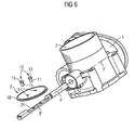
- the throttle valve can be fastened to the throttle shaft by means of one or more radial screws that are radial to the throttle valve shaft, which project through bores in the throttle valve and are screwed into threaded bores in the throttle shaft.
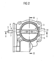
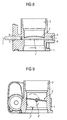
- the illustrated throttle body for an air intake duct of a motor vehicle have a housing 1 with a through-passage opening 2, which can be closed by a throttle valve 3, 3 '.
- the throttle valve 3, 3 ' is arranged on a throttle valve shaft 4, 4', which extends transversely to the passage opening 2 and protrude with their lateral ends 5 in bearing recesses 6 of the housing 1 and are pivotally mounted about a rotation axis 2.
- the throttle shaft 4 has a flattening 8, 8 ', on which the throttle valve 3, 3' in support and with the throttle shaft 3, 3 'is connected.
- the flattening 8 is formed tangentially on one side of the axis of rotation 7 of the throttle shaft 4.
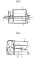
- the throttle valve 3 is a stamped / bent part made of a metal sheet and has a diagonally continuously extending bead 14.
- the bead 14 has a central, planar contact region 15 of slightly greater extent transversely to the throttle shaft 4 than the width of the flattening 8.
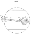
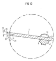
- a radially encircling edge 18 is annularly formed on the throttle valve 3 and has a reduced thickness 20 with respect to the thickness 19 of the sheet metal of the throttle valve 3.
- the annular edge 18 is formed by a one-sided axial stamping on the flattening 8 of the throttle shaft 4 side facing away from the throttle valve 3.
- edge 18 of the radially outer edge of the throttle valve 3 is on the side facing away from the flattening 8 stepped, while the other side of the throttle valve 3 has no such stage.
- the edge 18 extends radially to the axis of rotation. 7
- the flattening 8 ' forms a receiving groove 21 for the throttle valve 4', which has a depth extending beyond the axis of rotation 7.
- FIGS. 1 to 5 also owns the embodiment of FIGS. 6 to 10 a radially encircling rim 18 having a reduced thickness 20 with respect to the thickness 10 of the sheet metal of the throttle valve 3 '.
- the annular edge 18 is formed by a one-sided Axiallessness on the flattening 8 'of the throttle shaft 4 side facing away from the throttle valve 3 stages, wherein the edge 18 extends radially to the axis of rotation 7.
- the flattening 8 'facing side of the throttle valve 3' has no such stage.
- the throttle valve 3, 3 'on the flat 8, 8' slidably adjusts its position of the through hole 2 and can now be screwed in this adjusted position by means of screws 10 on the throttle shaft 4, 4 '.
Landscapes
- Engineering & Computer Science (AREA)
- General Engineering & Computer Science (AREA)
- Mechanical Engineering (AREA)
- Chemical & Material Sciences (AREA)
- Combustion & Propulsion (AREA)
- Lift Valve (AREA)
Abstract
Claims (11)
- Tubulure de papillon des gaz, comprenant un corps (1) dans lequel est formé une ouverture (2) de passage traversante qui peut être fermée par un volet (3, 3') d'étranglement de section transversale circulaire placé sur un arbre (4, 4') de volet d'étranglement et relié à celui-ci, l'arbre (4, 4') du volet d'étranglement étant monté tournant autour d'un axe (7) de rotation par ses extrémités latérales dans des évidements de palier du corps, le bord (18) s'étendant radialement du volet (3, 3') d'étranglement étant de type annulaire et ayant une épaisseur (20) réduite par rapport à l'épaisseur (19) du volet (3, 3') d'étranglement, dans lequel les deux côtés annulaires opposés l'un à l'autre du bord (18) s'étendant radialement du volet (3, 3') d'étranglement s'étendent de manière symétrique par rapport à un rayon coupant l'axe (7) de rotation de l'arbre (4, 4') du volet d'étranglement, le volet (3, 3') d'étranglement étant appliqué sur un méplat (8, 8') formé sur l'arbre (4, 4') du volet d'étranglement et s'étendant dans la direction longitudinale de l'arbre (4, 4') du volet d'étranglement et étant relié à cet arbre (4, 4') du volet d'étranglement, le bord (18) de type annulaire s'étendant radialement du volet (3, 3') d'étranglement étant un estampage axial d'un côté du volet (3, 3') d'étranglement du côté du volet (3, 3') d'étranglement éloigné du méplat de l'arbre du volet d'étranglement, caractérisé en ce que le méplat (8) est formé tangentiellement sur un côté de l'axe (7) de rotation de l'arbre (4) du volet d'étranglement, le volet (3) d'étranglement ayant une zone (15) d'application médiane s'appliquant à plat sur le méplat (8) et à laquelle se raccorde en étant opposée l'une à l'autre respectivement une zone de type à quart de cercle épousant le contour de l'arbre (4) du volet d'étranglement, zone qui se transforme en une zone (17) de volet à peu près radiale par rapport à l'axe (7) de rotation.
- Tubulure de papillon des gaz suivant la revendication 1, caractérisée en ce que le bord (8) de type annulaire faisant le tour du volet (3, 3') d'étranglement a une épaisseur (20) d'environ 1mm.
- Tubulure de papillon des gaz suivant l'une des revendications précédentes, caractérisée en ce que le volet (3, 3') d'étranglement a, à l'extérieur du bord (18) de type annulaire faisant le tour radialement, une épaisseur (19) comprise entre à peu près 1,5 mm et 3 mm.
- Tubulure de papillon des gaz suivant l'une des revendications précédentes, caractérisée en ce que le volet (3, 3') d'étranglement est une pièce découpée.
- Tubulure de papillon des gaz suivant l'une des revendications précédentes, caractérisée en ce que la surface (22) annulaire faisant le tour et dirigée radialement du bord (18) de type annulaire d'épaisseur (20) réduite est une surface découpée.
- Tubulure de papillon des gaz suivant la revendication 5, caractérisée en ce que la surface découpée est une surface découpée repassée (surface découpée de précision).
- Tubulure de papillon des gaz suivant l'une des revendications précédentes, caractérisée en ce que le méplat (8') de l'arbre (4') du volet d'étranglement forme une rainure (21) de réception, qui a une épaisseur allant au-delà de l'axe (7) de rotation de l'arbre (4') du volet d'étranglement.
- Tubulure de papillon des gaz suivant la revendication 7, caractérisée en ce que la zone du volet (3') d'étranglement entourée par le bord (8) de type annulaire est plate.
- Tubulure de papillon des gaz suivant la revendication 8, caractérisée en ce que la zone (15) d'application du volet (5) d'étranglement est plus grande transversalement et/ou dans la direction longitudinale de l'arbre (4) du volet d'étranglement que le méplat (8) de l'arbre (4) du volet d'étranglement.
- Tubulure de papillon des gaz suivant l'une des revendications précédentes, caractérisée en ce que le volet (3, 3') d'étranglement peut être fixé à l'arbre (4, 4') du volet d'étranglement par une ou par plusieurs vis (10) radiales par rapport à l'arbre (4, 4') du volet d'étranglement, vis qui pénètrent dans des trous (9) du volet (3, 3') d'étranglement et sont vissées dans des taraudages (12) de l'arbre (4, 4') du volet d'étranglement.
- Tubulure de papillon des gaz suivant la revendication 10, caractérisée en ce que le diamètre des trous (9) est plus grand que le diamètre des vis (10).
Applications Claiming Priority (2)
| Application Number | Priority Date | Filing Date | Title |
|---|---|---|---|
| DE102006048179A DE102006048179A1 (de) | 2006-10-10 | 2006-10-10 | Drosselklappenstutzen |
| PCT/EP2007/060704 WO2008043754A1 (fr) | 2006-10-10 | 2007-10-09 | Tubulure de clapet d'étranglement |
Publications (2)
| Publication Number | Publication Date |
|---|---|
| EP2079911A1 EP2079911A1 (fr) | 2009-07-22 |
| EP2079911B1 true EP2079911B1 (fr) | 2011-12-14 |
Family
ID=38846617
Family Applications (1)
| Application Number | Title | Priority Date | Filing Date |
|---|---|---|---|
| EP07821073A Ceased EP2079911B1 (fr) | 2006-10-10 | 2007-10-09 | Tubulure de clapet d'étranglement |
Country Status (5)
| Country | Link |
|---|---|
| EP (1) | EP2079911B1 (fr) |
| KR (1) | KR101406405B1 (fr) |
| CN (1) | CN101523032A (fr) |
| DE (1) | DE102006048179A1 (fr) |
| WO (1) | WO2008043754A1 (fr) |
Cited By (1)
| Publication number | Priority date | Publication date | Assignee | Title |
|---|---|---|---|---|
| US12259053B2 (en) | 2021-03-26 | 2025-03-25 | Sankei Giken Kogyo Co., Ltd. | Exhaust valve |
Families Citing this family (6)
| Publication number | Priority date | Publication date | Assignee | Title |
|---|---|---|---|---|
| DE102010023412B4 (de) * | 2010-06-11 | 2012-05-24 | Pierburg Gmbh | Klappenvorrichtung für eine Verbrennungskraftmaschine |
| JP2013104390A (ja) * | 2011-11-15 | 2013-05-30 | Aisan Industry Co Ltd | スロットル装置 |
| DE102013203845B4 (de) * | 2013-03-06 | 2015-02-19 | Continental Automotive Gmbh | Ventilvorrichtung für ein Kraftfahrzeug |
| DE102014226733A1 (de) * | 2014-12-19 | 2016-06-23 | Continental Automotive Gmbh | Ventilvorrichtung in einem Kraftfahrzeug |
| KR101663127B1 (ko) * | 2015-10-15 | 2016-10-07 | 주식회사 그린에어텍 | 소음저감형 댐퍼 |
| JP7469074B2 (ja) * | 2020-03-02 | 2024-04-16 | 三恵技研工業株式会社 | 排気バルブ |
Family Cites Families (12)
| Publication number | Priority date | Publication date | Assignee | Title |
|---|---|---|---|---|
| DE1846108U (de) * | 1960-07-01 | 1962-02-01 | Henschel Werke G M B H | Motorbremse fuer kraftfahrzeuge. |
| JPH0742870B2 (ja) * | 1983-08-26 | 1995-05-15 | 株式会社日立製作所 | 空気制御弁装置 |
| DE3643948A1 (de) * | 1986-12-22 | 1988-06-23 | Vdo Schindling | Drosselklappenstutzen fuer eine brennkraftmaschine |
| US4860706A (en) * | 1987-09-14 | 1989-08-29 | Aisan Kogyo Kabushiki Kaisha | Throttle body |
| US5081972A (en) * | 1990-02-16 | 1992-01-21 | Siemens Automotive L.P. | Engine throttle blade sealing |
| DE19500475C2 (de) * | 1995-01-10 | 2001-09-27 | Schatz Thermo Gastech Gmbh | Absperr- oder Drosselventil mit drehbarer Ventilklappe |
| DE19600567A1 (de) * | 1996-01-09 | 1997-03-27 | Daimler Benz Ag | Vorrichtung zur Drosselung eines eine Leitung passierenden Fluidstromes |
| JPH10103087A (ja) * | 1996-10-01 | 1998-04-21 | Mitsubishi Electric Corp | 制御弁装置 |
| JP3712533B2 (ja) * | 1998-06-30 | 2005-11-02 | 愛三工業株式会社 | 内燃機関の吸気制御バルブ装置 |
| US6129071A (en) * | 1998-07-20 | 2000-10-10 | Ford Global Technologies, Inc. | Throttle valve system |
| DE10050393A1 (de) * | 2000-10-12 | 2002-04-18 | Siemens Ag | Drosselklappenstutzen |
| GB0130086D0 (en) * | 2001-12-17 | 2002-02-06 | Delphi Tech Inc | Flap valve for fluid flow passage |
-
2006
- 2006-10-10 DE DE102006048179A patent/DE102006048179A1/de not_active Withdrawn
-
2007
- 2007-10-09 WO PCT/EP2007/060704 patent/WO2008043754A1/fr not_active Ceased
- 2007-10-09 CN CNA2007800380140A patent/CN101523032A/zh active Pending
- 2007-10-09 EP EP07821073A patent/EP2079911B1/fr not_active Ceased
- 2007-10-09 KR KR1020097009236A patent/KR101406405B1/ko not_active Expired - Fee Related
Cited By (1)
| Publication number | Priority date | Publication date | Assignee | Title |
|---|---|---|---|---|
| US12259053B2 (en) | 2021-03-26 | 2025-03-25 | Sankei Giken Kogyo Co., Ltd. | Exhaust valve |
Also Published As
| Publication number | Publication date |
|---|---|
| EP2079911A1 (fr) | 2009-07-22 |
| KR20090094810A (ko) | 2009-09-08 |
| DE102006048179A1 (de) | 2008-04-17 |
| WO2008043754A1 (fr) | 2008-04-17 |
| CN101523032A (zh) | 2009-09-02 |
| KR101406405B1 (ko) | 2014-06-13 |
Similar Documents
| Publication | Publication Date | Title |
|---|---|---|
| EP2079911B1 (fr) | Tubulure de clapet d'étranglement | |
| DE10141996B4 (de) | Kugelumlaufmutter | |
| EP3025040B1 (fr) | Soupape | |
| DE3307554A1 (de) | Elektrisch regelbares druckreduzierventil | |
| EP0991867A1 (fr) | Soupape hydraulique, notamment pour assurer la commande d'un deplacement d'arbre a cames dans une automobile | |
| EP3099527A1 (fr) | Mécanisme de commande pour véhicule automobile, en particulier pour siège de véhicule automobile | |
| DE102009001309A1 (de) | Taumelgelenkbeschlag für eine Verstellvorrichtung eines Kraftfahrzeugsitzes, insbesondere für einen Rückenlehnengelenkbeschlag | |
| EP1430232B1 (fr) | Frein a disque destine notamment a un vehicule utilitaire | |
| DE102006007363A1 (de) | Vorgesteuertes Druckbegrenzungsventil | |
| DE2442010A1 (de) | Hydraulikkopf fuer eine einspritzpumpe und mit diesem hydraulikkopf ausgeruestete einspritzpumpe | |
| DE102022101114A1 (de) | Ventilvorrichtung | |
| DE102004045730B3 (de) | Klappenvorrichtung für ein Luftansaugkanalsystem einer Verbrennungskraftmaschine | |
| EP1090240A1 (fr) | Soupape a limitation de pression | |
| WO2001020207A1 (fr) | Soupape a encastrer pour un radiateur a elements multiples | |
| DE202016103802U1 (de) | Getriebeeinheit für ein Kraftfahrzeug | |
| DE102016211715A1 (de) | Getriebeeinheit für ein Kraftfahrzeug | |
| WO1999051845A1 (fr) | Element d'arret de portiere integre a une charniere de portiere demontable | |
| DE102006046179B4 (de) | Einstellvorrichtung für eine Radaufhängung von Kraftfahrzeugen | |
| EP2108868B1 (fr) | Robinet d'arrêt pour le domaine d'installation | |
| WO2010012393A1 (fr) | Corps de vanne | |
| EP2037065A2 (fr) | Charnière pour véhicules automobiles | |
| DE112017007999T5 (de) | Ventil mit Klapperschutz, Abgasleitung mit einem solchen Ventil und Verfahren zur Herstellung eines solchen Ventils | |
| EP0286810B1 (fr) | Procédé de fabrication d'une vanne, en particulier d'une vanne thermostatique | |
| EP2469138B1 (fr) | Soupape avec unn boitier d'actioneur | |
| WO2005093539A1 (fr) | Commutateur a selecteur rotatif |
Legal Events
| Date | Code | Title | Description |
|---|---|---|---|
| PUAI | Public reference made under article 153(3) epc to a published international application that has entered the european phase |
Free format text: ORIGINAL CODE: 0009012 |
|
| 17P | Request for examination filed |
Effective date: 20090511 |
|
| AK | Designated contracting states |
Kind code of ref document: A1 Designated state(s): DE FR IT |
|
| RAP1 | Party data changed (applicant data changed or rights of an application transferred) |
Owner name: CONTINENTAL AUTOMOTIVE GMBH |
|
| 17Q | First examination report despatched |
Effective date: 20100713 |
|
| GRAP | Despatch of communication of intention to grant a patent |
Free format text: ORIGINAL CODE: EPIDOSNIGR1 |
|
| DAX | Request for extension of the european patent (deleted) | ||
| GRAS | Grant fee paid |
Free format text: ORIGINAL CODE: EPIDOSNIGR3 |
|
| GRAA | (expected) grant |
Free format text: ORIGINAL CODE: 0009210 |
|
| AK | Designated contracting states |
Kind code of ref document: B1 Designated state(s): DE FR IT |
|
| REG | Reference to a national code |
Ref country code: DE Ref legal event code: R096 Ref document number: 502007008873 Country of ref document: DE Effective date: 20120315 |
|
| PLBE | No opposition filed within time limit |
Free format text: ORIGINAL CODE: 0009261 |
|
| STAA | Information on the status of an ep patent application or granted ep patent |
Free format text: STATUS: NO OPPOSITION FILED WITHIN TIME LIMIT |
|
| 26N | No opposition filed |
Effective date: 20120917 |
|
| REG | Reference to a national code |
Ref country code: DE Ref legal event code: R097 Ref document number: 502007008873 Country of ref document: DE Effective date: 20120917 |
|
| REG | Reference to a national code |
Ref country code: FR Ref legal event code: PLFP Year of fee payment: 9 |
|
| REG | Reference to a national code |
Ref country code: FR Ref legal event code: PLFP Year of fee payment: 10 |
|
| REG | Reference to a national code |
Ref country code: FR Ref legal event code: PLFP Year of fee payment: 11 |
|
| PGFP | Annual fee paid to national office [announced via postgrant information from national office to epo] |
Ref country code: FR Payment date: 20171024 Year of fee payment: 11 |
|
| PGFP | Annual fee paid to national office [announced via postgrant information from national office to epo] |
Ref country code: IT Payment date: 20171023 Year of fee payment: 11 |
|
| PG25 | Lapsed in a contracting state [announced via postgrant information from national office to epo] |
Ref country code: FR Free format text: LAPSE BECAUSE OF NON-PAYMENT OF DUE FEES Effective date: 20181031 |
|
| PG25 | Lapsed in a contracting state [announced via postgrant information from national office to epo] |
Ref country code: IT Free format text: LAPSE BECAUSE OF NON-PAYMENT OF DUE FEES Effective date: 20181009 |
|
| REG | Reference to a national code |
Ref country code: DE Ref legal event code: R084 Ref document number: 502007008873 Country of ref document: DE |
|
| REG | Reference to a national code |
Ref country code: DE Ref legal event code: R081 Ref document number: 502007008873 Country of ref document: DE Owner name: VITESCO TECHNOLOGIES GMBH, DE Free format text: FORMER OWNER: CONTINENTAL AUTOMOTIVE GMBH, 30165 HANNOVER, DE |
|
| REG | Reference to a national code |
Ref country code: DE Ref legal event code: R081 Ref document number: 502007008873 Country of ref document: DE Owner name: VITESCO TECHNOLOGIES GMBH, DE Free format text: FORMER OWNER: VITESCO TECHNOLOGIES GMBH, 30165 HANNOVER, DE |
|
| PGFP | Annual fee paid to national office [announced via postgrant information from national office to epo] |
Ref country code: DE Payment date: 20211031 Year of fee payment: 15 |
|
| REG | Reference to a national code |
Ref country code: DE Ref legal event code: R119 Ref document number: 502007008873 Country of ref document: DE |
|
| PG25 | Lapsed in a contracting state [announced via postgrant information from national office to epo] |
Ref country code: DE Free format text: LAPSE BECAUSE OF NON-PAYMENT OF DUE FEES Effective date: 20230503 |