EP2096025A2 - Dispositif de freinage - Google Patents
Dispositif de freinage Download PDFInfo
- Publication number
- EP2096025A2 EP2096025A2 EP09153891A EP09153891A EP2096025A2 EP 2096025 A2 EP2096025 A2 EP 2096025A2 EP 09153891 A EP09153891 A EP 09153891A EP 09153891 A EP09153891 A EP 09153891A EP 2096025 A2 EP2096025 A2 EP 2096025A2
- Authority
- EP
- European Patent Office
- Prior art keywords
- lever
- cam
- cylinder
- braking
- piston
- Prior art date
- Legal status (The legal status is an assumption and is not a legal conclusion. Google has not performed a legal analysis and makes no representation as to the accuracy of the status listed.)
- Withdrawn
Links
- 210000003414 extremity Anatomy 0.000 description 4
- 230000001105 regulatory effect Effects 0.000 description 4
- 230000035945 sensitivity Effects 0.000 description 3
- 239000006185 dispersion Substances 0.000 description 2
- 239000007788 liquid Substances 0.000 description 2
- 230000002596 correlated effect Effects 0.000 description 1
- 210000003141 lower extremity Anatomy 0.000 description 1
- 238000004519 manufacturing process Methods 0.000 description 1
- 230000000284 resting effect Effects 0.000 description 1
Images
Classifications
-
- B—PERFORMING OPERATIONS; TRANSPORTING
- B62—LAND VEHICLES FOR TRAVELLING OTHERWISE THAN ON RAILS
- B62L—BRAKES SPECIALLY ADAPTED FOR CYCLES
- B62L3/00—Brake-actuating mechanisms; Arrangements thereof
- B62L3/02—Brake-actuating mechanisms; Arrangements thereof for control by a hand lever
- B62L3/023—Brake-actuating mechanisms; Arrangements thereof for control by a hand lever acting on fluid pressure systems
Definitions
- the present invention relates to an innovative braking device for vehicles, in particular for motorcycles.
- the device comprises a lever that can be operated by hand by the user and a hydraulic control cylinder connected to the hydraulic braking circuit of the motorcycle.
- the movement is transmitted by the lever to the cylinder piston by means of a rod which on one side is hinged to the lever, and on the other acts on the piston to push it towards the inside of the cylinder chamber during braking.
- the lever arm of the force applied to the cylinder piston is constant for each angular position of the lever that can be operated by the user.
- the device of prior art does not allow satisfactorily regulating the stroke of the piston according to the angle of rotation of the lever.
- the braking sensitivity that can be obtained is rather limited, its being necessary to turn the lever considerably to achieve a piston stroke sufficient enough to generate relatively high pressures in the braking circuit of the motorcycle.
- the force exercised by the lever is not parallel to the cylinder axis, thereby producing frictions and a dispersion of the force applied in transversal components. This makes braking harder for the user of the motorcycle.
- the general object of the present invention is to overcome the above-mentioned problems and provide a braking device that can be easily regulated with a high degree of flexibility so as to obtain a desired brake response according to the rotation of the lever.
- a further object of the invention is to provide a braking device that allows obtaining a satisfactorily high braking sensitivity.
- Another object of the invention is to provide a braking device that allows braking in an easy way, with limited effort on the part of the user.
- a braking device for vehicles comprising a body, a lever hinged to said body that can be operated by a user of the vehicle, a hydraulic cylinder having a chamber integral with the body and designed to be connected to a hydraulic braking circuit of the vehicle, the cylinder comprising a piston sliding in the chamber and moving as a result of the action of said lever to control vehicle braking, characterised in that the lever acts on the piston to cause braking by means of a cam mechanism.
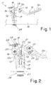
- figure 1 shows a braking device 11 intended to be mounted on a motorcycle to manually control vehicle braking.
- the device comprises a body 12 that can be fastened to a handlebar 14 of the motorcycle (shown schematically by a broken line in the illustration) and a lever 13 hinged to the body 12 by means of the pin 16.
- the lever 13 can be operated manually by the user of the motorcycle to be pushed in the direction of the arrow indicated in figure 1 and perform the braking action.
- the body 12 has fastening means 26 for fastening to the handlebar 14.
- the fastening means can include a sleeve portion 27, itself made using solutions well known in the sector.
- the device 11 comprises a hydraulic cylinder 17 having a chamber 24 (shown in figure 2 ) integral with the body 12 and intended to be connected to a hydraulic braking circuit of the vehicle (not shown in the illustration).
- the hydraulic circuit is connected to a braking caliper acting on the discs of the brake fitted to the wheels to be braked.
- the hydraulic cylinder 17 is connected to such hydraulic circuit according to prior art to control a braking pressure on the liquid (normally oil) contained in the braking circuit and in the caliper.
- the cylinder 17 comprises a piston 25 sliding inside the chamber 24.
- the piston is pushed by return action means into the idle position protracted towards the outside of the chamber 24.
- the return action means can be made with a spring inside the cylinder (not shown in the illustration), according to solutions known in themselves and easily imaginable by the technician of the sector.
- the chamber 24 of the hydraulic cylinder 17 is made up all one piece in the body 12 of the device.
- the fastening means 26 are arranged at a lower extremity of the cylinder 17.
- the body 12 has a pair of parallel flanges 12a onto which are hinged the lever 13 and the cam element 18.
- the illustration shows only one of the two flanges 12a, but it must be understood that the body 12 has two of these, defining an interspace in which are housed the lever 13 and the cam element 18.
- the piston 25 is mobile towards the inside of the chamber 24 under the action of the lever 13 to control the braking of the vehicle.
- the lever 13 acts on the piston to perform the braking action by means of a cam mechanism 20, 21.
- the cam mechanism comprises a cam surface 20 that is integral during use with the lever 13 and is suitable, during braking, for acting on a driven element 21 provided on a rod 19 connected to the piston 25, for example by screwing up.
- the cam surface 20, advantageously, is made on a cam element 18 constrained to the lever 13 with adjustable position.
- the cam element 18 is hinged to the lever 13.
- the device 11 comprises a registration dowel 28 fitted in a threaded hole of a pin 29 mounted turning on the lever 13.
- One extremity of the dowel 28 is accessible from outside to perform the registration, while the opposite extremity 30 is housed in a flared seat formed in the cam element 18 to push the cam element towards the driven element 21.
- the return action means of the piston 25, acting to push the piston in the protracted position from the chamber 24, allow constantly maintaining contact between the driven element 21 and the cam surface 20.
- the cam element 18 and the lever 13 are hinged on the same pin 16 constraining to the body 12. This permits making the structure of the device 11 particularly compact and inexpensive, limiting the number of components needed for its assembly.
- the hydraulic cylinder 17 preferably has an axis substantially at right angles to the extension of the lever 13, and to the axis of the handlebar 14 of the motorcycle.
- the cam surface 20 is arranged in intermediate position between the hinging 16 of the lever 13 to the body 12 and the portion 13a of the lever that can be operated by the vehicle user.
- the driven element 21 is made with a more or less spherical portion fastened to an extremity of the rod 19 integral with the cylinder piston.
- the spherical shape of the driven element 21 allows limiting the friction of the cam mechanism in an advantageous way.
- the cam surface 20 has a concave, arched profile, and can form a groove along which the spherical portion 21 slides during use.
- the cam surface 20 is preferably shaped so that the push exercised on the spherical portion 21 is always substantially parallel with the axis of the cylinder 17 for each angular position of the lever. This allows reducing the frictions to the utmost as well as any other dispersion of the force applied by the user in components transversal to the cylinder axis. Such circumstance permits making the braking action easier, limiting the effort required on the part of the user to reach the hydraulic pressures needed for braking.
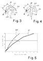
- the cam mechanism 20, 21 is preferably configured so the distance between the hinging 16 of the lever 13 to the body 12 and the point of application of the force from the lever to the cylinder piston drops on rotation of the lever 13 during braking. As is clearly shown in the figures 3 and 4 , at the start of braking, the lever arm “D" ( fig. 3 ) is greater than the lever arm “d” ( fig. 4 ) in braking condition.
- the lever 13 is formed of two parts 13a, 13b.
- the part 13a forms the portion of the lever that can be operated by the user, while the second part 13b is hinged to the body 12 of the device and has a cavity 31 inside which the cam element 18 is housed.
- the cavity 31 is formed between two parallel flanges of the portion 13b of the lever; the cutaway figure shows only the lower flange to allow viewing the cam element 18.
- the part 13a of the lever has an angular position adjustable with respect to the part 13b, so as to adapt to the requirements and to the habits of the motorcycle rider.
- the two parts 13a, 13b are hinged together by means of the pin 15.
- the adjustment of the position of the part 13a is done by means of the setscrew 22 which is fitted in a hole in the part 13a and has its head resting on the flange 23 of the part 13b of the lever.
- the figure 5 shows a graph that indicates the pattern of the stroke of the piston 25 according to the stroke of the lever 13, in the case of devices according to prior art (curve 40 broken line) and in the case of the device according to the invention (curve 41 unbroken line).
- the curve 41 is lower than the curve 40 because, the stroke of the lever 13 being equal, it is possible to achieve a longer stroke of the piston with respect to the prior art, thereby obtaining a more sensitive braking device.
- the solution of using a cam mechanism to transmit movement to the cylinder piston permits regulating and obtaining a desired braking sensitivity according to need.
- the pattern of piston movement according to lever rotation can be changed by adjusting the cam surface outline, obtaining a preset response of the braking device.
- the chart below shows pressure values of the braking liquid and of the piston stroke, correlated with the stroke of the lever and its rotation, using a braking device according to the described embodiment of the invention.
- a braking device has been provided that permits easily and flexibly regulating the stroke of the piston and the braking pressure obtainable according to the rotation angle of the lever.
- the device has a compact and inexpensive structure.
- the braking action can be made easier thanks to the fact that the lever arm of the force applied to the cylinder piston drops when the lever is rotated. Furthermore, the forces applied to the cylinder are almost always parallel with its axis, thus making it possible to reduce frictions to the utmost and avoid losing part of the force applied by the user in components transversal to the cylinder.
- the braking device according to the invention could also be applied to different types of vehicles, and not necessarily to a motorcycle.
Landscapes
- Physics & Mathematics (AREA)
- Fluid Mechanics (AREA)
- Engineering & Computer Science (AREA)
- Mechanical Engineering (AREA)
- Transmission Of Braking Force In Braking Systems (AREA)
- Steering Devices For Bicycles And Motorcycles (AREA)
- Braking Elements And Transmission Devices (AREA)
- Regulating Braking Force (AREA)
- Braking Arrangements (AREA)
Applications Claiming Priority (1)
| Application Number | Priority Date | Filing Date | Title |
|---|---|---|---|
| IT000346A ITMI20080346A1 (it) | 2008-02-29 | 2008-02-29 | "dispositivo di frenatura" |
Publications (2)
| Publication Number | Publication Date |
|---|---|
| EP2096025A2 true EP2096025A2 (fr) | 2009-09-02 |
| EP2096025A3 EP2096025A3 (fr) | 2010-04-14 |
Family
ID=40291736
Family Applications (1)
| Application Number | Title | Priority Date | Filing Date |
|---|---|---|---|
| EP09153891A Withdrawn EP2096025A3 (fr) | 2008-02-29 | 2009-02-27 | Dispositif de freinage |
Country Status (4)
| Country | Link |
|---|---|
| US (1) | US8281903B2 (fr) |
| EP (1) | EP2096025A3 (fr) |
| JP (1) | JP5300060B2 (fr) |
| IT (1) | ITMI20080346A1 (fr) |
Cited By (2)
| Publication number | Priority date | Publication date | Assignee | Title |
|---|---|---|---|---|
| DE102009039620A1 (de) * | 2009-09-01 | 2011-03-03 | Gustav Magenwirth Gmbh & Co. Kg | Gebervorrichtung für ein geschlossenes Hydrauliksystem lenkergeführter Fahrzeuge |
| CN110143253A (zh) * | 2019-05-21 | 2019-08-20 | 福建省福鼎市新龙机车部件有限公司 | 一种具有加热通风功能的可调摩托车刹车把 |
Families Citing this family (8)
| Publication number | Priority date | Publication date | Assignee | Title |
|---|---|---|---|---|
| US8255708B1 (en) | 2007-08-10 | 2012-08-28 | Marvell International Ltd. | Apparatuses and methods for power saving in USB devices |
| TWI385103B (zh) * | 2009-12-25 | 2013-02-11 | 林昌慧 | 全功率液壓煞車器 |
| US8863612B2 (en) * | 2011-08-22 | 2014-10-21 | Mon Spencer Owyang | Lever positioner assembly |
| IT201600111274A1 (it) | 2016-11-04 | 2018-05-04 | Freni Brembo Spa | Dispositivo a leva |
| US20200025208A1 (en) * | 2018-07-23 | 2020-01-23 | Deere & Company | Variable pitch fan assembly with blade pitch indication |
| GB2583123B (en) | 2019-04-17 | 2021-04-14 | Rollersafe As | Remote operating lever unit for operating brake unit, brake system, and method of repositioning lever |
| TWI742650B (zh) * | 2020-05-08 | 2021-10-11 | 弘家金屬工業股份有限公司 | 煞車把手結構 |
| TWI737501B (zh) * | 2020-09-25 | 2021-08-21 | 彥豪金屬工業股份有限公司 | 自行車煞車駐車裝置 |
Citations (3)
| Publication number | Priority date | Publication date | Assignee | Title |
|---|---|---|---|---|
| US3554334A (en) * | 1968-06-17 | 1971-01-12 | Keizo Shimano | Hydraulic bicycle brake system |
| DE2530745A1 (de) * | 1975-07-10 | 1977-01-20 | Magenwirth Kg Gustav | Gasdrehgriff fuer motorisierte zweiradfahrzeuge mit bremshydraulik |
| EP1351847A1 (fr) * | 2001-03-02 | 2003-10-15 | Freni Brembo S.p.A. | Maitre-cylindre pour motocyclette/bicyclette ou analogue, frein ou embrayage |
Family Cites Families (23)
| Publication number | Priority date | Publication date | Assignee | Title |
|---|---|---|---|---|
| GB8421830D0 (en) * | 1984-08-29 | 1984-10-03 | Automotive Prod Plc | Hydraulic master cylinder |
| JPH0777877B2 (ja) * | 1985-12-06 | 1995-08-23 | 本田技研工業株式会社 | 車両用アジャスタブル操作レバー |
| JPS6389893U (fr) * | 1986-12-01 | 1988-06-10 | ||
| KR900008424B1 (ko) * | 1987-06-05 | 1990-11-20 | 닛신 고오교오 가부시끼가이샤 | 차량용 레버장치 |
| JPH01237282A (ja) * | 1988-03-18 | 1989-09-21 | Suzuki Motor Co Ltd | 自動2輪車などの操作レバー装置 |
| JPH0331054A (ja) | 1989-06-27 | 1991-02-08 | Nissin Kogyo Kk | 車両用液圧マスタシリンダの操作レバー |
| JPH041034Y2 (fr) * | 1989-09-13 | 1992-01-14 | Nissin Kogyo Kk | |
| JPH0729033Y2 (ja) * | 1990-07-13 | 1995-07-05 | 日信工業株式会社 | 車両用マスタシリンダ |
| JP3393311B2 (ja) * | 1993-12-27 | 2003-04-07 | 日信工業株式会社 | 車両用液圧マスタシリンダ装置 |
| JPH09142360A (ja) * | 1995-11-20 | 1997-06-03 | Suzuki Motor Corp | 油圧ブレーキのレバー装置 |
| JPH10230886A (ja) * | 1997-02-20 | 1998-09-02 | Nissin Kogyo Kk | バーハンドル車両用液圧マスタシリンダの操作レバー |
| JP4249868B2 (ja) * | 1999-12-16 | 2009-04-08 | 日信工業株式会社 | バーハンドル車両用操作レバーの握り代調整機構 |
| JP2001180559A (ja) * | 1999-12-27 | 2001-07-03 | Nissin Kogyo Co Ltd | バーハンドル車両用液圧マスタシリンダ装置 |
| EP1160152B1 (fr) * | 2000-06-02 | 2005-12-07 | Freni Brembo S.p.A. | Dispositif pour ajuster la position du levier de fonctionnement d'un vérin hydraulique |
| US20030121736A1 (en) * | 2001-12-28 | 2003-07-03 | Avid, L.L.C. | Master cylinder lever for a hydraulic disc brake having a backpack reservoir |
| US6804961B2 (en) * | 2001-12-28 | 2004-10-19 | Sram Corporation | Master cylinder lever for a hydraulic disk brake having on the fly dead-band adjustment |
| EP1439116B1 (fr) | 2002-12-27 | 2007-07-18 | Nissin Kogyo Co., Ltd. | Maître-cylindre hydraulique pour véhicule avec guidon |
| AU2003292533A1 (en) | 2003-11-20 | 2005-06-08 | Freni Brembo S.P.A | Position adjustment device for an operation lever of an hydraulic actuator |
| JP4785115B2 (ja) * | 2004-05-14 | 2011-10-05 | 本田技研工業株式会社 | 油圧操作用レバー装置 |
| US7377367B2 (en) | 2005-02-18 | 2008-05-27 | Shimano Inc. | Hydraulic disc brake lever assembly |
| EP1733958B9 (fr) * | 2005-06-14 | 2009-10-14 | Shimano Inc. | Dispositif d'actionnement pour frein hydraulique |
| ITMI20052240A1 (it) * | 2005-11-23 | 2007-05-24 | Freni Brembo Spa | Dispositivo a leva per l'azionamento di un attuatore idraulico |
| US7757821B2 (en) * | 2006-06-09 | 2010-07-20 | Shimano Inc. | Bicycle hydraulic brake actuation device |
-
2008
- 2008-02-29 IT IT000346A patent/ITMI20080346A1/it unknown
-
2009
- 2009-02-27 EP EP09153891A patent/EP2096025A3/fr not_active Withdrawn
- 2009-02-27 US US12/379,783 patent/US8281903B2/en not_active Expired - Fee Related
- 2009-03-02 JP JP2009047643A patent/JP5300060B2/ja not_active Expired - Fee Related
Patent Citations (3)
| Publication number | Priority date | Publication date | Assignee | Title |
|---|---|---|---|---|
| US3554334A (en) * | 1968-06-17 | 1971-01-12 | Keizo Shimano | Hydraulic bicycle brake system |
| DE2530745A1 (de) * | 1975-07-10 | 1977-01-20 | Magenwirth Kg Gustav | Gasdrehgriff fuer motorisierte zweiradfahrzeuge mit bremshydraulik |
| EP1351847A1 (fr) * | 2001-03-02 | 2003-10-15 | Freni Brembo S.p.A. | Maitre-cylindre pour motocyclette/bicyclette ou analogue, frein ou embrayage |
Cited By (4)
| Publication number | Priority date | Publication date | Assignee | Title |
|---|---|---|---|---|
| DE102009039620A1 (de) * | 2009-09-01 | 2011-03-03 | Gustav Magenwirth Gmbh & Co. Kg | Gebervorrichtung für ein geschlossenes Hydrauliksystem lenkergeführter Fahrzeuge |
| US8398106B2 (en) | 2009-09-01 | 2013-03-19 | Gustov Magenwirth GmbH & Co. KG | Master device for a closed hydraulic system of handlebar-steered vehicles |
| US8511700B1 (en) | 2009-09-01 | 2013-08-20 | Gustav Magenwirth Gmbh & Co. Kg | Master device for a closed hydraulic system of handlebar-steered vehicles |
| CN110143253A (zh) * | 2019-05-21 | 2019-08-20 | 福建省福鼎市新龙机车部件有限公司 | 一种具有加热通风功能的可调摩托车刹车把 |
Also Published As
| Publication number | Publication date |
|---|---|
| ITMI20080346A1 (it) | 2009-09-01 |
| US20090229927A1 (en) | 2009-09-17 |
| EP2096025A3 (fr) | 2010-04-14 |
| JP5300060B2 (ja) | 2013-09-25 |
| JP2009208767A (ja) | 2009-09-17 |
| US8281903B2 (en) | 2012-10-09 |
Similar Documents
| Publication | Publication Date | Title |
|---|---|---|
| EP2096025A2 (fr) | Dispositif de freinage | |
| TWI582005B (zh) | 用於自行車之刹車系統的可變比率總成 | |
| US8678144B2 (en) | Hydraulic caliper brake for a bicycle | |
| US20070056818A1 (en) | Apparatus for controlling hydraulic brakes in bicycles, motorbicycles and the like | |
| US4635442A (en) | Hydraulic master cylinder assembly | |
| EP2840016A1 (fr) | Appareil de libération rapide pour frein à mâchoires hydrauliques de bicyclette | |
| EP1514791B1 (fr) | Dispositif de commande de freins hydrauliques pour bicyclettes, motocyclettes et véhicules similaires | |
| US9840304B2 (en) | Hydraulic brake actuation device | |
| WO1994021510A1 (fr) | Mecanisme d'actionnement d'un maître cylindre hydraulique | |
| EP2694359B1 (fr) | Pompe pour frein ou embrayage pour véhicule guidé par un guidon | |
| US12005992B2 (en) | Hydraulic operating device for human-powered vehicle | |
| JP6533646B2 (ja) | オレオ式の流体圧制御部が一体化した自転車のハンドルバーアセンブリ | |
| CN112770956A (zh) | 具有支撑在压力件上的联接杆的线控转向式转向传动装置 | |
| US9233731B1 (en) | Bicycle rim brake | |
| US8739940B2 (en) | Interface member for a bicycle brake | |
| US10259521B2 (en) | Bicycle brake and method for constructing the profile of a surface portion of a lever of said brake | |
| US8342295B2 (en) | Return spring apparatus for a bicycle brake | |
| CN101356084A (zh) | 踏板操作量检测设备 | |
| US20120222922A1 (en) | Hydraulic rim brake for a bicycle | |
| EP1106463B1 (fr) | Dispositif pour doser la décélération d'un véhicule | |
| BE441421A (fr) | ||
| JP2500962Y2 (ja) | プッシュロッド | |
| FR2660274A1 (fr) | Procede de reglage de la valeur du saut d'un servomoteur d'assistance au freinage. | |
| JP2018525587A (ja) | ガススプリングをトリガするための装置 | |
| FR2829544A1 (fr) | Cylindre de frein a actionnement mecanique et hydraulique a neutralisation de reglage optimise et frein comportant un tel cylindre |
Legal Events
| Date | Code | Title | Description |
|---|---|---|---|
| PUAI | Public reference made under article 153(3) epc to a published international application that has entered the european phase |
Free format text: ORIGINAL CODE: 0009012 |
|
| AK | Designated contracting states |
Kind code of ref document: A2 Designated state(s): AT BE BG CH CY CZ DE DK EE ES FI FR GB GR HR HU IE IS IT LI LT LU LV MC MK MT NL NO PL PT RO SE SI SK TR |
|
| AX | Request for extension of the european patent |
Extension state: AL BA RS |
|
| PUAL | Search report despatched |
Free format text: ORIGINAL CODE: 0009013 |
|
| AK | Designated contracting states |
Kind code of ref document: A3 Designated state(s): AT BE BG CH CY CZ DE DK EE ES FI FR GB GR HR HU IE IS IT LI LT LU LV MC MK MT NL NO PL PT RO SE SI SK TR |
|
| AX | Request for extension of the european patent |
Extension state: AL BA RS |
|
| 17P | Request for examination filed |
Effective date: 20101001 |
|
| 17Q | First examination report despatched |
Effective date: 20101027 |
|
| AKX | Designation fees paid |
Designated state(s): AT BE BG CH CY CZ DE DK EE ES FI FR GB GR HR HU IE IS IT LI LT LU LV MC MK MT NL NO PL PT RO SE SI SK TR |
|
| STAA | Information on the status of an ep patent application or granted ep patent |
Free format text: STATUS: THE APPLICATION IS DEEMED TO BE WITHDRAWN |
|
| 18D | Application deemed to be withdrawn |
Effective date: 20130312 |