EP2099576B1 - Hohle strahldüse für das stranggiessen - Google Patents
Hohle strahldüse für das stranggiessen Download PDFInfo
- Publication number
- EP2099576B1 EP2099576B1 EP07800357A EP07800357A EP2099576B1 EP 2099576 B1 EP2099576 B1 EP 2099576B1 EP 07800357 A EP07800357 A EP 07800357A EP 07800357 A EP07800357 A EP 07800357A EP 2099576 B1 EP2099576 B1 EP 2099576B1
- Authority
- EP
- European Patent Office
- Prior art keywords
- nozzle
- powder
- pipe
- installation according
- injecting
- Prior art date
- Legal status (The legal status is an assumption and is not a legal conclusion. Google has not performed a legal analysis and makes no representation as to the accuracy of the status listed.)
- Active
Links
Images

Classifications
-
- B—PERFORMING OPERATIONS; TRANSPORTING
- B22—CASTING; POWDER METALLURGY
- B22D—CASTING OF METALS; CASTING OF OTHER SUBSTANCES BY THE SAME PROCESSES OR DEVICES
- B22D11/00—Continuous casting of metals, i.e. casting in indefinite lengths
- B22D11/10—Supplying or treating molten metal
-
- B—PERFORMING OPERATIONS; TRANSPORTING
- B22—CASTING; POWDER METALLURGY
- B22D—CASTING OF METALS; CASTING OF OTHER SUBSTANCES BY THE SAME PROCESSES OR DEVICES
- B22D41/00—Casting melt-holding vessels, e.g. ladles, tundishes, cups or the like
- B22D41/50—Pouring-nozzles
- B22D41/58—Pouring-nozzles with gas injecting means
-
- B—PERFORMING OPERATIONS; TRANSPORTING
- B22—CASTING; POWDER METALLURGY
- B22D—CASTING OF METALS; CASTING OF OTHER SUBSTANCES BY THE SAME PROCESSES OR DEVICES
- B22D11/00—Continuous casting of metals, i.e. casting in indefinite lengths
- B22D11/10—Supplying or treating molten metal
- B22D11/108—Feeding additives, powders, or the like
-
- B—PERFORMING OPERATIONS; TRANSPORTING
- B22—CASTING; POWDER METALLURGY
- B22D—CASTING OF METALS; CASTING OF OTHER SUBSTANCES BY THE SAME PROCESSES OR DEVICES
- B22D41/00—Casting melt-holding vessels, e.g. ladles, tundishes, cups or the like
- B22D41/50—Pouring-nozzles
Definitions
- the present invention relates to an improvement of the device and method for casting a molten metal, in particular steel, in a continuous casting mold, using a hollow jet nozzle, where the metallic material is finely divided is injected into the interior volume of the hollow jet, the latter being maintained by circulation of a flow of non-oxidizing gas such as argon.
- the molten steel is introduced into the mold by means of at least one nozzle, that is to say a generally tubular element arranged between the tundish and the mold. .
- the lower end of the nozzle is usually provided with one or two outlets located in the axis of the nozzle or laterally, and opens under the free level of liquid steel present in the mold.
- a protective gas such as argon under the distribution dome of the steel ensures the formation and maintenance of the hollow jet inside the nozzle.
- the introduction of the protective gas under pressure in the conduit causes an overpressure which prevents any entrainment of air by the liquid steel, which would lead to the oxidation thereof or to the formation of alumina with clogging. the nozzle.
- the injection of the powder is carried out by pneumatic transport under argon through the refractory dome creating the hollow jet.
- the document WO-2006/096942 describes an installation and method for injection of technical ceramic nanoparticles into the hollow jet created in a HJN nozzle.
- the injection of the nanoparticles can be carried out by means of a mechanical transport device such as a worm.
- a mechanical transport device such as a worm.
- this document does not mention, for this embodiment, the positioning and the characteristics that the auger device must possess to be operational, nor how the non-oxidizing gas necessary for the establishment of the hollow jet and the protection of the casting metal is conveyed into the nozzle, in connection with the injection of nanoparticles.
- the flow rate of the carrier gas increases depending on the amount of powder to be injected by the existing system.
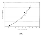
- the figure 1 shows an example of a relationship between the powder flow rate and the argon flow rate for an iron powder with a particle size of between 100 and 200 ⁇ m injected into a tube 10 mm in diameter. This therefore limits the amount of injectable powder in the product, especially in the case of continuous slab casting where the powder flow rates must be greater than for the casting of billets.
- the maximum quantity allowed gas is 15 Nl / min
- the rate of powder injected is limited to 13 kg / min.
- the present invention aims to provide a solution that makes it possible to overcome the disadvantages of the state of the art.
- the invention aims to allow the injection of a quantity of metal powder into a HJN nozzle at a high flow rate while maintaining a flow rate of the protective gas of the hollow jet acceptable in intensity for stable operation of the casting continuously.
- a first object of the present invention relates to a continuous casting plant for the flow of liquid steel from a tundish in an ingot mold through a hollow jet nozzle, called the HJN nozzle, comprising mainly, if it is described in a vertical position and considered in the direction of progression of the liquid steel from top to bottom, a vertical pipe terminated by an upper cover having an inlet for the liquid steel from the tundish and a lower base having at least one outlet, said duct comprising in its upper part a distributor member disposed substantially at the inlet of said vertical duct and comprising a deflector or dome for diverting the incoming metal to the side walls of the nozzle, said nozzle also comprising injection means of metal powder or solid metal finely divided under said dome in an injection zone and non-oxidizing gas injection means for the establishment and maintenance of the hollow jet, characterized in that the powder injection means are independent and physically separate from the injection means of the non-oxidizing gas, so that in operation the non-oxidizing gas is not used as a vector for powder injection.
- said installation comprises on the one hand a conduit for the incoming flow of non-oxidizing gas in the nozzle at a first orifice, possibly terminated by an injector located at this first orifice and its flow measuring device. and pressure and secondly, separately, a conduit for supplying the powder nozzle, at a second orifice, optionally terminated by an injector located at this second orifice, a powder reservoir or finely divided particles and its weight measuring device.
- the powder injection means comprise mechanical means such as a worm device.
- the worm gear device is disposed between the bottom of the tundish and the upper cover of the nozzle HJN.
- the conduit for the supply of the powder nozzle opens under the distribution dome, at least a portion of this conduit being arranged in the distribution dome with a non-zero slope.
- the installation is provided with means for controlling the flow of powder, said means preferably comprising a servocontrol of the rotation of the worm to a continuous measurement of the weight of the powder reservoir.
- the powder injection means are maintained under an inert atmosphere.
- the non-oxidizing gas comprises argon and said metal powder is an iron or ferroalloy powder.
- the figure 1 graphically represents the relationship between the flow of injected metal powder and the flow of argon in which it is in suspension, for injection into a continuous jet casting nozzle.
- the figure 2 represents an embodiment of an exemplary device according to the state of the art.
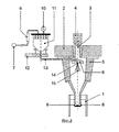
- the figure 3 represents a preferred embodiment of the device according to the present invention.
- the figure 2 shows a casting device according to the state of the art (patent BE 1014063 ), mounted between a continuous casting mold 1 and a pouring ladle or a tundish 2 comprising an outlet conduit 3.
- the outlet conduit 3 is provided with a flow regulator, such as a stopper 4 or a sliding drawer.
- the upper base of the cylinder is in contact with the conduit 3. This base is provided with a hole corresponding to the inner orifice of the conduit.
- the nozzle 5 comprises at its lower part at least one communication port 8 allowing the passage of steel to the mold.
- a dome-shaped distribution member 6 In the upper part of the nozzle 5 is arranged a dome-shaped distribution member 6, whose upper surface is slightly sloping, preferably greater than 10 °, relative to the horizontal.
- An injection device is arranged to introduce finely divided solid particles or powder 15 under the dome 6, using a non-oxidizing gas as a carrier.
- This device also comprises an inlet stream of argon 7 and its flow measuring device 9 and pressure device 10, a powder container or finely divided particles 11 and its weight measuring device 12, and finally a feed pipe in the nozzle 13, and an injector 14.
- the subject of the present invention is a device which makes it possible to separate the quantity of powder injected into the hollow jet nozzle from the quantity of argon added for the creation and maintenance of the hollow jet.
- the device of the invention shown schematically on the figure 3 thus comprises means for separating the gas supply and the powder injection.
- the supply of metal powder is ensured by means of a supply line 13, for example passing through the distributing dome 6, opening under it at an orifice 14, possibly provided with an injector of appropriate form not shown, and provided with a worm 13A.
- a supply line 13 for example passing through the distributing dome 6, opening under it at an orifice 14, possibly provided with an injector of appropriate form not shown, and provided with a worm 13A.
- Argon injection, independent of the injection of powder, intended solely to maintain the hollow jet is provided by an additional conduit 16 terminated by an orifice 17, optionally provided with an injector of appropriate shape not shown, opening for example also under the distribution dome 6.
- a regulation of the powder flow rate will be ensured by a control of the speed of rotation of the screw, slaved to a continuous measurement of the weight of the powder reservoir.
- the entire injection system is maintained under an inert atmosphere of argon to prevent oxygen scavenging in the steel.
Landscapes
- Engineering & Computer Science (AREA)
- Mechanical Engineering (AREA)
- Continuous Casting (AREA)
- Nozzles (AREA)
Claims (12)
- Anlage für das Stranggießen für den Durchfluss von flüssigem Stahl, ausgehend von einem Verteilerkorb (2) in eine Stranggusskokille (1) über ein Gießrohr mit Hohlstrahl, das sog. HJN-Gießrohr; die Anlage umfasst im Wesentlichen, wenn sie in vertikaler Position und in Verlaufsrichtung des flüssigen Stahls von oben nach unten beschrieben wird, eine vertikale Leitung (5), die durch einen oberen Deckel (5A) eingegrenzt wird, der eine Eingangsmündung für den flüssigen Stahl ausgehend von dem Verteilerkorb (2) sowie eine untere Grundfläche umfasst, die mindestens eine Ausgangsmündung beinhaltet (8), wobei die besagte Leitung (5) in ihrem oberen Bereich ein Verteilerelement, das in deutlicher Weise am Eingang der besagten vertikalen Leitung (5) angeordnet ist und einen Ableiter bzw. eine Kuppel (6) enthält, der/die es ermöglicht, das eintretende Metall an die Seitenwände des Gießrohrs abzuleiten, beinhaltet, wobei das besagte Gießrohr gleichermaßen Hilfsmittel zur Einspritzung (13, 13A, 14) des Metallpulvers bzw. des festen fein zerstäubten Metallmaterials, die eine Vorrichtung mit Endlosgewinde (13A) unterhalb der besagten Kuppel(6) in einem Einspritzbereich (15) sowie weitere Vorrichtungen für die Einspritzung eines nicht oxidierenden Gases (16, 17) für die Erschaffung und die Bewahrung des Hohlstrahls enthalten, beinhaltet und wobei die Anlage dadurch gekennzeichnet ist, dass die Hilfsmittel für die Einspritzung des Pulvers unabhängig und physikalisch von den Vorrichtungen zur Einspritzung des nicht oxidierenden Gases (16, 17) getrennt sind; die Vorrichtung mit Endlosgewinde (13A) ist hierbei zwischen dem Boden des Verteilerkorbs(2) und dem oberen Deckel(5A) des HJN-Gießrohrs angeordnet.
- Anlage entsprechend dem Anspruch 1, dadurch gekennzeichnet, dass sie eine Leitung (16) für den eintretenden Strom des nicht oxidierenden Gases (7) in dem Gießrohr, auf der Ebene einer ersten Mündung (17) und seiner Vorrichtung zur Strömungs- (9) und zur Druckmessung (10) enthält.
- Anlage entsprechend dem Anspruch 2, dadurch gekennzeichnet, dass die besagte Leitung (16) für den eintretenden Strom des nicht oxidierenden Gases durch eine an der ersten Mündung (17) gelegene Einspritzdüse begrenzt wird.
- Anlage gemäß den Ansprüchen 1, 2 oder 3, dadurch gekennzeichnet, dass sie eine gesonderte Leitung (13) für die Versorgung des Pulver-Gießrohrs auf der Ebene einer zweiten Mündung (14), einen Behälter für Pulver oder fein zerstäubte Partikel (11) und seine Vorrichtung zur Gewichtsmessung (12) beinhaltet.
- Anlage gemäß dem Anspruch 4, dadurch gekennzeichnet, dass die besagte Leitung (13) für die Versorgung des Pulver-Gießrohrs durch eine an der zweiten Mündung gelegene Einspritzdüse (14) begrenzt wird.
- Anlage gemäß dem Anspruch 4, dadurch gekennzeichnet, dass die Leitung für die Versorgung des Pulver-Gießrohrs (13) unterhalb der Verteilerkuppel (6) mündet; hierbei ist zumindest ein Teil dieser Leitung in der Verteilerkuppel(6) mit einem Gefälle von nicht gleich Null angeordnet.
- Anlage gemäß dem Anspruch 1, dadurch gekennzeichnet, dass sie mit Hilfsmitteln zur Regelung der Durchflussmenge des Pulvers ausgestattet ist.
- Anlage gemäß dem Anspruch 7, dadurch gekennzeichnet, dass die besagten Hilfsmittel eine Steuerung für die Rotation des Endlosgewindes (13A) mit einer kontinuierlichen Messung des Gewichts des Pulverbehälters (11) beinhalten.
- Anlage gemäß irgendeinem der vorherigen Ansprüche, dadurch gekennzeichnet, dass die Hilfsmittel zur Pulvereinspritzung (13, 13A, 14) unter einer inerten Atmosphäre gehalten werden.
- Anlage gemäß irgendeinem der vorherigen Ansprüche, dadurch gekennzeichnet, dass das nicht oxidierende Gas Argon enthält.
- Anlage gemäß irgendeinem der vorherigen Ansprüche, dadurch gekennzeichnet, dass es sich bei dem besagten Metallpulver um ein Eisenpulver bzw. um ein Pulver aus einer Eisenlegierung handelt.
- Verfahren für das Stranggießen von Stahl in einem Hohlstrahl, vorzugsweise in Form von flachen oder langen Produkten, mithilfe der Anlage gemäß irgendeinem der vorherigen Ansprüche, das die folgenden Schritte umfasst:- Gießen eines Stahls auf geschmolzener Basis aus einem Verteilerkorb (2) in eine Stranggusskokille (1) über das HJN-Gießrohr (5) ;- Erschaffen und Bewahren eines Hohlstrahls ausgehend von einer ersten Leitung (16) eines nicht oxidierenden Gases wie z.B. Argon mit einer Durchflussmenge, die einen Wert von 15 Nl/Min. nicht überschreitet ;- Einspritzung durch eine zweite Leitung (13), die unabhängig von der ersten Leitung ist und eine Vorrichtung mit Endlosgewinde (13A) beinhaltet, eines fein zerstäubten festen oder pulverförmigen Metallmaterials in den hohlen Bereich des Gießrohrs unterhalb des Verteilerelements (6); das besagte fein zerstäubte feste oder pulverförmige Material vermischt sich hierbei mit dem Stahl am Ende des Einspritzbereichs in dem Gießrohr bzw. im Mischbereich des Gießrohrs und der Stranggusskokille.
Priority Applications (2)
| Application Number | Priority Date | Filing Date | Title |
|---|---|---|---|
| SI200730287T SI2099576T1 (sl) | 2006-12-12 | 2007-09-03 | Votla razpršilna šoba za kontinuirano litje jekla |
| PL07800357T PL2099576T3 (pl) | 2006-12-12 | 2007-09-03 | Wylew kadziowy z pustym wewnątrz strumieniem do odlewania ciągłego stali |
Applications Claiming Priority (2)
| Application Number | Priority Date | Filing Date | Title |
|---|---|---|---|
| BE2006/0609A BE1017392A3 (fr) | 2006-12-12 | 2006-12-12 | Busette a jet creux pour coulee continue d'acier. |
| PCT/BE2007/000100 WO2008070935A1 (fr) | 2006-12-12 | 2007-09-03 | Busette a jet creux pour coulee continue d'acier |
Publications (3)
| Publication Number | Publication Date |
|---|---|
| EP2099576A1 EP2099576A1 (de) | 2009-09-16 |
| EP2099576B1 true EP2099576B1 (de) | 2010-05-19 |
| EP2099576B8 EP2099576B8 (de) | 2010-07-21 |
Family
ID=37964317
Family Applications (1)
| Application Number | Title | Priority Date | Filing Date |
|---|---|---|---|
| EP07800357A Active EP2099576B8 (de) | 2006-12-12 | 2007-09-03 | Hohle strahldüse für das stranggiessen |
Country Status (10)
| Country | Link |
|---|---|
| EP (1) | EP2099576B8 (de) |
| KR (1) | KR101454311B1 (de) |
| AT (1) | ATE468188T1 (de) |
| BE (1) | BE1017392A3 (de) |
| BR (1) | BRPI0718348B1 (de) |
| DE (1) | DE602007006689D1 (de) |
| ES (1) | ES2343979T3 (de) |
| PL (1) | PL2099576T3 (de) |
| SI (1) | SI2099576T1 (de) |
| WO (1) | WO2008070935A1 (de) |
Cited By (7)
| Publication number | Priority date | Publication date | Assignee | Title |
|---|---|---|---|---|
| WO2013144668A1 (en) | 2012-03-28 | 2013-10-03 | Arcelormittal Investigacion Y Desarrollo Sl | Continuous casting process of metal |
| US9498822B2 (en) | 2012-03-28 | 2016-11-22 | Arcelormittal Investigacion Y Desarrollo, S.L. | Continuous casting equipment |
| CN111451462A (zh) * | 2020-04-09 | 2020-07-28 | 苏州大学 | 利用浸入式水口喷吹镁粉细化连铸坯凝固组织的方法 |
| CN111496240A (zh) * | 2020-06-24 | 2020-08-07 | 攀钢集团攀枝花钢铁研究院有限公司 | 用于连铸的浸入式水口 |
| CN111570782A (zh) * | 2020-06-24 | 2020-08-25 | 攀钢集团攀枝花钢铁研究院有限公司 | 连铸浸入式水口 |
| WO2025093902A1 (en) * | 2023-10-30 | 2025-05-08 | Arcelormittal | Method of continuous casting of a composite metallic product |
| WO2025093900A1 (en) * | 2023-10-30 | 2025-05-08 | Arcelormittal | Method of continuous casting of a composite metallic product |
Families Citing this family (7)
| Publication number | Priority date | Publication date | Assignee | Title |
|---|---|---|---|---|
| KR101443348B1 (ko) * | 2013-03-28 | 2014-09-19 | 현대제철 주식회사 | 용강 탈황제 공급장치 |
| EP3056304A1 (de) * | 2015-02-16 | 2016-08-17 | Uvån Holding AB | Düsen- und Zwischenpfannenanordnung zur Granulierung von geschmolzenem Material |
| WO2024127076A1 (en) * | 2022-12-16 | 2024-06-20 | Arcelormittal | Continuous casting equipment |
| WO2024127073A1 (en) * | 2022-12-16 | 2024-06-20 | Arcelormittal | Continuous casting equipment |
| WO2024127075A1 (en) * | 2022-12-16 | 2024-06-20 | Arcelormittal | Continuous casting equipment |
| WO2024161178A1 (en) * | 2023-01-31 | 2024-08-08 | Arcelormittal | Continuous casting equipment |
| WO2024201113A1 (en) * | 2023-03-31 | 2024-10-03 | Arcelormittal | Continuous casting equipment |
Family Cites Families (9)
| Publication number | Priority date | Publication date | Assignee | Title |
|---|---|---|---|---|
| FR2150591A1 (en) * | 1971-08-27 | 1973-04-13 | Air Liquide | Cooling of molten metal - by addition of particles of the same metal(s) at a considerably lower temp |
| IT1116425B (it) * | 1977-04-18 | 1986-02-10 | Centro Speriment Metallurg | Sistema di raffreddamento e alligazione della massa fusa nella colata continua dell'acciaio |
| JPS5873713A (ja) * | 1981-10-27 | 1983-05-04 | Nippon Steel Corp | 強脱酸元素添加鋼の製造方法 |
| EP0269180B1 (de) * | 1986-11-26 | 1992-01-02 | CENTRE DE RECHERCHES METALLURGIQUES CENTRUM VOOR RESEARCH IN DE METALLURGIE Association sans but lucratif | Vorrichtung zum Giessen eines pastenartigen Metalles |
| BE1004121A6 (fr) * | 1990-05-04 | 1992-09-29 | Lahaut Hugues | Dispositif pour la coulee d'un metal et procede d'utilisation de ce dispositif. |
| BE1006567A6 (fr) * | 1992-12-28 | 1994-10-18 | Centre Rech Metallurgique | Procede de coulee d'un metal en phase pateuse. |
| BE1013745A3 (fr) * | 2000-10-10 | 2002-07-02 | Ct De Rech S Metallurg Ass San | Procede et dispositif pour couler en continu de l'acier a composition chimique mixte. |
| BE1014063A3 (fr) * | 2001-03-22 | 2003-03-04 | Ct De Rech S Metallurg Ass San | Procede et dispositif pour couler en continu de l'acier presentant des oxydes fins. |
| BE1016550A3 (fr) * | 2005-03-16 | 2007-01-09 | Ct Rech Metallurgiques Asbl | Procede pour couler en continu un metal a resistance mecanique amelioree et produit obtenu par le procede. |
-
2006
- 2006-12-12 BE BE2006/0609A patent/BE1017392A3/fr not_active IP Right Cessation
-
2007
- 2007-09-03 DE DE602007006689T patent/DE602007006689D1/de active Active
- 2007-09-03 EP EP07800357A patent/EP2099576B8/de active Active
- 2007-09-03 PL PL07800357T patent/PL2099576T3/pl unknown
- 2007-09-03 BR BRPI0718348A patent/BRPI0718348B1/pt not_active IP Right Cessation
- 2007-09-03 ES ES07800357T patent/ES2343979T3/es active Active
- 2007-09-03 AT AT07800357T patent/ATE468188T1/de not_active IP Right Cessation
- 2007-09-03 SI SI200730287T patent/SI2099576T1/sl unknown
- 2007-09-03 KR KR1020097012282A patent/KR101454311B1/ko not_active Expired - Fee Related
- 2007-09-03 WO PCT/BE2007/000100 patent/WO2008070935A1/fr not_active Ceased
Cited By (10)
| Publication number | Priority date | Publication date | Assignee | Title |
|---|---|---|---|---|
| WO2013144668A1 (en) | 2012-03-28 | 2013-10-03 | Arcelormittal Investigacion Y Desarrollo Sl | Continuous casting process of metal |
| CN104220190A (zh) * | 2012-03-28 | 2014-12-17 | 安赛乐米塔尔研发有限公司 | 金属的连续铸造方法 |
| US9498822B2 (en) | 2012-03-28 | 2016-11-22 | Arcelormittal Investigacion Y Desarrollo, S.L. | Continuous casting equipment |
| US12157165B2 (en) | 2012-03-28 | 2024-12-03 | Arcelormittal | Continuous casting process of metal |
| CN111451462A (zh) * | 2020-04-09 | 2020-07-28 | 苏州大学 | 利用浸入式水口喷吹镁粉细化连铸坯凝固组织的方法 |
| CN111451462B (zh) * | 2020-04-09 | 2021-09-28 | 苏州大学 | 利用浸入式水口喷吹镁粉细化连铸坯凝固组织的方法 |
| CN111496240A (zh) * | 2020-06-24 | 2020-08-07 | 攀钢集团攀枝花钢铁研究院有限公司 | 用于连铸的浸入式水口 |
| CN111570782A (zh) * | 2020-06-24 | 2020-08-25 | 攀钢集团攀枝花钢铁研究院有限公司 | 连铸浸入式水口 |
| WO2025093902A1 (en) * | 2023-10-30 | 2025-05-08 | Arcelormittal | Method of continuous casting of a composite metallic product |
| WO2025093900A1 (en) * | 2023-10-30 | 2025-05-08 | Arcelormittal | Method of continuous casting of a composite metallic product |
Also Published As
| Publication number | Publication date |
|---|---|
| DE602007006689D1 (de) | 2010-07-01 |
| EP2099576B8 (de) | 2010-07-21 |
| ES2343979T3 (es) | 2010-08-13 |
| BRPI0718348B1 (pt) | 2016-03-29 |
| BE1017392A3 (fr) | 2008-08-05 |
| KR101454311B1 (ko) | 2014-10-23 |
| ATE468188T1 (de) | 2010-06-15 |
| PL2099576T3 (pl) | 2010-10-29 |
| EP2099576A1 (de) | 2009-09-16 |
| BRPI0718348A2 (pt) | 2013-11-26 |
| SI2099576T1 (sl) | 2010-08-31 |
| KR20090095590A (ko) | 2009-09-09 |
| WO2008070935A1 (fr) | 2008-06-19 |
Similar Documents
| Publication | Publication Date | Title |
|---|---|---|
| EP2099576A1 (de) | Hohle strahldüse für das stranggiessen | |
| EP0620062B1 (de) | Stranggiessverfahren mit Kokillen-Aufsatz und Kokille zur Anwendung | |
| BE1013745A3 (fr) | Procede et dispositif pour couler en continu de l'acier a composition chimique mixte. | |
| KR101234171B1 (ko) | 합금주조장치 | |
| FR2554030A1 (fr) | Dispositif de decharge de metal fondu | |
| FR2546783A1 (fr) | Procede et dispositif de traitement d'un metal liquide moule sous basse pression, notamment pour l'inoculation de la fonte | |
| EP0743114B2 (de) | Verfahren zur Schmierung der Wände einer Stranggusskokille für Metalle und Kokille zur Durchführung dieses Verfahrens | |
| FR2611151A1 (fr) | Dispositif de prechauffage et/ou d'obturation et de debouchage d'un orifice de coulee et procede pour sa mise en oeuvre | |
| BE1012037A3 (fr) | Busette pour couler en continu de l'acier. | |
| FR2555080A1 (fr) | Procede et appareil pour eviter la formation d'un tourbillon dans un recipient metallurgique de coulee a sortie par le fond | |
| BE1014063A3 (fr) | Procede et dispositif pour couler en continu de l'acier presentant des oxydes fins. | |
| EP0370934B1 (de) | Verfahren und Einrichtung zum Versorgen einer Kokille mit geschmolzenem Metall in einer Stranggiesseinrichtung für dünne Vorblöcke | |
| EP0242347A2 (de) | Vorrichtung zum Giessen einer flüssig-festen Mischung | |
| EP1858662B1 (de) | Verfahren zum stranggiessen eines metalls mit verbesserter mechanischer festigkeit und durch das verfahren erhaltenes produkt | |
| FR2728491A1 (fr) | Dispositif de coulee d'un metal liquide avec injection d'un gaz inerte dans le metal liquide en cours de coulee | |
| FR2704786A3 (fr) | Procédé de coulée continue en charge des métaux, notamment de l'acier, et lingotière pour sa mise en Óoeuvre. | |
| EP0943380A1 (de) | Verfahren und Vorrichtung zum Stranggiessen von Metallen | |
| FR2739795A1 (fr) | Appareil pour le chauffage de metal en fusion | |
| FR2607738A3 (fr) | Dispositif pour l'alimentation en metal en fusion des lingotieres de coulee continue | |
| EP1877211A1 (de) | Verfahren zum stranggiessen von metallprofilzuschnitten | |
| BE1015358A3 (fr) | Procede et dispositif pour la coulee continue en charge d'un metal en fusion. | |
| FR2720307A1 (fr) | Dispositif de guidage de l'acier en fusion dans un répartiteur. | |
| LU86395A1 (fr) | Dispositif et procede pour la coulee continue de l'acier | |
| WO2002060618A1 (fr) | Procede de traitement et de coulee d"alliages oxydables | |
| FR2700283A1 (fr) | Busette immergée pour la coulée continue des métaux. |
Legal Events
| Date | Code | Title | Description |
|---|---|---|---|
| PUAI | Public reference made under article 153(3) epc to a published international application that has entered the european phase |
Free format text: ORIGINAL CODE: 0009012 |
|
| 17P | Request for examination filed |
Effective date: 20090605 |
|
| AK | Designated contracting states |
Kind code of ref document: A1 Designated state(s): AT BE BG CH CY CZ DE DK EE ES FI FR GB GR HU IE IS IT LI LT LU LV MC MT NL PL PT RO SE SI SK TR |
|
| GRAP | Despatch of communication of intention to grant a patent |
Free format text: ORIGINAL CODE: EPIDOSNIGR1 |
|
| DAX | Request for extension of the european patent (deleted) | ||
| GRAS | Grant fee paid |
Free format text: ORIGINAL CODE: EPIDOSNIGR3 |
|
| GRAA | (expected) grant |
Free format text: ORIGINAL CODE: 0009210 |
|
| RAP1 | Party data changed (applicant data changed or rights of an application transferred) |
Owner name: CENTRE DE RECHERCHES METALLURGIQUES ASBL - CENTRUM |
|
| AK | Designated contracting states |
Kind code of ref document: B1 Designated state(s): AT BE BG CH CY CZ DE DK EE ES FI FR GB GR HU IE IS IT LI LT LU LV MC MT NL PL PT RO SE SI SK TR |
|
| REG | Reference to a national code |
Ref country code: GB Ref legal event code: FG4D Free format text: NOT ENGLISH |
|
| REG | Reference to a national code |
Ref country code: CH Ref legal event code: EP |
|
| REG | Reference to a national code |
Ref country code: IE Ref legal event code: FG4D Free format text: LANGUAGE OF EP DOCUMENT: FRENCH |
|
| REF | Corresponds to: |
Ref document number: 602007006689 Country of ref document: DE Date of ref document: 20100701 Kind code of ref document: P |
|
| RAP4 | Party data changed (patent owner data changed or rights of a patent transferred) |
Owner name: CENTRE DE RECHERCHES METALLURGIQUES ASBL - CENTRUM |
|
| REG | Reference to a national code |
Ref country code: SE Ref legal event code: TRGR |
|
| REG | Reference to a national code |
Ref country code: NL Ref legal event code: T3 |
|
| REG | Reference to a national code |
Ref country code: ES Ref legal event code: FG2A Ref document number: 2343979 Country of ref document: ES Kind code of ref document: T3 |
|
| LTIE | Lt: invalidation of european patent or patent extension |
Effective date: 20100519 |
|
| PG25 | Lapsed in a contracting state [announced via postgrant information from national office to epo] |
Ref country code: LT Free format text: LAPSE BECAUSE OF FAILURE TO SUBMIT A TRANSLATION OF THE DESCRIPTION OR TO PAY THE FEE WITHIN THE PRESCRIBED TIME-LIMIT Effective date: 20100519 |
|
| REG | Reference to a national code |
Ref country code: PL Ref legal event code: T3 |
|
| PG25 | Lapsed in a contracting state [announced via postgrant information from national office to epo] |
Ref country code: LV Free format text: LAPSE BECAUSE OF FAILURE TO SUBMIT A TRANSLATION OF THE DESCRIPTION OR TO PAY THE FEE WITHIN THE PRESCRIBED TIME-LIMIT Effective date: 20100519 Ref country code: IS Free format text: LAPSE BECAUSE OF FAILURE TO SUBMIT A TRANSLATION OF THE DESCRIPTION OR TO PAY THE FEE WITHIN THE PRESCRIBED TIME-LIMIT Effective date: 20100919 Ref country code: AT Free format text: LAPSE BECAUSE OF FAILURE TO SUBMIT A TRANSLATION OF THE DESCRIPTION OR TO PAY THE FEE WITHIN THE PRESCRIBED TIME-LIMIT Effective date: 20100519 |
|
| REG | Reference to a national code |
Ref country code: SK Ref legal event code: T3 Ref document number: E 7931 Country of ref document: SK |
|
| PG25 | Lapsed in a contracting state [announced via postgrant information from national office to epo] |
Ref country code: CY Free format text: LAPSE BECAUSE OF FAILURE TO SUBMIT A TRANSLATION OF THE DESCRIPTION OR TO PAY THE FEE WITHIN THE PRESCRIBED TIME-LIMIT Effective date: 20100616 |
|
| REG | Reference to a national code |
Ref country code: IE Ref legal event code: FD4D |
|
| PG25 | Lapsed in a contracting state [announced via postgrant information from national office to epo] |
Ref country code: EE Free format text: LAPSE BECAUSE OF FAILURE TO SUBMIT A TRANSLATION OF THE DESCRIPTION OR TO PAY THE FEE WITHIN THE PRESCRIBED TIME-LIMIT Effective date: 20100519 Ref country code: DK Free format text: LAPSE BECAUSE OF FAILURE TO SUBMIT A TRANSLATION OF THE DESCRIPTION OR TO PAY THE FEE WITHIN THE PRESCRIBED TIME-LIMIT Effective date: 20100519 Ref country code: IE Free format text: LAPSE BECAUSE OF FAILURE TO SUBMIT A TRANSLATION OF THE DESCRIPTION OR TO PAY THE FEE WITHIN THE PRESCRIBED TIME-LIMIT Effective date: 20100519 Ref country code: PT Free format text: LAPSE BECAUSE OF FAILURE TO SUBMIT A TRANSLATION OF THE DESCRIPTION OR TO PAY THE FEE WITHIN THE PRESCRIBED TIME-LIMIT Effective date: 20100920 |
|
| PG25 | Lapsed in a contracting state [announced via postgrant information from national office to epo] |
Ref country code: RO Free format text: LAPSE BECAUSE OF FAILURE TO SUBMIT A TRANSLATION OF THE DESCRIPTION OR TO PAY THE FEE WITHIN THE PRESCRIBED TIME-LIMIT Effective date: 20100519 |
|
| PLBE | No opposition filed within time limit |
Free format text: ORIGINAL CODE: 0009261 |
|
| STAA | Information on the status of an ep patent application or granted ep patent |
Free format text: STATUS: NO OPPOSITION FILED WITHIN TIME LIMIT |
|
| 26N | No opposition filed |
Effective date: 20110222 |
|
| PG25 | Lapsed in a contracting state [announced via postgrant information from national office to epo] |
Ref country code: MC Free format text: LAPSE BECAUSE OF NON-PAYMENT OF DUE FEES Effective date: 20100930 |
|
| PG25 | Lapsed in a contracting state [announced via postgrant information from national office to epo] |
Ref country code: GR Free format text: LAPSE BECAUSE OF FAILURE TO SUBMIT A TRANSLATION OF THE DESCRIPTION OR TO PAY THE FEE WITHIN THE PRESCRIBED TIME-LIMIT Effective date: 20100820 |
|
| REG | Reference to a national code |
Ref country code: DE Ref legal event code: R097 Ref document number: 602007006689 Country of ref document: DE Effective date: 20110221 |
|
| PG25 | Lapsed in a contracting state [announced via postgrant information from national office to epo] |
Ref country code: MT Free format text: LAPSE BECAUSE OF FAILURE TO SUBMIT A TRANSLATION OF THE DESCRIPTION OR TO PAY THE FEE WITHIN THE PRESCRIBED TIME-LIMIT Effective date: 20100519 |
|
| REG | Reference to a national code |
Ref country code: CH Ref legal event code: PL |
|
| PG25 | Lapsed in a contracting state [announced via postgrant information from national office to epo] |
Ref country code: CH Free format text: LAPSE BECAUSE OF NON-PAYMENT OF DUE FEES Effective date: 20110930 Ref country code: LI Free format text: LAPSE BECAUSE OF NON-PAYMENT OF DUE FEES Effective date: 20110930 |
|
| PG25 | Lapsed in a contracting state [announced via postgrant information from national office to epo] |
Ref country code: HU Free format text: LAPSE BECAUSE OF FAILURE TO SUBMIT A TRANSLATION OF THE DESCRIPTION OR TO PAY THE FEE WITHIN THE PRESCRIBED TIME-LIMIT Effective date: 20101120 Ref country code: BG Free format text: LAPSE BECAUSE OF FAILURE TO SUBMIT A TRANSLATION OF THE DESCRIPTION OR TO PAY THE FEE WITHIN THE PRESCRIBED TIME-LIMIT Effective date: 20100519 Ref country code: LU Free format text: LAPSE BECAUSE OF NON-PAYMENT OF DUE FEES Effective date: 20100903 |
|
| PG25 | Lapsed in a contracting state [announced via postgrant information from national office to epo] |
Ref country code: BG Free format text: LAPSE BECAUSE OF FAILURE TO SUBMIT A TRANSLATION OF THE DESCRIPTION OR TO PAY THE FEE WITHIN THE PRESCRIBED TIME-LIMIT Effective date: 20100819 |
|
| PGFP | Annual fee paid to national office [announced via postgrant information from national office to epo] |
Ref country code: GB Payment date: 20140924 Year of fee payment: 8 |
|
| PGFP | Annual fee paid to national office [announced via postgrant information from national office to epo] |
Ref country code: FR Payment date: 20141021 Year of fee payment: 8 |
|
| PGFP | Annual fee paid to national office [announced via postgrant information from national office to epo] |
Ref country code: NL Payment date: 20140922 Year of fee payment: 8 |
|
| GBPC | Gb: european patent ceased through non-payment of renewal fee |
Effective date: 20150903 |
|
| REG | Reference to a national code |
Ref country code: NL Ref legal event code: MM Effective date: 20151001 |
|
| REG | Reference to a national code |
Ref country code: FR Ref legal event code: ST Effective date: 20160531 |
|
| PG25 | Lapsed in a contracting state [announced via postgrant information from national office to epo] |
Ref country code: GB Free format text: LAPSE BECAUSE OF NON-PAYMENT OF DUE FEES Effective date: 20150903 |
|
| PG25 | Lapsed in a contracting state [announced via postgrant information from national office to epo] |
Ref country code: FR Free format text: LAPSE BECAUSE OF NON-PAYMENT OF DUE FEES Effective date: 20150930 Ref country code: NL Free format text: LAPSE BECAUSE OF NON-PAYMENT OF DUE FEES Effective date: 20151001 |
|
| P01 | Opt-out of the competence of the unified patent court (upc) registered |
Effective date: 20230413 |
|
| PGFP | Annual fee paid to national office [announced via postgrant information from national office to epo] |
Ref country code: DE Payment date: 20240820 Year of fee payment: 18 Ref country code: FI Payment date: 20240820 Year of fee payment: 18 |
|
| PGFP | Annual fee paid to national office [announced via postgrant information from national office to epo] |
Ref country code: BE Payment date: 20240820 Year of fee payment: 18 |
|
| PGFP | Annual fee paid to national office [announced via postgrant information from national office to epo] |
Ref country code: CZ Payment date: 20240820 Year of fee payment: 18 |
|
| PGFP | Annual fee paid to national office [announced via postgrant information from national office to epo] |
Ref country code: PL Payment date: 20240822 Year of fee payment: 18 |
|
| PGFP | Annual fee paid to national office [announced via postgrant information from national office to epo] |
Ref country code: SI Payment date: 20240827 Year of fee payment: 18 Ref country code: SK Payment date: 20240826 Year of fee payment: 18 |
|
| PGFP | Annual fee paid to national office [announced via postgrant information from national office to epo] |
Ref country code: SE Payment date: 20240820 Year of fee payment: 18 Ref country code: IT Payment date: 20240820 Year of fee payment: 18 |
|
| PGFP | Annual fee paid to national office [announced via postgrant information from national office to epo] |
Ref country code: TR Payment date: 20240826 Year of fee payment: 18 |
|
| PGFP | Annual fee paid to national office [announced via postgrant information from national office to epo] |
Ref country code: ES Payment date: 20241001 Year of fee payment: 18 |
|
| PG25 | Lapsed in a contracting state [announced via postgrant information from national office to epo] |
Ref country code: FI Free format text: LAPSE BECAUSE OF NON-PAYMENT OF DUE FEES Effective date: 20250903 |
|
| PG25 | Lapsed in a contracting state [announced via postgrant information from national office to epo] |
Ref country code: CZ Free format text: LAPSE BECAUSE OF NON-PAYMENT OF DUE FEES Effective date: 20250903 |
|
| REG | Reference to a national code |
Ref country code: SK Ref legal event code: MM4A Ref document number: E 7931 Country of ref document: SK Effective date: 20250903 |