EP2119945B1 - Dispositif d'étanchéité - Google Patents
Dispositif d'étanchéité Download PDFInfo
- Publication number
- EP2119945B1 EP2119945B1 EP08703764.4A EP08703764A EP2119945B1 EP 2119945 B1 EP2119945 B1 EP 2119945B1 EP 08703764 A EP08703764 A EP 08703764A EP 2119945 B1 EP2119945 B1 EP 2119945B1
- Authority
- EP
- European Patent Office
- Prior art keywords
- oil
- sealing device
- seal lip
- main body
- injection port
- Prior art date
- Legal status (The legal status is an assumption and is not a legal conclusion. Google has not performed a legal analysis and makes no representation as to the accuracy of the status listed.)
- Not-in-force
Links
- 238000007789 sealing Methods 0.000 title claims description 90
- 230000002093 peripheral effect Effects 0.000 claims description 84
- 238000002347 injection Methods 0.000 claims description 42
- 239000007924 injection Substances 0.000 claims description 42
- 230000003014 reinforcing effect Effects 0.000 claims description 15
- 239000003921 oil Substances 0.000 description 132
- 238000005520 cutting process Methods 0.000 description 12
- 238000009434 installation Methods 0.000 description 12
- 239000013013 elastic material Substances 0.000 description 10
- 230000001050 lubricating effect Effects 0.000 description 10
- 239000002184 metal Substances 0.000 description 8
- 239000000428 dust Substances 0.000 description 6
- 238000003780 insertion Methods 0.000 description 6
- 230000037431 insertion Effects 0.000 description 6
- 239000010687 lubricating oil Substances 0.000 description 6
- 230000015572 biosynthetic process Effects 0.000 description 5
- 239000003595 mist Substances 0.000 description 5
- 208000035874 Excoriation Diseases 0.000 description 4
- 238000005299 abrasion Methods 0.000 description 4
- 230000002238 attenuated effect Effects 0.000 description 3
- 230000000694 effects Effects 0.000 description 2
- 238000004519 manufacturing process Methods 0.000 description 2
- 239000000463 material Substances 0.000 description 2
- 230000003139 buffering effect Effects 0.000 description 1
- 230000006866 deterioration Effects 0.000 description 1
- 230000003292 diminished effect Effects 0.000 description 1
- 238000009826 distribution Methods 0.000 description 1
- 239000012530 fluid Substances 0.000 description 1
- 230000020169 heat generation Effects 0.000 description 1
- 230000009191 jumping Effects 0.000 description 1
- 238000005461 lubrication Methods 0.000 description 1
- 238000000034 method Methods 0.000 description 1
- 238000004080 punching Methods 0.000 description 1
- 230000000630 rising effect Effects 0.000 description 1
Images



Classifications
-
- F—MECHANICAL ENGINEERING; LIGHTING; HEATING; WEAPONS; BLASTING
- F16—ENGINEERING ELEMENTS AND UNITS; GENERAL MEASURES FOR PRODUCING AND MAINTAINING EFFECTIVE FUNCTIONING OF MACHINES OR INSTALLATIONS; THERMAL INSULATION IN GENERAL
- F16J—PISTONS; CYLINDERS; SEALINGS
- F16J15/00—Sealings
- F16J15/16—Sealings between relatively-moving surfaces
- F16J15/32—Sealings between relatively-moving surfaces with elastic sealings, e.g. O-rings
- F16J15/324—Arrangements for lubrication or cooling of the sealing itself
-
- F—MECHANICAL ENGINEERING; LIGHTING; HEATING; WEAPONS; BLASTING
- F16—ENGINEERING ELEMENTS AND UNITS; GENERAL MEASURES FOR PRODUCING AND MAINTAINING EFFECTIVE FUNCTIONING OF MACHINES OR INSTALLATIONS; THERMAL INSULATION IN GENERAL
- F16J—PISTONS; CYLINDERS; SEALINGS
- F16J15/00—Sealings
- F16J15/16—Sealings between relatively-moving surfaces
- F16J15/32—Sealings between relatively-moving surfaces with elastic sealings, e.g. O-rings
- F16J15/3268—Mounting of sealing rings
Definitions
- the present invention relates to a sealing device for sealing between a shaft hole housing and a member such as a shaft or the like at an inner peripheral side thereof by a seal lip, in a motor vehicle, a general machine, an industrial machine or the like, and more particularly to a structure having an oil injection port for injecting oil for lubricating a slide portion of the seal lip.
- Fig. 7 is a half sectional view showing a conventional sealing device by cutting along a plane passing through an axis.
- reference numeral 100 denotes a sealing device (an oil seal).
- the sealing device 100 is provided with a reinforcing ring 103 having an approximately L-shaped cross section, an attaching portion 101 integrally formed by a rubber-like elastic material on an outer peripheral tube portion of the reinforcing ring 103, and a seal lip 102 integrally formed by a rubber-like elastic material on an inner peripheral portion of the reinforcing ring 103 so as to be directed to an inside space A.
- the attaching portion 101 is pressure inserted and fixed to an inner peripheral surface of a shaft hole housing 200, and the seal lip 102 is slidably brought into close contact with an outer peripheral surface of a rotating shaft 300, whereby the sealing device seals the inside space A.
- this kind of sealing device in order to lubricate a sliding portion S between the seal lip 102 and the rotating shaft 300, there is a sealing device structured such as to inject oil 0 to the sealing device 100 from an oil injection port 201 provided in the shaft hole housing 200. Further, in this case, if the oil o is directly injected toward the sliding portion S, the seal lip 102 is lifted up from an outer peripheral surface of the rotating shaft 300 on the basis of an injecting pressure, and there is a risk that a leakage is caused. Accordingly, the oil 0 is injected toward a waist portion 104 at an outer peripheral side from the seal lip 102, as illustrated.
- a sealing device according to the preamble of claim 1 is already known from JP 57 093663 U and JP 50 018860 U . Further relevant background art is disclosed in JP 54 068055 U and US 2006/071430 A1 .
- the present invention is made by taking the point mentioned above into consideration, and a technical object of the present invention is to prevent abrasion of a seal lip from being increased by pressure of oil and promote an effective lubricating action performed by the oil, in a sealing device in which the oil is injected and supplied for lubricating a sliding portion between the seal lip and a rotating shaft.
- the sealing device comprises:
- the oil scattering means is constituted by a plate having a plate main body portion which is positioned at the oil injection port side from the seal lip, and an inner peripheral edge of the plate main body portion comes into collision with the oil injected from the oil injection port so as to rebound the oil to the portion in the vicinity of the sliding portion of the seal lip and scatter it.
- this structure it is possible to prevent the oil injected from the oil injection port from rebounding onto the outer peripheral surface of the seal lip and it is possible to securely scatter the oil to the portion in the vicinity of the sliding portion.
- the oil scattering means is constituted by a plate which is integrally fitted and attached to the sealing device main body, and the plate has a protruding portion for guiding a direction of scatter caused by the collision of the oil injected from the oil injection port in such a manner that the oil jumps beyond the outer peripheral side of the seal lip.
- the plate has a protruding portion for guiding a direction of scatter caused by the collision of the oil injected from the oil injection port in such a manner that the oil jumps beyond the outer peripheral side of the seal lip.
- the oil scattering means is constituted by a plate which is integrally fitted and attached to the sealing device main body, and the plate is formed in such a bent shape as to come into collision at plural times with the oil injected from the oil injection port to rebound the oil.
- the plate is formed in such a bent shape as to come into collision at plural times with the oil injected from the oil injection port to rebound the oil.
- the oil scattering means is constituted by a disc-shaped slinger which rotates together with the rotating shaft, and the slinger is provided with a plurality of holes which are arranged in a circumferential direction at radial positions where the oil injected from the oil injection port comes into collision.
- the oil scattering means is integrally formed by a rubber-like elastic material, which is continuously provided with the seal lip, in the sealing device main body, and is constituted by an elastic protruding portion having an inclined surface for rebounding the oil injected from the oil injection port to the outer peripheral side.
- a rubber-like elastic material which is continuously provided with the seal lip, in the sealing device main body, and is constituted by an elastic protruding portion having an inclined surface for rebounding the oil injected from the oil injection port to the outer peripheral side.
- the sealing device since the oil injected from the oil injection port is scattered to the portion in the vicinity of the sliding portion of the seal lip, by the oil scattering means, it is possible to prevent a lift and biased abrasion of the seal lip due to the pressure of the injected oil, and it is possible to secure an effective lubricating action by the oil.
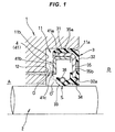
- Fig. 1 is a half sectional view showing a first embodiment of a sealing device in accordance with the present invention by cutting along a plane passing through an axis.
- reference numeral 1 denotes a shaft hole housing of an equipment
- reference numeral 2 denotes a rotating shaft having an approximately horizontal axis and inserted to an inner periphery of the shaft hole housing 1.
- the rotating shaft 2 is rotated around the approximately horizontal axis, and a sealing device main body 3 is installed in a seal installation concave portion 11 formed at an inner periphery of an end portion of the shaft hole housing 1.
- the sealing device main body 3 is integrally formed on a reinforcing ring 35 by a rubber-like elastic material.
- the sealing device main body 3 has an approximately cylindrical attaching portion 31, a radial portion 32 extending to an inner peripheral side from an end portion thereof at an outside space B side, a seal lip 33 extending toward an inside space A side from a waist portion 32a at an inner periphery of the radial portion 32 in such a manner as to form an approximately C-shaped cross section together with the attaching portion 31 and the radial portion 32, a dust lip 34 extending toward an opposite side to the seal lip 33 (the outside space B side) from an inner peripheral end of the waist portion 32a, a metal reinforcing ring 35 embedded over the attaching portion 31 and the radial portion 32, and an extension spring 36 fitted and attached to an outer periphery of the seal lip 33.
- the reinforcing ring 35 is manufactured by press forming of a metal plate, is constituted by a cylinder portion 35a embedded in the attaching portion 31 and an inward collar portion 35b embedded in the radial portion 32, and has an approximately L-shaped cross section.
- the attaching portion 31 is a portion which is pressure inserted and closely fitted to an inner peripheral surface 11a of the seal installation concave portion 11 of the housing 1, and is structured such as to be previously compressed suitably in a radial direction, in the installation state, between the cylinder portion 35a of the reinforcing ring 35 and the inner peripheral surface 11a of the seal installation concave portion 11.
- An inner peripheral portion provided to have an approximately V-shaped cross section in the vicinity of an end of the seal lip 33 is structured such as to be slidably brought into close contact with an outer peripheral surface of the rotating shaft 2 with a suitable fastening margin.
- an inner peripheral edge of the dust lip 34 directed to an opposite side to the seal lip 33 comes close to an outer peripheral surface of the rotating shaft 2 with a minute gap, or is slidably brought into close contact therewith with a slight fastening margin.
- the extension spring 36 is structured by connecting a metal coil spring in an annular shape, is fitted and attached to an annular groove formed in an outer peripheral surface of the seal lip 33, and compensates tension force of the seal lip 33 with respect to an outer peripheral surface of the rotating shaft 2.
- the housing 1 is provided with an oil injection port 12 for injecting oil 0 for lubricating a sliding portion S between an inner peripheral portion of the seal lip 33 and the outer peripheral surface of the rotating shaft 2, for example, so as to be positioned at an upper side of the rotating shaft 2, and the oil injection port 12 is open in a rising surface 11b of the seal installation concave portion 11 of the housing 1, at a radial position to an outer periphery side from the seal lip 33.
- the oil scattering means 4 is attached to the sealing device main body 3.
- the oil scattering means 4 is constructed by a plate 41 manufactured by press forming or the like of a metal plate, and is provided with a pressure insertion tube portion 41a which is pressure inserted and fitted to an inner peripheral surface of the cylinder portion 35a of the reinforcing ring 35 in the sealing device main body 3, and a plate main body portion 41b extending to an inner peripheral side from an end portion thereof at the inside space A side.
- the plate main body portion 41b is positioned slightly to the inside space A side from an end position of the seal lip 33, and an inner peripheral edge 41c thereof is positioned approximately in front of an opening portion of the oil injection port 12.
- the sealing device main body 3 is made so as to prevent an oil to be sealed, for example, in a mist state, existing in the inside space A from leaking to an atmospheric air side of the outside space B from a shaft periphery.
- the dust lip 34 prevents a foreign material in the outside space B from making an intrusion.
- the oil 0 for lubricating the sliding portion S is injected approximately horizontally into the seal installation concave portion 11 from the oil injection port 12 provided in the housing 1 at a pressure about 0.2 MPa. Then, the oil 0 is scattered in a mist state by coming into collision with the inner peripheral edge 41c of the plate main body portion 41b in the plate 41 positioned in front of the oil injection port 12, and a part 0' thereof is scattered toward a front side of the sliding portion S of the seal lip 33.
- the plate main body portion 41b extends to the inner peripheral side from the oil injection port 12
- the oil 0 injected from the oil injection port 12 is rebounded by the plate main body portion 41b completely.
- the part 0' thereof tends to fly to the portion in the vicinity of the sliding portion S of the seal lip 33. Accordingly, it is possible to prevent the rebounded oil 0 from coming into strong collision with the outer peripheral surface of the seal lip 33, and it is possible to urge formation of a good lubricating oil film at the sliding portion S.
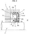
- Fig. 2 is a half sectional view showing a second embodiment of the sealing device in accordance with the present invention by cutting along a plane passing through an axis.
- the sealing device in accordance with the second embodiment is different from the first embodiment mentioned above in the shape of a plate 42 serving as the oil scattering means 4.
- the plate 42 is manufactured by press forming or the like of a metal plate, and is provided with a pressure insertion tube portion 42a pressure inserted and fitted to an inner peripheral surface of the cylinder portion 35a of the reinforcing ring 35 in the sealing device main body 3, a plate main body portion 42b extending to an inner peripheral side along the inward collar portion 35b of the reinforcing ring 35 from an end portion at an opposite side to the inside space A in the pressure insertion tube portion 42a, and a protruding portion 42c bent toward the inside space A side from an inner peripheral end thereof.
- the protruding portion 42c is structured such as to guide the scattering direction of the oil 0 injected from the oil injection port 12 to come into collision with the plate main body portion 42b so as to jump beyond the outer peripheral side of the seal lip 33, and is positioned at an inner periphery side (a lower side) of the colliding position of the oil 0 and an outer peripheral side (an upper side) of the seal lip 33.
- the structures of the other portions such as the sealing device main body 3 and the like are basically the same as those of the first embodiment described above.
- the sealing device main body 3 has the same sealing function as that of the first embodiment. Further, when the oil O for lubricating the sliding portion S of the seal lip 33 is injected into the seal installation concave portion 11 from the oil injection port 12 of the housing 1 at a pressure about 0.2 MPa, the oil 0 becomes in a mist state by coming into collision with an inner peripheral portion of the plate main body portion 42b of the plate 42 at the outer peripheral side (the upper side) of the seal lip 33 so as to be scattered, and the scattering direction is guided so as to jump beyond the outer peripheral side of the seal lip 33 by the protruding portion 42c.
- Fig. 3 is a half sectional view showing a third embodiment of the sealing device in accordance with the present invention by cutting along a plane passing through an axis.
- the sealing device in accordance with the third embodiment is different from the first and second embodiments mentioned above in the shape of a plate 43 serving as the oil scattering means 4.
- the plate 43 is manufactured by press forming or the like of a metal plate, and is provided with a pressure insertion tube portion 43a pressure inserted and fitted to an inner peripheral surface of the cylinder portion 35a of the reinforcing ring 35 in the sealing device main body 3, an intermediate conical tube portion 43b bent from an end portion at the inside space A side of the pressure insertion tube portion 43a so as to become smaller in diameter little by little toward an opposite side to the inside space A, and an inner peripheral conical tube portion 43c bent at the small diameter end portion thereof so as to become smaller in diameter little by little toward the inside space A side.
- the inner peripheral conical tube portion 43c exists at a radial position with which the oil 0 injected from the oil injection port 12 comes into collision, and an angle of incline thereof is set in such a manner that the oil 0 rebounded by the collision comes into collision with the intermediate conical tube portion 43b.
- the structures of the other portions such as the sealing device main body 3 and the like are basically the same as those of the first and second embodiments described above.
- the sealing device main body 3 has the same sealing function as that of the first and second embodiments. Further, when the oil 0 for lubricating the sliding portion S of the seal lip 33 is injected into the seal installation concave portion 11 from the oil injection port 12 provided in the housing 1 at a pressure about 0.2 MPa, the oil 0 is rebounded diagonally toward the outer peripheral side (the upper side) by coming into collision with the inner peripheral conical tube portion 43c of the plate 43 at the outer peripheral side (the upper side) of the seal lip 33, next comes into collision with the intermediate conical tube portion 43b, and is scattered to the inner peripheral side (the lower side) toward the portion in the vicinity of the sliding portion S of the seal lip 33.
- the oil O does not come into strong collision with the outer peripheral surface of the seal lip 33, but is scattered to the portion in the vicinity of the sliding portion S of the seal lip 33, whereby it is possible to urge formation of the good lubricating oil film at this sliding portion S.
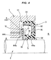
- Fig. 4 is a half sectional view showing a sealing device not according to the invention, by cutting along a plane passing through an axis
- Fig. 5 is a view of a slinger 44 in the fourth example as seen in a direction in parallel to an axis.
- the sealing device in accordance with the fourth example is different from the first to third embodiments mentioned above in a point that the slinger 44 is used as the oil scattering means 4.
- the slinger 44 is manufactured by press punching or the like of a metal plate, and is provided with a sleeve 44a which is pressure inserted and fitted to the outer peripheral surface of the rotating shaft 2, and a slinger main body 44b which expands in a disc shape to an outer peripheral side from an end portion at the inside space A side of in the sleeve 44a, and a plurality of circular holes 44c are provided at in a predetermined interval in a circumferential direction, at radial positions with which the oil 0 injected from the oil injection port 12 of the housing 1 comes into collision, in the slinger main body 44b, as shown in Fig. 5 .
- the inner peripheral portion (the sliding portion S) of the seal lip 33 in the sealing device main body 3 is slidably brought into close contact with the outer peripheral surface of the sleeve 44a of the slinger 44, and an inner peripheral edge of the dust lip 34 comes close to the outer peripheral surface of the sleeve 44a with a minute gap, or is slidably brought into close contact therewith with a slight fastening margin.
- the structures of the other portions such as the sealing device main body 3 and the like are basically the same as those of the first to third embodiments described above.
- the sealing device main body 3 has the same sealing function as that of the first to third embodiments. Further, when the oil 0 for lubricating the sliding portion S of the seal lip 33 is injected into the seal installation concave portion 11 from the oil injection port 12 provided in the housing 1 at the pressure about 0.2 MPa, there are alternately generated the scattering to the front face side caused by the collision of the oil 0 against the slinger main body 44b, and the scattering to the back face side of the slinger main body 44b caused by the pass of the oil 0 through the holes 44c, at the destination of the injection, because the slinger main body 44b of the slinger 44 rotates together with the rotating shaft 2 and the holes 44c provided in the slinger main body 44b pass one after the other in the circumferential direction.
- a passing amount of the oil 0 to the back face side of the slinger main body 44b, at which the seal lip 33 exists, is limited, and the scattering in random directions is generated by interference with inner surfaces of the holes 44c, when the oil 0 passes through the holes 44c moving one after the other in the rotating direction on the basis of the rotation of the slinger 44. Accordingly, a collision pressure of the oil 0 against the outer peripheral surface of the seal lip 33 is diminished, and it is possible to urge formation of a good lubricating oil film at the sliding portion S between the seal lip 33 and the sleeve 44a of the slinger 44.
- the scattering effect with respect to the oil O becomes smaller at that degree.
- the injection pressure of the oil O changes in proportion to a revolutional speed of an engine (a rotating speed of the rotating shaft 2).
- the injection pressure itself of the oil O becomes low at a time of the low speed rotation, no problem is generated even if the oil 0 passing through the holes 44c is rebounded onto the outer peripheral surface of the seal lip 33.
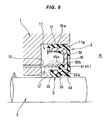
- Fig. 6 is a half sectional view showing a second example of the sealing device not according to the invention by cutting along a plane passing through an axis.
- the sealing device in accordance with the fifth example is different from the first to fourth embodiments/example mentioned above in a point that the oil scattering means 4 is integrally formed in the sealing device main body 3 by a rubber-like elastic material which is provided continuously with the seal lip 33.
- the sealing device main body 3 is basically provided with the same structure as that of each of the embodiments/example mentioned above.
- the sealing device main body 3 has the approximately cylindrical attaching portion 31 which is integrally formed on the metal reinforcing ring 35 by a rubber-like elastic material, the radial portion 32 extending to the inner peripheral side from the end portion at the outside space B side, the seal lip 33 extending toward the inside space A side from the waist portion 32a at the inner periphery of the radial portion 32 in such a manner as to form the approximately C-shaped cross section together with the attaching portion 31 and the radial portion 32, the dust lip 34 extending toward the opposite side (the outside space B side) to the seal lip 33 from the inner peripheral end of the waist portion 32a, a reinforcing ring 35 embedded over the attaching portion 31 and the radial portion 32 and having an approximately L-shaped cross section, and the extension spring 36 fitted and attached to the outer periphery of the seal lip 33.
- An elastic protruding portion 45 which is provided continuously from the seal lip 33 and is made of a rubber-like elastic material is integrally provided as the oil scattering means 4 on a front face side of the inward collar portion 35b of the reinforcing ring 35, and a front face of the elastic protruding portion 45 is formed as an inclined surface 45a directed to an outer peripheral side (an upper side) in such a manner that an axial height of the elastic protruding portion 45 increases toward the inner peripheral side.
- the sealing device main body 3 has the same sealing function as those of the first to fourth embodiments/example. Further, when the oil O for lubricating the sliding portion S of the seal lip 33 is injected into the seal installation concave portion 11 from the oil injection port 12 provided in the housing 1 at the pressure about 0.2 MPa, the oil 0 is rebounded diagonally toward the outer peripheral side (the upper side) by coming into collision with the inclined surface 45a of the elastic protruding portion 45 made of the rubber-like elastic material at the outer peripheral side (the upper side) of the seal lip 33, and is scattered toward the portion in the vicinity of the slide portion S of the seal lip 33. Accordingly, it is possible to urge formation of a good lubricating oil film at the sliding portion S.
- the oil scattering means 4 (the elastic protruding portion 45) is not manufactured as an independent part from the sealing device main body 3 so as to be assembled, like as the first to fourth embodiments/example, but is formed in the sealing device main body 3 by the rubber-like elastic material continuously with the attaching portion 31, the radial portion 32, the seal lip 33 and the dust lip 34, increase of parts number and manufacturing process is not caused.
Landscapes
- Engineering & Computer Science (AREA)
- General Engineering & Computer Science (AREA)
- Mechanical Engineering (AREA)
- Sealing With Elastic Sealing Lips (AREA)
- Sealing Of Bearings (AREA)
Claims (4)
- Dispositif d'étanchéité comprenant :un corps principal de dispositif d'étanchéité (3) ayant une lèvre d'étanchéité (33) qui est mise en contact étroit de façon coulissante avec une surface périphérique extérieure d'un arbre de rotation (2) ; etun port d'injection d'huile (12) pour injecter une huile (0) vers une position à un côté périphérique extérieur de ladite lèvre d'étanchéité (33) dans le corps principal de dispositif d'étanchéité (3),dans lequel le dispositif d'étanchéité est prévu avec un moyen de dispersion d'huile (4) pour faire rebondir l'huile (0) injectée depuis ledit port d'injection d'huile (12) vers une partie à proximité d'une partie coulissante (S) de ladite lèvre d'étanchéité (33) afin de disperser l'huile (0), caractérisé en ce que
le moyen de dispersion d'huile (4) est inséré par pression et fixé à une surface périphérique intérieure d'une partie de cylindre (35a) d'un anneau de renfort (35) dans le corps principal de dispositif d'étanchéité (3). - Dispositif d'étanchéité selon la revendication 1, dans lequel le moyen de dispersion d'huile (4) est constitué par une plaque (41) ayant une partie de corps principal de plaque (41b) qui est positionnée sur le côté port d'injection d'huile (12) de la lèvre d'étanchéité (33), et un bord périphérique intérieur (41c) de la partie de corps principal de plaque (41b) entre en collision avec l'huile (0) injectée depuis le port d'injection d'huile (12) afin de faire rebondir l'huile (0) vers une partie à proximité de la partie coulissante (S) de la lèvre d'étanchéité (33) et la disperser.
- Dispositif d'étanchéité selon la revendication 1, dans lequel le moyen de dispersion d'huile (4) est constitué par une plaque (42) qui est intégralement installée et attachée au corps principal de dispositif d'étanchéité (3), et la plaque (42) a une partie en saillie (42c) pour guider une direction de dispersion causée par la collision de l'huile (0) injectée depuis le port d'injection d'huile (12) d'une manière telle que l'huile saute au-delà du côté périphérique extérieur de la lèvre d'étanchéité (33).
- Dispositif d'étanchéité selon la revendication 1, dans lequel le moyen de dispersion d'huile (4) est constitué par une plaque (43) qui est intégralement installée et attachée au corps principal de dispositif d'étanchéité (3), et la plaque (43) est réalisée en une forme courbée telle de manière à entrer en collision plusieurs fois avec l'huile (0) injectée depuis le port d'injection d'huile (12) pour faire rebondir l'huile (0).
Priority Applications (1)
| Application Number | Priority Date | Filing Date | Title |
|---|---|---|---|
| EP16182921.3A EP3115658B1 (fr) | 2007-02-16 | 2008-01-24 | Dispositif d'obturation |
Applications Claiming Priority (2)
| Application Number | Priority Date | Filing Date | Title |
|---|---|---|---|
| JP2007035914A JP5170365B2 (ja) | 2007-02-16 | 2007-02-16 | 密封装置 |
| PCT/JP2008/050935 WO2008099648A1 (fr) | 2007-02-16 | 2008-01-24 | Dispositif d'étanchéité |
Related Child Applications (1)
| Application Number | Title | Priority Date | Filing Date |
|---|---|---|---|
| EP16182921.3A Division EP3115658B1 (fr) | 2007-02-16 | 2008-01-24 | Dispositif d'obturation |
Publications (3)
| Publication Number | Publication Date |
|---|---|
| EP2119945A1 EP2119945A1 (fr) | 2009-11-18 |
| EP2119945A4 EP2119945A4 (fr) | 2012-12-26 |
| EP2119945B1 true EP2119945B1 (fr) | 2016-08-10 |
Family
ID=39689894
Family Applications (2)
| Application Number | Title | Priority Date | Filing Date |
|---|---|---|---|
| EP08703764.4A Not-in-force EP2119945B1 (fr) | 2007-02-16 | 2008-01-24 | Dispositif d'étanchéité |
| EP16182921.3A Not-in-force EP3115658B1 (fr) | 2007-02-16 | 2008-01-24 | Dispositif d'obturation |
Family Applications After (1)
| Application Number | Title | Priority Date | Filing Date |
|---|---|---|---|
| EP16182921.3A Not-in-force EP3115658B1 (fr) | 2007-02-16 | 2008-01-24 | Dispositif d'obturation |
Country Status (5)
| Country | Link |
|---|---|
| US (1) | US8276917B2 (fr) |
| EP (2) | EP2119945B1 (fr) |
| JP (1) | JP5170365B2 (fr) |
| CN (1) | CN101617154B (fr) |
| WO (1) | WO2008099648A1 (fr) |
Families Citing this family (11)
| Publication number | Priority date | Publication date | Assignee | Title |
|---|---|---|---|---|
| JP5110250B2 (ja) * | 2006-02-06 | 2012-12-26 | Nok株式会社 | オイルシール |
| JP5170365B2 (ja) | 2007-02-16 | 2013-03-27 | Nok株式会社 | 密封装置 |
| JP2009103301A (ja) * | 2007-10-02 | 2009-05-14 | Nok Corp | 密封装置 |
| JP2010270909A (ja) * | 2009-04-24 | 2010-12-02 | Nok Corp | 密封装置 |
| WO2011132337A1 (fr) * | 2010-04-23 | 2011-10-27 | Nok株式会社 | Dispositif d'étanchéité |
| WO2012125992A1 (fr) | 2011-03-17 | 2012-09-20 | Federal-Mogul Corporation | Ensemble joint d'arbre radial à faible couple |
| WO2014034299A1 (fr) * | 2012-08-28 | 2014-03-06 | 日産自動車株式会社 | Dispositif pour l'ajustement par pression d'un joint d'huile |
| JP5964201B2 (ja) | 2012-10-23 | 2016-08-03 | Nok株式会社 | オイルシール |
| WO2014155582A1 (fr) * | 2013-03-27 | 2014-10-02 | 三菱重工業株式会社 | Dispositif de joint d'écubier d'embossage |
| CN107207084B (zh) * | 2016-01-15 | 2018-08-07 | 瓦锡兰日本有限公司 | 船尾管密封系统、船尾管密封装置、船舶及船尾管密封方法 |
| EP3991918A1 (fr) * | 2020-10-28 | 2022-05-04 | Hilti Aktiengesellschaft | Géométrie d'étanchéité pour une machine-outil mobile |
Family Cites Families (33)
| Publication number | Priority date | Publication date | Assignee | Title |
|---|---|---|---|---|
| US1908956A (en) * | 1929-03-15 | 1933-05-16 | Timken Roller Bearing Co | Axle bearing and oil closure |
| US2162486A (en) * | 1937-06-21 | 1939-06-13 | Letourneau Inc | Sealing means for centrifugal pump impellers |
| US2705160A (en) * | 1949-12-27 | 1955-03-29 | Julius E Shafer | Bearing seal |
| US3021161A (en) * | 1959-09-14 | 1962-02-13 | Federal Mogul Bower Bearings | Unitized shaft seal |
| US3682488A (en) * | 1969-09-10 | 1972-08-08 | Nippon Oil Seal Ind Co Ltd | Sealing device |
| JPS5135733Y2 (fr) * | 1971-12-17 | 1976-09-02 | ||
| JPS5346441Y2 (fr) * | 1973-06-19 | 1978-11-07 | ||
| JPS5268055U (fr) * | 1975-11-17 | 1977-05-20 | ||
| JPS5468055U (fr) * | 1977-10-24 | 1979-05-15 | ||
| JPS5468055A (en) | 1977-11-09 | 1979-05-31 | Okada Sangyo Kk | Method of purifying organic sewage |
| JPS5793663U (fr) * | 1980-11-28 | 1982-06-09 | ||
| JPS5793663A (en) * | 1980-11-29 | 1982-06-10 | Fuji Heavy Ind Ltd | Internal combustion engine having plural power sources |
| JPS6016055A (ja) | 1983-07-08 | 1985-01-26 | Nippon Telegr & Teleph Corp <Ntt> | 画像読取り装置 |
| JPS6016055U (ja) * | 1983-07-11 | 1985-02-02 | ヤンマーディーゼル株式会社 | クランク軸用オイルシ−ルの給油構造 |
| JPS61118977A (ja) * | 1984-11-13 | 1986-06-06 | シチズン時計株式会社 | 多電極コネクタ−構造 |
| JPS61118977U (fr) * | 1985-01-09 | 1986-07-26 | ||
| SE453422B (sv) * | 1986-09-15 | 1988-02-01 | Skf Nova Ab | Tetning av axel vid lager eller veggenomgang forsedd med radiellt riktade skovlar |
| DE3638515C1 (de) * | 1986-11-11 | 1988-05-26 | Freudenberg Carl Fa | Kassettendichtung |
| US4808012A (en) * | 1987-03-23 | 1989-02-28 | The Timken Company | Flap seal for anti-friction bearings |
| US4856794A (en) * | 1987-07-23 | 1989-08-15 | Federal-Mogul Corporation | Oil seal with antirotation ribs |
| JPH055340Y2 (fr) * | 1987-11-30 | 1993-02-12 | ||
| JPH0614136Y2 (ja) * | 1988-05-30 | 1994-04-13 | エヌオーケー株式会社 | 密封装置 |
| US5022659A (en) * | 1988-12-27 | 1991-06-11 | The Timken Company | Seal assembly for antifriction bearings |
| DE4124521A1 (de) * | 1991-07-24 | 1993-01-28 | Freudenberg Carl Fa | Kassettendichtung |
| US5718436A (en) * | 1996-07-30 | 1998-02-17 | Dunford; Joseph R. | Flow controller for mechanical seal protection |
| JP3869058B2 (ja) | 1996-12-11 | 2007-01-17 | 株式会社ジェイテクト | オイルシール |
| FR2786547B1 (fr) * | 1998-12-01 | 2001-02-16 | Hutchinson | Joint d'etancheite pour arbre tournant, et dispositif comportant un tel joint |
| JP3754572B2 (ja) * | 1999-04-13 | 2006-03-15 | 本田技研工業株式会社 | 内燃機関におけるオイルシールの潤滑装置 |
| US7931125B2 (en) | 2001-05-16 | 2011-04-26 | Freudenberg-Nok General Partnership | Shaft seal with lubrication device |
| JP4396820B2 (ja) * | 2003-12-26 | 2010-01-13 | Nok株式会社 | オイルシール |
| JP2006046551A (ja) * | 2004-08-06 | 2006-02-16 | Nok Corp | 密封装置 |
| JP5110250B2 (ja) * | 2006-02-06 | 2012-12-26 | Nok株式会社 | オイルシール |
| JP5170365B2 (ja) | 2007-02-16 | 2013-03-27 | Nok株式会社 | 密封装置 |
-
2007
- 2007-02-16 JP JP2007035914A patent/JP5170365B2/ja not_active Expired - Fee Related
-
2008
- 2008-01-24 EP EP08703764.4A patent/EP2119945B1/fr not_active Not-in-force
- 2008-01-24 CN CN2008800052259A patent/CN101617154B/zh not_active Expired - Fee Related
- 2008-01-24 US US12/521,860 patent/US8276917B2/en not_active Expired - Fee Related
- 2008-01-24 WO PCT/JP2008/050935 patent/WO2008099648A1/fr not_active Ceased
- 2008-01-24 EP EP16182921.3A patent/EP3115658B1/fr not_active Not-in-force
Also Published As
| Publication number | Publication date |
|---|---|
| CN101617154A (zh) | 2009-12-30 |
| EP2119945A4 (fr) | 2012-12-26 |
| JP5170365B2 (ja) | 2013-03-27 |
| US8276917B2 (en) | 2012-10-02 |
| JP2008202614A (ja) | 2008-09-04 |
| US20100038863A1 (en) | 2010-02-18 |
| CN101617154B (zh) | 2012-09-05 |
| EP3115658A1 (fr) | 2017-01-11 |
| EP3115658B1 (fr) | 2018-12-05 |
| EP2119945A1 (fr) | 2009-11-18 |
| WO2008099648A1 (fr) | 2008-08-21 |
Similar Documents
| Publication | Publication Date | Title |
|---|---|---|
| EP2119945B1 (fr) | Dispositif d'étanchéité | |
| EP3242054B1 (fr) | Structure d'étanchéité avec un amortisseur de torsion et un joint d'huile | |
| US10544865B2 (en) | Sealing device | |
| EP2881631B1 (fr) | Dispositif d'étanchéité | |
| EP2796754A1 (fr) | Joint d'étanchéité arrière de moteur | |
| CN106133355A (zh) | 滚动轴承 | |
| US20180172077A1 (en) | Sealing device | |
| US20200124178A1 (en) | Sealing apparatus | |
| JP2023017975A (ja) | 密封装置 | |
| CA3110590C (fr) | Bague d`etancheite et utilisation | |
| US12140186B2 (en) | Bearing unit with protection disc | |
| EP3315830B1 (fr) | Ensemble joint d'étanchéité de chemise de cylindre à mouvement alternatif | |
| US11994214B2 (en) | Sealing device | |
| JP6777466B2 (ja) | プーリユニット | |
| EP1816377A1 (fr) | Dispositif d'etancheite | |
| EP3385579B1 (fr) | Dispositif de joint d'étanchéité | |
| US11692591B2 (en) | Sealing device for a bearing unit | |
| JP2018017264A (ja) | シール付き転がり軸受 | |
| JP2009024804A (ja) | 密封装置 | |
| JP2010270909A (ja) | 密封装置 | |
| KR20230040373A (ko) | 휠 베어링용 실링 배열, 및 실링 배열을 포함하는 휠 베어링 유닛 | |
| JP7051310B2 (ja) | 密封装置 | |
| JP2009144823A (ja) | 密封装置 | |
| JP7051311B2 (ja) | 密封装置 | |
| WO2011132337A1 (fr) | Dispositif d'étanchéité |
Legal Events
| Date | Code | Title | Description |
|---|---|---|---|
| PUAI | Public reference made under article 153(3) epc to a published international application that has entered the european phase |
Free format text: ORIGINAL CODE: 0009012 |
|
| 17P | Request for examination filed |
Effective date: 20090701 |
|
| AK | Designated contracting states |
Kind code of ref document: A1 Designated state(s): AT BE BG CH CY CZ DE DK EE ES FI FR GB GR HR HU IE IS IT LI LT LU LV MC MT NL NO PL PT RO SE SI SK TR |
|
| DAX | Request for extension of the european patent (deleted) | ||
| A4 | Supplementary search report drawn up and despatched |
Effective date: 20121128 |
|
| RIC1 | Information provided on ipc code assigned before grant |
Ipc: F16J 15/32 20060101AFI20121122BHEP |
|
| 17Q | First examination report despatched |
Effective date: 20140507 |
|
| GRAP | Despatch of communication of intention to grant a patent |
Free format text: ORIGINAL CODE: EPIDOSNIGR1 |
|
| INTG | Intention to grant announced |
Effective date: 20160217 |
|
| GRAS | Grant fee paid |
Free format text: ORIGINAL CODE: EPIDOSNIGR3 |
|
| GRAA | (expected) grant |
Free format text: ORIGINAL CODE: 0009210 |
|
| AK | Designated contracting states |
Kind code of ref document: B1 Designated state(s): AT BE BG CH CY CZ DE DK EE ES FI FR GB GR HR HU IE IS IT LI LT LU LV MC MT NL NO PL PT RO SE SI SK TR |
|
| REG | Reference to a national code |
Ref country code: GB Ref legal event code: FG4D |
|
| REG | Reference to a national code |
Ref country code: AT Ref legal event code: REF Ref document number: 819359 Country of ref document: AT Kind code of ref document: T Effective date: 20160815 Ref country code: CH Ref legal event code: EP |
|
| REG | Reference to a national code |
Ref country code: IE Ref legal event code: FG4D |
|
| REG | Reference to a national code |
Ref country code: DE Ref legal event code: R096 Ref document number: 602008045531 Country of ref document: DE |
|
| REG | Reference to a national code |
Ref country code: LT Ref legal event code: MG4D |
|
| REG | Reference to a national code |
Ref country code: NL Ref legal event code: MP Effective date: 20160810 |
|
| REG | Reference to a national code |
Ref country code: FR Ref legal event code: PLFP Year of fee payment: 10 |
|
| REG | Reference to a national code |
Ref country code: AT Ref legal event code: MK05 Ref document number: 819359 Country of ref document: AT Kind code of ref document: T Effective date: 20160810 |
|
| PG25 | Lapsed in a contracting state [announced via postgrant information from national office to epo] |
Ref country code: NL Free format text: LAPSE BECAUSE OF FAILURE TO SUBMIT A TRANSLATION OF THE DESCRIPTION OR TO PAY THE FEE WITHIN THE PRESCRIBED TIME-LIMIT Effective date: 20160810 Ref country code: LT Free format text: LAPSE BECAUSE OF FAILURE TO SUBMIT A TRANSLATION OF THE DESCRIPTION OR TO PAY THE FEE WITHIN THE PRESCRIBED TIME-LIMIT Effective date: 20160810 Ref country code: FI Free format text: LAPSE BECAUSE OF FAILURE TO SUBMIT A TRANSLATION OF THE DESCRIPTION OR TO PAY THE FEE WITHIN THE PRESCRIBED TIME-LIMIT Effective date: 20160810 Ref country code: IT Free format text: LAPSE BECAUSE OF FAILURE TO SUBMIT A TRANSLATION OF THE DESCRIPTION OR TO PAY THE FEE WITHIN THE PRESCRIBED TIME-LIMIT Effective date: 20160810 Ref country code: NO Free format text: LAPSE BECAUSE OF FAILURE TO SUBMIT A TRANSLATION OF THE DESCRIPTION OR TO PAY THE FEE WITHIN THE PRESCRIBED TIME-LIMIT Effective date: 20161110 Ref country code: IS Free format text: LAPSE BECAUSE OF FAILURE TO SUBMIT A TRANSLATION OF THE DESCRIPTION OR TO PAY THE FEE WITHIN THE PRESCRIBED TIME-LIMIT Effective date: 20161210 Ref country code: HR Free format text: LAPSE BECAUSE OF FAILURE TO SUBMIT A TRANSLATION OF THE DESCRIPTION OR TO PAY THE FEE WITHIN THE PRESCRIBED TIME-LIMIT Effective date: 20160810 |
|
| PG25 | Lapsed in a contracting state [announced via postgrant information from national office to epo] |
Ref country code: GR Free format text: LAPSE BECAUSE OF FAILURE TO SUBMIT A TRANSLATION OF THE DESCRIPTION OR TO PAY THE FEE WITHIN THE PRESCRIBED TIME-LIMIT Effective date: 20161111 Ref country code: PL Free format text: LAPSE BECAUSE OF FAILURE TO SUBMIT A TRANSLATION OF THE DESCRIPTION OR TO PAY THE FEE WITHIN THE PRESCRIBED TIME-LIMIT Effective date: 20160810 Ref country code: ES Free format text: LAPSE BECAUSE OF FAILURE TO SUBMIT A TRANSLATION OF THE DESCRIPTION OR TO PAY THE FEE WITHIN THE PRESCRIBED TIME-LIMIT Effective date: 20160810 Ref country code: SE Free format text: LAPSE BECAUSE OF FAILURE TO SUBMIT A TRANSLATION OF THE DESCRIPTION OR TO PAY THE FEE WITHIN THE PRESCRIBED TIME-LIMIT Effective date: 20160810 Ref country code: AT Free format text: LAPSE BECAUSE OF FAILURE TO SUBMIT A TRANSLATION OF THE DESCRIPTION OR TO PAY THE FEE WITHIN THE PRESCRIBED TIME-LIMIT Effective date: 20160810 Ref country code: LV Free format text: LAPSE BECAUSE OF FAILURE TO SUBMIT A TRANSLATION OF THE DESCRIPTION OR TO PAY THE FEE WITHIN THE PRESCRIBED TIME-LIMIT Effective date: 20160810 Ref country code: PT Free format text: LAPSE BECAUSE OF FAILURE TO SUBMIT A TRANSLATION OF THE DESCRIPTION OR TO PAY THE FEE WITHIN THE PRESCRIBED TIME-LIMIT Effective date: 20161212 |
|
| PG25 | Lapsed in a contracting state [announced via postgrant information from national office to epo] |
Ref country code: EE Free format text: LAPSE BECAUSE OF FAILURE TO SUBMIT A TRANSLATION OF THE DESCRIPTION OR TO PAY THE FEE WITHIN THE PRESCRIBED TIME-LIMIT Effective date: 20160810 Ref country code: RO Free format text: LAPSE BECAUSE OF FAILURE TO SUBMIT A TRANSLATION OF THE DESCRIPTION OR TO PAY THE FEE WITHIN THE PRESCRIBED TIME-LIMIT Effective date: 20160810 |
|
| REG | Reference to a national code |
Ref country code: DE Ref legal event code: R097 Ref document number: 602008045531 Country of ref document: DE |
|
| PG25 | Lapsed in a contracting state [announced via postgrant information from national office to epo] |
Ref country code: SK Free format text: LAPSE BECAUSE OF FAILURE TO SUBMIT A TRANSLATION OF THE DESCRIPTION OR TO PAY THE FEE WITHIN THE PRESCRIBED TIME-LIMIT Effective date: 20160810 Ref country code: DK Free format text: LAPSE BECAUSE OF FAILURE TO SUBMIT A TRANSLATION OF THE DESCRIPTION OR TO PAY THE FEE WITHIN THE PRESCRIBED TIME-LIMIT Effective date: 20160810 Ref country code: BE Free format text: LAPSE BECAUSE OF FAILURE TO SUBMIT A TRANSLATION OF THE DESCRIPTION OR TO PAY THE FEE WITHIN THE PRESCRIBED TIME-LIMIT Effective date: 20160810 Ref country code: CZ Free format text: LAPSE BECAUSE OF FAILURE TO SUBMIT A TRANSLATION OF THE DESCRIPTION OR TO PAY THE FEE WITHIN THE PRESCRIBED TIME-LIMIT Effective date: 20160810 Ref country code: BG Free format text: LAPSE BECAUSE OF FAILURE TO SUBMIT A TRANSLATION OF THE DESCRIPTION OR TO PAY THE FEE WITHIN THE PRESCRIBED TIME-LIMIT Effective date: 20161110 |
|
| PLBE | No opposition filed within time limit |
Free format text: ORIGINAL CODE: 0009261 |
|
| STAA | Information on the status of an ep patent application or granted ep patent |
Free format text: STATUS: NO OPPOSITION FILED WITHIN TIME LIMIT |
|
| 26N | No opposition filed |
Effective date: 20170511 |
|
| PG25 | Lapsed in a contracting state [announced via postgrant information from national office to epo] |
Ref country code: SI Free format text: LAPSE BECAUSE OF FAILURE TO SUBMIT A TRANSLATION OF THE DESCRIPTION OR TO PAY THE FEE WITHIN THE PRESCRIBED TIME-LIMIT Effective date: 20160810 |
|
| REG | Reference to a national code |
Ref country code: CH Ref legal event code: PL |
|
| PG25 | Lapsed in a contracting state [announced via postgrant information from national office to epo] |
Ref country code: MC Free format text: LAPSE BECAUSE OF FAILURE TO SUBMIT A TRANSLATION OF THE DESCRIPTION OR TO PAY THE FEE WITHIN THE PRESCRIBED TIME-LIMIT Effective date: 20160810 |
|
| PG25 | Lapsed in a contracting state [announced via postgrant information from national office to epo] |
Ref country code: LI Free format text: LAPSE BECAUSE OF NON-PAYMENT OF DUE FEES Effective date: 20170131 Ref country code: CH Free format text: LAPSE BECAUSE OF NON-PAYMENT OF DUE FEES Effective date: 20170131 |
|
| REG | Reference to a national code |
Ref country code: IE Ref legal event code: MM4A |
|
| PG25 | Lapsed in a contracting state [announced via postgrant information from national office to epo] |
Ref country code: LU Free format text: LAPSE BECAUSE OF NON-PAYMENT OF DUE FEES Effective date: 20170124 |
|
| REG | Reference to a national code |
Ref country code: FR Ref legal event code: PLFP Year of fee payment: 11 |
|
| PG25 | Lapsed in a contracting state [announced via postgrant information from national office to epo] |
Ref country code: IE Free format text: LAPSE BECAUSE OF NON-PAYMENT OF DUE FEES Effective date: 20170124 |
|
| PG25 | Lapsed in a contracting state [announced via postgrant information from national office to epo] |
Ref country code: MT Free format text: LAPSE BECAUSE OF NON-PAYMENT OF DUE FEES Effective date: 20170124 |
|
| PG25 | Lapsed in a contracting state [announced via postgrant information from national office to epo] |
Ref country code: HU Free format text: LAPSE BECAUSE OF FAILURE TO SUBMIT A TRANSLATION OF THE DESCRIPTION OR TO PAY THE FEE WITHIN THE PRESCRIBED TIME-LIMIT; INVALID AB INITIO Effective date: 20080124 |
|
| PG25 | Lapsed in a contracting state [announced via postgrant information from national office to epo] |
Ref country code: CY Free format text: LAPSE BECAUSE OF NON-PAYMENT OF DUE FEES Effective date: 20160810 |
|
| PGFP | Annual fee paid to national office [announced via postgrant information from national office to epo] |
Ref country code: FR Payment date: 20191216 Year of fee payment: 13 |
|
| PG25 | Lapsed in a contracting state [announced via postgrant information from national office to epo] |
Ref country code: TR Free format text: LAPSE BECAUSE OF FAILURE TO SUBMIT A TRANSLATION OF THE DESCRIPTION OR TO PAY THE FEE WITHIN THE PRESCRIBED TIME-LIMIT Effective date: 20160810 |
|
| PGFP | Annual fee paid to national office [announced via postgrant information from national office to epo] |
Ref country code: DE Payment date: 20200114 Year of fee payment: 13 Ref country code: GB Payment date: 20200115 Year of fee payment: 13 |
|
| REG | Reference to a national code |
Ref country code: DE Ref legal event code: R119 Ref document number: 602008045531 Country of ref document: DE |
|
| GBPC | Gb: european patent ceased through non-payment of renewal fee |
Effective date: 20210124 |
|
| PG25 | Lapsed in a contracting state [announced via postgrant information from national office to epo] |
Ref country code: FR Free format text: LAPSE BECAUSE OF NON-PAYMENT OF DUE FEES Effective date: 20210131 |
|
| PG25 | Lapsed in a contracting state [announced via postgrant information from national office to epo] |
Ref country code: DE Free format text: LAPSE BECAUSE OF NON-PAYMENT OF DUE FEES Effective date: 20210803 Ref country code: GB Free format text: LAPSE BECAUSE OF NON-PAYMENT OF DUE FEES Effective date: 20210124 |