EP2796754A1 - Joint d'étanchéité arrière de moteur - Google Patents
Joint d'étanchéité arrière de moteur Download PDFInfo
- Publication number
- EP2796754A1 EP2796754A1 EP12859542.8A EP12859542A EP2796754A1 EP 2796754 A1 EP2796754 A1 EP 2796754A1 EP 12859542 A EP12859542 A EP 12859542A EP 2796754 A1 EP2796754 A1 EP 2796754A1
- Authority
- EP
- European Patent Office
- Prior art keywords
- seal
- lip
- end plate
- exterior side
- muddy water
- Prior art date
- Legal status (The legal status is an assumption and is not a legal conclusion. Google has not performed a legal analysis and makes no representation as to the accuracy of the status listed.)
- Granted
Links
Images

Classifications
-
- F—MECHANICAL ENGINEERING; LIGHTING; HEATING; WEAPONS; BLASTING
- F16—ENGINEERING ELEMENTS AND UNITS; GENERAL MEASURES FOR PRODUCING AND MAINTAINING EFFECTIVE FUNCTIONING OF MACHINES OR INSTALLATIONS; THERMAL INSULATION IN GENERAL
- F16J—PISTONS; CYLINDERS; SEALINGS
- F16J15/00—Sealings
- F16J15/16—Sealings between relatively-moving surfaces
- F16J15/32—Sealings between relatively-moving surfaces with elastic sealings, e.g. O-rings
- F16J15/3204—Sealings between relatively-moving surfaces with elastic sealings, e.g. O-rings with at least one lip
-
- F—MECHANICAL ENGINEERING; LIGHTING; HEATING; WEAPONS; BLASTING
- F02—COMBUSTION ENGINES; HOT-GAS OR COMBUSTION-PRODUCT ENGINE PLANTS
- F02F—CYLINDERS, PISTONS OR CASINGS, FOR COMBUSTION ENGINES; ARRANGEMENTS OF SEALINGS IN COMBUSTION ENGINES
- F02F11/00—Arrangements of sealings in combustion engines
-
- F—MECHANICAL ENGINEERING; LIGHTING; HEATING; WEAPONS; BLASTING
- F02—COMBUSTION ENGINES; HOT-GAS OR COMBUSTION-PRODUCT ENGINE PLANTS
- F02F—CYLINDERS, PISTONS OR CASINGS, FOR COMBUSTION ENGINES; ARRANGEMENTS OF SEALINGS IN COMBUSTION ENGINES
- F02F11/00—Arrangements of sealings in combustion engines
- F02F11/007—Arrangements of sealings in combustion engines involving rotary applications
-
- F—MECHANICAL ENGINEERING; LIGHTING; HEATING; WEAPONS; BLASTING
- F02—COMBUSTION ENGINES; HOT-GAS OR COMBUSTION-PRODUCT ENGINE PLANTS
- F02F—CYLINDERS, PISTONS OR CASINGS, FOR COMBUSTION ENGINES; ARRANGEMENTS OF SEALINGS IN COMBUSTION ENGINES
- F02F7/00—Casings, e.g. crankcases
-
- F—MECHANICAL ENGINEERING; LIGHTING; HEATING; WEAPONS; BLASTING
- F16—ENGINEERING ELEMENTS AND UNITS; GENERAL MEASURES FOR PRODUCING AND MAINTAINING EFFECTIVE FUNCTIONING OF MACHINES OR INSTALLATIONS; THERMAL INSULATION IN GENERAL
- F16J—PISTONS; CYLINDERS; SEALINGS
- F16J15/00—Sealings
- F16J15/16—Sealings between relatively-moving surfaces
- F16J15/164—Sealings between relatively-moving surfaces the sealing action depending on movements; pressure difference, temperature or presence of leaking fluid
-
- F—MECHANICAL ENGINEERING; LIGHTING; HEATING; WEAPONS; BLASTING
- F16—ENGINEERING ELEMENTS AND UNITS; GENERAL MEASURES FOR PRODUCING AND MAINTAINING EFFECTIVE FUNCTIONING OF MACHINES OR INSTALLATIONS; THERMAL INSULATION IN GENERAL
- F16J—PISTONS; CYLINDERS; SEALINGS
- F16J15/00—Sealings
- F16J15/16—Sealings between relatively-moving surfaces
- F16J15/32—Sealings between relatively-moving surfaces with elastic sealings, e.g. O-rings
- F16J15/3204—Sealings between relatively-moving surfaces with elastic sealings, e.g. O-rings with at least one lip
- F16J15/3232—Sealings between relatively-moving surfaces with elastic sealings, e.g. O-rings with at least one lip having two or more lips
-
- F—MECHANICAL ENGINEERING; LIGHTING; HEATING; WEAPONS; BLASTING
- F16—ENGINEERING ELEMENTS AND UNITS; GENERAL MEASURES FOR PRODUCING AND MAINTAINING EFFECTIVE FUNCTIONING OF MACHINES OR INSTALLATIONS; THERMAL INSULATION IN GENERAL
- F16J—PISTONS; CYLINDERS; SEALINGS
- F16J15/00—Sealings
- F16J15/16—Sealings between relatively-moving surfaces
- F16J15/32—Sealings between relatively-moving surfaces with elastic sealings, e.g. O-rings
- F16J15/3244—Sealings between relatively-moving surfaces with elastic sealings, e.g. O-rings with hydrodynamic pumping action
-
- F—MECHANICAL ENGINEERING; LIGHTING; HEATING; WEAPONS; BLASTING
- F16—ENGINEERING ELEMENTS AND UNITS; GENERAL MEASURES FOR PRODUCING AND MAINTAINING EFFECTIVE FUNCTIONING OF MACHINES OR INSTALLATIONS; THERMAL INSULATION IN GENERAL
- F16J—PISTONS; CYLINDERS; SEALINGS
- F16J15/00—Sealings
- F16J15/16—Sealings between relatively-moving surfaces
- F16J15/32—Sealings between relatively-moving surfaces with elastic sealings, e.g. O-rings
- F16J15/3248—Sealings between relatively-moving surfaces with elastic sealings, e.g. O-rings provided with casings or supports
- F16J15/3252—Sealings between relatively-moving surfaces with elastic sealings, e.g. O-rings provided with casings or supports with rigid casings or supports
- F16J15/3256—Sealings between relatively-moving surfaces with elastic sealings, e.g. O-rings provided with casings or supports with rigid casings or supports comprising two casing or support elements, one attached to each surface, e.g. cartridge or cassette seals
- F16J15/3264—Sealings between relatively-moving surfaces with elastic sealings, e.g. O-rings provided with casings or supports with rigid casings or supports comprising two casing or support elements, one attached to each surface, e.g. cartridge or cassette seals the elements being separable from each other
Definitions
- the present invention relates to an engine rear seal which is used for inhibiting muddy water from entering as well as sealing an engine oil in a rear end portion of a crank shaft in an engine for a vehicle such as a motor vehicle.
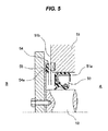
- FIG. 5 An engine rear seal which has been previously proposed by the applicant of the present invention and is shown in Fig. 5 is structured such that a non-contact type dust seal 54 is provided in a motor exterior side B of an oil seal 53 which is installed to an inner periphery of a shaft hole 51 a of a housing 51 and slidably comes into close contact with a peripheral surface of a shaft 52, the non-contact type dust seal 54 being constructed by a combination of a magnetic encoder 55 and a housing end surface 51 b, and the engine rear seal is a double seal structure which is constructed by the dust seal 54 and the oil seal 53. Therefore, it is possible to achieve an excellent sealing performance.
- the non-contact type seal 54 is structured such as to be provided in the motor exterior side B of the oil seal 53, muddy water in the motor exterior side B enters through a gap portion 54a of the non-contact type seal 54. With reference to the muddy water entrance, it is demanded to further improve a sealing performance against the muddy water (a muddy water sealing performance).
- Patent Document 1 Japanese Unexamined Patent Publication No. 2006-46097
- the present invention is made by taking the above point into consideration, and an object of the present invention is to provided an engine rear seal which can further improve a muddy water sealing performance, and can inhibit rotary torque from being increased.
- an engine rear seal is an engine rear seal installed to an engine rear portion in which an end plate is arranged in a motor exterior side of a housing, and a flywheel connected to a shaft is arranged in further a motor exterior side of the end plate, wherein the engine rear seal has an oil seal which is installed to an inner periphery of a shaft hole of the housing and slidably comes into close contact with a peripheral surface of the shaft, and a muddy water preventing seal which is arranged in a motor exterior side of the oil seal, the muddy water preventing seal integrally has an attaching portion which is attached onto the peripheral surface of the shaft, and a seal lip which is provided so as to be directed to an outer side in a diametrical direction from the attaching portion and slidably comes into close contact with an end surface in the motor exterior side of the end plate, the seal lip has a lip end back surface portion which is formed into an inclined surface shape so that an outer diameter becomes smaller according to moving
- an engine rear seal according to a second aspect of the present invention is the engine rear seal described in the first aspect mentioned above, wherein the muddy water preventing seal is attached onto a peripheral surface of the shaft in an inner peripheral side of the end plate in which a gap in an axial direction between the muddy water preventing seal and the flywheel is set to be equal to or less than 3 mm.
- the muddy water preventing seal is combined with the oil seal, and the muddy water preventing seal integrally has the attaching portion which is attached onto the peripheral surface of the shaft, and the seal lip which is provided so as to be directed to the outer side in the diametrical direction from the attaching portion and slidably comes into close contact with the end surface in the motor exterior side of the end plate, that is, the muddy water preventing seal is constructed as the contact type seal.
- the contact type seal is structured such that any gap is not formed in the case that the seal lip is in contact with the other member (the end plate), and is accordingly excellent in the sealing performance in comparison with the non-contact type seal which forms a gap.
- the seal lip has the lip end back surface portion which is formed into the inclined surface shape so that the outer diameter becomes smaller according to the moving far away from the end surface in the motor exterior side of the end plate.
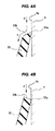
- the seal lip has the lip end back surface portion which is formed into a scraper shape. Since the muddy water (an arrow d) entering from the above side of the seal lip 33 flows in a direction in which the muddy water moves away from the end plate 4 according to the incline of the inclined surface on the lip end back surface portion 33b (an arrow e) as shown in Fig.
- Fig. 4B which is shown as a comparative example, the direction of incline of the lip end back surface portion 33b is inverted, that is, the seal lip is formed into the inclined surface shape so that the outer diameter becomes larger according to the movement of the lip end back surface portion 33b away from the end plate 4. Therefore, the muddy water (an arrow d) entering from the above side of the seal lip 33 stays on the lip end back surface 33b, or flows in a circumferential direction from the lip end back surface. In any case, it is highly likely that the muddy water enters into the inside space of the seal lip 33 from the sliding portion where the lip end 33a comes into contact with the end plate 4.
- the seal lip is structured such that the lip end comes into contact with the end surface in the motor exterior side of the end plate when the shaft rotates at the low speed, and the lip end moves away from the end surface in the motor exterior side of the end plate on the basis of the action of the centrifugal force when the shaft rotates at the high speed.
- the lip end moves away from the end surface in the motor exterior side of the end plate on the basis of the action of the centrifugal force at the high speed rotating time of the shaft having the great sliding torque, it is possible to inhibit the sliding torque from being extremely increased.
- the vehicle such as the motor vehicle is expected to travel at the low speed.
- the shaft rotates at the low speed and the lip end is in contact with the end surface in the motor exterior side of the end plate, it is thought that the shortfall of the muddy water sealing performance is not generated.
- the engine rear seal according to the present invention is used under a condition that the end plate is arranged in the motor exterior side of the housing and the flywheel connected to the shaft is arranged further in the motor exterior side of the end plate, as mentioned above, it is thought that the muddy water sealing performance is further improved by setting the non-contact type seal formed by a small gap in an axial direction between the end plate and the flywheel.
- the magnitude of the gap is preferably equal to or less than 3 mm. In this case, since the gap is narrow, the muddy water preventing seal can be attached onto the peripheral surface of the shaft in the inner peripheral side of the end plate.
- the present invention achieves the following effects.
- the muddy water preventing seal is combined with the oil seal, and the muddy water preventing seal is constructed as the contact type seal integrally having the attaching portion which is attached onto the peripheral surface of the shaft, and the seal lip which is provided from the attaching portion toward the outer side in the diametrical direction and slidably comes into close contact with the end surface in the motor exterior side of the end plate, under the condition that the end plate is arranged in the motor exterior side of the housing, and the flywheel connected to the shaft is arranged further in the motor exterior side of the end plate. Therefore, it is possible to improve the muddy water sealing performance.
- the lip end back surface portion is formed into the scraper shape, and flows the entering muddy water in the direction in which the muddy water moves away from the lip sliding portion, it is possible to further improve the muddy water sealing performance.
- the non-contact type third seal is set between the end plate and the flywheel, in addition to the oil seal and the muddy water preventing seal. Therefore, it is possible to further improve the muddy water sealing performance.
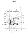
- Fig. 1 shows a half cut cross section of an engine rear seal (a sealing device) 1 according to an embodiment of the present invention.
- Fig. 2 shows a single part state of an oil seal 11 which is used in the engine rear seal 1.
- the engine rear seal 1 according to the embodiment is used for sealing an engine oil in a motor interior side (a sealing fluid side) A in a rear end portion of a crank shaft 2 in an engine for a vehicle such as a motor vehicle, and for inhibiting muddy water from entering in a motor exterior side (an atmospheric air side) B.
- an end plate 4 is arranged in the motor exterior side B of a housing (an engine housing) 3, and a flywheel 5 connected to the shaft 2 is arranged further in the motor exterior side B of the end plate 4.
- the end plate 4 is drawn by a virtual line.
- the engine rear seal 1 has an oil seal 11 which is installed to an inner periphery of a shaft hole 3a of the housing 3 and slidably comes into close contact with a peripheral surface of the shaft 2, and a muddy water preventing seal 31 which is arranged in the motor exterior side B of the oil seal 11.
- the muddy water preventing seal 31 integrally has an attaching portion 32 which is attached onto a peripheral surface of the shaft 2, and a seal lip 33 which is provided from the attaching portion 32 toward an outer side in a diametrical direction and slidably comes into close contact with an end surface 4a in the motor exterior side of the end plate 4.
- the seal lip 33 has a lip end 33a, and also has a lip end back surface portion 33b which is formed into an inclined surface shape so that an outer diameter becomes smaller little by little according to moving far away from the end surface 4a in the motor exterior side of the end plate 4. Further, the seal lip 33 is structured such that the lip end 33a comes into contact with the end surface 4a in the motor exterior side of the end plate 4 when the shaft 2 rotates at a low speed, and the lip end 33a moves away from the end surface 4a in the motor exterior side of the end plate 4 on the basis of an action of a centrifugal force when the shaft 2 rotates at a high speed, so that the lip end 33a is movable close to and away from the end surface 4a.
- the oil seal 11 is formed into an annular shape by a predetermined rubber-like elastic body (FKM which is excellent in a heat resistance), and integrally has an attaching portion 12 which is attached to an inner peripheral surface of a shaft hole 3a of the housing 3, a flange portion 13 which is provided from an end portion in a motor exterior side of the attaching portion 12 toward an inner side in a diametrical direction, and a seal portion 14 which is provided in an inner peripheral end portion of the flange portion 13, as its constituting elements, and the seal portion 14 is integrally provided with a seal lip (a first radial lip) 15 which is directed to the motor interior side A and slidably comes into close contact with a peripheral surface of the shaft 2, a first dust lip (a second radial lip) 16 which is directed to the motor exterior side B and slidably comes into close contact with the peripheral surface of the shaft 2, and a second dust lip (a side lip) 17 which is directed to the motor exterior side B in the same manner and slidably comes into close contact with the
- a metal ring 18 approximately formed into an L-shaped cross sectional form is embedded in the attaching portion 12 and the flange portion 13.
- a garter spring 19 is fitted to the seal lip 15.
- a projection 20 for constructing a screw seal is provided in an inner peripheral surface of the seal lip 15, that is, an inclined surface in the motor exterior side, and a projection 21 for controlling a contact attitude of the lip 16 is provided in an inner peripheral surface of the first dust lip (the second radial lip) 16.
- the muddy water preventing seal 31 is formed into an annular shape by a predetermined rubber-like elastic body (FKM which is excellent in the heat resistance or HNBR which is excellent in a muddy water resistance), and integrally has an attaching portion 32 which is attached onto the peripheral surface of the shaft 2, and a seal lip 33 which is provided form an end portion in the motor exterior side of the attaching portion 32 toward an outer side in a diametrical direction and slidably comes into close contact with the end surface 4a in the motor exterior side of the end plate 4, as its constituting elements.
- a metal ring 34 is embedded in the attaching portion 32.
- the seal lip 33 is formed diagonally outward so that its leading end portion is positioned closer to the motor interior side A than its base end portion, and slidably comes into close contact with the end surface 4a in the motor exterior side of the end plate 4 by the lip end 33a corresponding to its leading end portion.
- the seal lip 33 has three surfaces which are constructed by a motor interior side end surface 33c, a motor exterior side end surface 33d and a leading end surface 33e.
- the motor interior side end surface 33c is provided diagonally outward so that its leading end portion is positioned closer to the motor interior side A than its base end portion so as to form an inclined surface.
- the motor exterior side end surface 33d is also provided diagonally outward so that its leading end portion is positioned closer to the motor interior side A than its base end portion so as to form an inclined surface.
- the leading end surface 33e forms an inclined surface so that an outer diameter becomes smaller little by little from the leading end portion of the motor interior side end surface 33a toward the leading end portion of the motor exterior side end surface 33d.
- the lip end 33a is formed at a position where the motor interior side end surface 33c and the leading end surface 33e intersect.
- the lip end back surface portion 33b is formed by the leading end surface 33e.
- the seal lip 33 is structured, as mentioned above, such that the lip end 33a comes into contact with the end surface 4a in the motor exterior side of the end plate 4 when the shaft 2 rotates at a low speed, and the lip end 33a swings in a direction of an arrow f and moves away from the end surface 4a in the motor exterior side of the end plate 4 on the basis of the action of the centrifugal force when the shaft 2 rotates at a high speed.
- the muddy water preventing seal 31 including the seal lip 33 is structured such as to be attached onto the peripheral surface of the shaft 2 in the inner peripheral side of the end plate 4 in which an axial gap c between the muddy water preventing seal 31 and the flywheel 5 is set to be equal to or less than 3 mm (0 ⁇ c ⁇ 3 mm).
- the muddy water preventing seal 31 is combined with the motor exterior side B of the oil seal 11, and the muddy water preventing seal 31 integrally has the attaching portion 32 which is attached onto the peripheral surface of the shaft 2, and the seal lip 33 which is provided so as to be directed to the outer side in the diametrical direction from the attaching portion 32 and slidably comes into close contact with the end surface 4a in the motor exterior side of the end plate 4, that is, the muddy water preventing seal is constructed as the contact type seal.
- the contact type seal is structured such that any gap is not formed in the case that the seal lip 33 is in contact with the other member (the end plate 4), and is accordingly excellent in the sealing performance in comparison with the non-contact type seal which forms a gap. Therefore, according to the embodiment of the present invention, it is possible to improve the muddy water sealing performance.
- the seal lip 33 has the lip end back surface portion 33b which is formed into the inclined surface shape so that the outer diameter becomes smaller according to the moving far away from the end surface 4a in the motor exterior side of the end plate 4.
- the seal lip 33 has the lip end back surface portion 33b which is formed into a scraper shape. Since the muddy water (the arrow d) entering from the above side of the seal lip 33 flows in a direction in which the muddy water moves away from the end plate 4 according to the incline of the inclined surface on the lip end back surface portion 33b (an arrow e) as shown in Fig.
- Fig. 4B which is shown as a comparative example, the direction of incline of the lip end back surface portion 33b is inverted, that is, the seal lip is formed into the inclined surface shape so that the outer diameter becomes larger little by little according to the movement of the lip end back surface portion 33b away from end surface 4a in the motor external side of the end plate 4.
- the muddy water (an arrow d) entering from the above side of the seal lip 33 stays on the lip end back surface 33b, or flows in a circumferential direction from the lip end back surface.
- the seal lip 33 is structured such that the lip end 33a comes into contact with the end surface 4a in the motor exterior side of the end plate 4 when the shaft 2 rotates at the low speed, and the lip end 33a moves away from the end surface 4a in the motor exterior side of the end plate 4 on the basis of the action of the centrifugal force when the shaft 2 rotates at the high speed. Therefore, since the lip end 33a moves away from the end surface 4a in the motor exterior side of the end plate 4 on the basis of the action of the centrifugal force at the high-speed rotating time of the shaft 2 having the great sliding torque, it is possible to inhibit the sliding torque from being extremely increased.
- the muddy water preventing seal 31 is structured such as to be attached onto the peripheral surface of the shaft 2 in the inner peripheral side of the end plate 4 in which the axial gap c between the muddy water preventing seal 31 and the flywheel 5 is set to be equal to or less than 3 mm. Therefore, since the non-contact type third seal is set between the end plate 4 and the flywheel 5, in addition to the oil seal 11 and the muddy water preventing seal 31, it is possible to further improve the muddy water sealing performance.
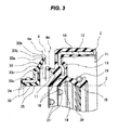
- the muddy water preventing seal 31 is structured such that the seal lip 33 is integrally formed in the end portion in the motor exterior side of the attaching portion 32, however, the seal lip 33 may be integrally formed in the end portion in the motor interior side of the attaching portion as shown in Fig. 3 for certain reasons of an installing space.
- the muddy water preventing seal 31 is metal fitted to the shaft 2 by the metal ring 34, however, may be rubber fitted to the shaft 2 by attaching a rubber portion 35 which is integrally formed with the seal lip 33 to an inner peripheral surface of the metal ring 34 as shown in Fig. 3 .
- a plurality of (two) first dust lips (second radial lips) 16 are provided in the oil seal 11 in Fig. 3 .
Landscapes
- Engineering & Computer Science (AREA)
- General Engineering & Computer Science (AREA)
- Mechanical Engineering (AREA)
- Chemical & Material Sciences (AREA)
- Combustion & Propulsion (AREA)
- Physics & Mathematics (AREA)
- Fluid Mechanics (AREA)
- Sealing With Elastic Sealing Lips (AREA)
Applications Claiming Priority (2)
| Application Number | Priority Date | Filing Date | Title |
|---|---|---|---|
| JP2011279433A JP5800148B2 (ja) | 2011-12-21 | 2011-12-21 | エンジンリアシール |
| PCT/JP2012/071539 WO2013094251A1 (fr) | 2011-12-21 | 2012-08-27 | Joint d'étanchéité arrière de moteur |
Publications (3)
| Publication Number | Publication Date |
|---|---|
| EP2796754A1 true EP2796754A1 (fr) | 2014-10-29 |
| EP2796754A4 EP2796754A4 (fr) | 2015-07-22 |
| EP2796754B1 EP2796754B1 (fr) | 2017-06-07 |
Family
ID=48668158
Family Applications (1)
| Application Number | Title | Priority Date | Filing Date |
|---|---|---|---|
| EP12859542.8A Active EP2796754B1 (fr) | 2011-12-21 | 2012-08-27 | Joint d'étanchéité arrière de moteur |
Country Status (6)
| Country | Link |
|---|---|
| US (1) | US9638329B2 (fr) |
| EP (1) | EP2796754B1 (fr) |
| JP (1) | JP5800148B2 (fr) |
| KR (1) | KR101902430B1 (fr) |
| CN (1) | CN103998836B (fr) |
| WO (1) | WO2013094251A1 (fr) |
Cited By (2)
| Publication number | Priority date | Publication date | Assignee | Title |
|---|---|---|---|---|
| FR3029982A1 (fr) * | 2014-12-11 | 2016-06-17 | Snecma | Joint asservi a etancheite double, axiale et radiale |
| CN105736705A (zh) * | 2016-05-05 | 2016-07-06 | 青岛开世密封工业有限公司 | 一种大马力发动机曲轴ptfe组合油封 |
Families Citing this family (13)
| Publication number | Priority date | Publication date | Assignee | Title |
|---|---|---|---|---|
| WO2015186677A1 (fr) * | 2014-06-03 | 2015-12-10 | Nok株式会社 | Dispositif d'étanchéité |
| JP6366003B2 (ja) * | 2014-07-01 | 2018-08-01 | Nok株式会社 | 密封装置 |
| KR101873175B1 (ko) * | 2014-08-20 | 2018-06-29 | 엔오케이 가부시키가이샤 | 밀봉구조 |
| KR101889241B1 (ko) * | 2014-11-18 | 2018-08-16 | 엔오케이 가부시키가이샤 | 밀봉구조 |
| EP3222893B1 (fr) * | 2014-12-04 | 2019-10-16 | Nok Corporation | Structure d'étanchéité avec un amortisseur à torsion et un joint d'étanchéité à huile |
| US10330202B2 (en) * | 2015-03-18 | 2019-06-25 | Nok Corporation | Sealing device |
| JP6830060B2 (ja) * | 2015-05-11 | 2021-02-17 | Nok株式会社 | 密封装置 |
| CN108138964A (zh) * | 2015-11-24 | 2018-06-08 | Nok株式会社 | 密封装置 |
| SE542479C2 (en) * | 2016-11-28 | 2020-05-19 | Scania Cv Ab | A combustion engine comprising a sealing arrangement for a rotatable shaft |
| US11781653B2 (en) * | 2018-07-09 | 2023-10-10 | Nok Corporation | Sealing device |
| JP7475453B2 (ja) * | 2020-07-27 | 2024-04-26 | Nok株式会社 | 密封装置 |
| CN113324036B (zh) * | 2021-05-29 | 2025-04-01 | 伯科姆汽车零部件系统(苏州)有限公司 | 防尘唇口油封 |
| CN114033852B (zh) * | 2021-10-12 | 2023-08-29 | 莱阳市昌誉密封科技股份有限公司 | 一种双向高速电机油封 |
Family Cites Families (39)
| Publication number | Priority date | Publication date | Assignee | Title |
|---|---|---|---|---|
| US2871039A (en) * | 1955-01-19 | 1959-01-27 | Crane Packing Co | Sealing element for rotary mechanical seals |
| SE307710B (fr) * | 1968-04-01 | 1969-01-13 | S Malmstroem | |
| SE321833B (fr) | 1968-11-08 | 1970-03-16 | Skf Svenska Kullagerfab Ab | |
| SE320555B (fr) * | 1968-11-21 | 1970-02-09 | Forsheda Gummifabrik Ab | |
| AT324788B (de) | 1973-04-02 | 1975-09-25 | Simmerwerke Simmer Kg | Radialwellendichtring |
| US4448426B1 (en) * | 1981-07-06 | 1997-09-23 | Skf Usa Inc | Unitized oil seals |
| US4428586A (en) * | 1983-04-04 | 1984-01-31 | Chicago Rawhide Manufacturing Company | Combination wear sleeve and excluder lip adapted for easy installation |
| JPH0216945Y2 (fr) * | 1985-04-05 | 1990-05-10 | ||
| US4943068A (en) * | 1987-07-20 | 1990-07-24 | Mather Seal Company | Unitized exclusion seal |
| JPH0722532Y2 (ja) * | 1988-06-14 | 1995-05-24 | エヌオーケー株式会社 | 密封装置 |
| DE3829702A1 (de) * | 1988-09-01 | 1990-03-15 | Freudenberg Carl Fa | Gleitringdichtung |
| US4991858A (en) * | 1989-03-07 | 1991-02-12 | Hamilton Kent Manufacturing, Inc. | Connector seal |
| JPH0733017Y2 (ja) * | 1990-05-31 | 1995-07-31 | エヌオーケー株式会社 | 密封用スリンガ |
| JP2582612Y2 (ja) * | 1992-04-21 | 1998-10-08 | エヌオーケー株式会社 | 密封装置 |
| US6182975B1 (en) * | 1993-06-04 | 2001-02-06 | Nok Corporation | Sealing device having an annular space between sealing lips |
| JPH0861143A (ja) * | 1994-08-23 | 1996-03-05 | Kubota Corp | オイルシールを備えたエンジン |
| US6354598B1 (en) * | 2000-02-15 | 2002-03-12 | Skf Usa Inc. | Oil seal including wear sleeve with hydrodynamic pattern |
| JP2003065289A (ja) | 2001-08-24 | 2003-03-05 | Nsk Ltd | ウォータポンプ用シール装置とウォータポンプ用回転支持装置とウォータポンプ |
| JP4180829B2 (ja) * | 2002-01-21 | 2008-11-12 | イーグル工業株式会社 | シール装置 |
| CN2521446Y (zh) * | 2002-01-30 | 2002-11-20 | 青岛基珀密封工业有限公司 | 组合油封 |
| US6886833B1 (en) * | 2002-11-18 | 2005-05-03 | System Seals, Inc. | Seal for use in confined space and method |
| DE10330411A1 (de) * | 2003-07-04 | 2005-02-10 | Carl Freudenberg Kg | Gehäuseverschlussdeckel |
| JP2005240996A (ja) | 2003-07-31 | 2005-09-08 | Nok Corp | リップ型端面シール装置 |
| EP1628052B1 (fr) * | 2004-07-09 | 2010-03-31 | Carl Freudenberg KG | Joint d'étanchéité de roulement |
| JP2006046097A (ja) * | 2004-08-02 | 2006-02-16 | Nok Corp | エンジンリアシール |
| JP2006145015A (ja) * | 2004-11-25 | 2006-06-08 | Nok Corp | 密封装置 |
| JP2006207757A (ja) * | 2005-01-31 | 2006-08-10 | Nok Corp | 磁気エンコーダ装置付き密封装置 |
| US7681888B2 (en) * | 2006-02-15 | 2010-03-23 | Skf Usa Inc. | Robust sealing system for power steering input shaft |
| JP2009074602A (ja) | 2007-09-20 | 2009-04-09 | Nok Corp | オイルシール |
| JP5218735B2 (ja) * | 2007-12-12 | 2013-06-26 | Nok株式会社 | 密封装置 |
| WO2009078314A1 (fr) | 2007-12-17 | 2009-06-25 | Nok Corporation | Dispositif d'étanchéité |
| CN102016365A (zh) | 2008-04-25 | 2011-04-13 | Nok株式会社 | 密封装置 |
| EP2287486B1 (fr) | 2008-05-27 | 2019-07-10 | JTEKT Corporation | Butée de débrayage |
| JP2009292303A (ja) | 2008-06-05 | 2009-12-17 | Ntn Corp | 車輪用軸受装置 |
| JP2010025137A (ja) * | 2008-07-15 | 2010-02-04 | Nok Corp | 回転用オイルシール |
| WO2010061688A1 (fr) | 2008-11-28 | 2010-06-03 | Nok株式会社 | Dispositif d'étanchéité |
| JP5791875B2 (ja) | 2010-04-06 | 2015-10-07 | Nok株式会社 | ダンパ |
| US8403333B2 (en) * | 2010-09-17 | 2013-03-26 | Freudenberg-Nok General Partnership | Zero torque membrane seal |
| US9140365B1 (en) * | 2012-09-11 | 2015-09-22 | Engineered Seal Products, Inc. | Outer seal |
-
2011
- 2011-12-21 JP JP2011279433A patent/JP5800148B2/ja active Active
-
2012
- 2012-08-27 US US14/366,872 patent/US9638329B2/en active Active
- 2012-08-27 EP EP12859542.8A patent/EP2796754B1/fr active Active
- 2012-08-27 WO PCT/JP2012/071539 patent/WO2013094251A1/fr not_active Ceased
- 2012-08-27 CN CN201280062375.XA patent/CN103998836B/zh active Active
- 2012-08-27 KR KR1020147018498A patent/KR101902430B1/ko active Active
Cited By (2)
| Publication number | Priority date | Publication date | Assignee | Title |
|---|---|---|---|---|
| FR3029982A1 (fr) * | 2014-12-11 | 2016-06-17 | Snecma | Joint asservi a etancheite double, axiale et radiale |
| CN105736705A (zh) * | 2016-05-05 | 2016-07-06 | 青岛开世密封工业有限公司 | 一种大马力发动机曲轴ptfe组合油封 |
Also Published As
| Publication number | Publication date |
|---|---|
| WO2013094251A1 (fr) | 2013-06-27 |
| JP5800148B2 (ja) | 2015-10-28 |
| EP2796754B1 (fr) | 2017-06-07 |
| CN103998836B (zh) | 2016-03-30 |
| KR20140104008A (ko) | 2014-08-27 |
| CN103998836A (zh) | 2014-08-20 |
| US9638329B2 (en) | 2017-05-02 |
| KR101902430B1 (ko) | 2018-09-28 |
| JP2013130229A (ja) | 2013-07-04 |
| EP2796754A4 (fr) | 2015-07-22 |
| US20140339775A1 (en) | 2014-11-20 |
Similar Documents
| Publication | Publication Date | Title |
|---|---|---|
| EP2796754B1 (fr) | Joint d'étanchéité arrière de moteur | |
| JP5218735B2 (ja) | 密封装置 | |
| EP2123952B1 (fr) | Dispositif d'étanchéité | |
| JPWO2009130933A1 (ja) | 密封装置 | |
| US9618117B2 (en) | Oil seal | |
| EP2881631B1 (fr) | Dispositif d'étanchéité | |
| EP3043082B1 (fr) | Joint étanche à la poussière | |
| JP2010025138A (ja) | 密封装置 | |
| JPWO2009078314A1 (ja) | 密封装置 | |
| CN113939663A (zh) | 密封装置 | |
| EP3056776B1 (fr) | Dispositif de scellement hermétique | |
| CN110088492B (zh) | 密封装置 | |
| JP2009103209A (ja) | 密封装置 | |
| US20070284829A1 (en) | Sealing Device | |
| JP2010014143A (ja) | 密封装置 | |
| JP6994415B2 (ja) | センターベアリングサポート構造 | |
| JP2009150427A (ja) | 密封装置 | |
| JP4812679B2 (ja) | オイルシール | |
| JP2008175301A (ja) | シール装置付き転がり軸受 | |
| KR102075472B1 (ko) | 구름 베어링용 카트리지 씰 | |
| JP2010180899A (ja) | 密封装置 | |
| JP2009144823A (ja) | 密封装置 | |
| JP2021017893A (ja) | 密封装置 |
Legal Events
| Date | Code | Title | Description |
|---|---|---|---|
| PUAI | Public reference made under article 153(3) epc to a published international application that has entered the european phase |
Free format text: ORIGINAL CODE: 0009012 |
|
| 17P | Request for examination filed |
Effective date: 20140605 |
|
| AK | Designated contracting states |
Kind code of ref document: A1 Designated state(s): AL AT BE BG CH CY CZ DE DK EE ES FI FR GB GR HR HU IE IS IT LI LT LU LV MC MK MT NL NO PL PT RO RS SE SI SK SM TR |
|
| DAX | Request for extension of the european patent (deleted) | ||
| RA4 | Supplementary search report drawn up and despatched (corrected) |
Effective date: 20150623 |
|
| RIC1 | Information provided on ipc code assigned before grant |
Ipc: F02F 11/00 20060101ALI20150617BHEP Ipc: F16J 15/32 20060101AFI20150617BHEP Ipc: F16J 15/16 20060101ALI20150617BHEP Ipc: F02F 7/00 20060101ALI20150617BHEP |
|
| GRAP | Despatch of communication of intention to grant a patent |
Free format text: ORIGINAL CODE: EPIDOSNIGR1 |
|
| RIC1 | Information provided on ipc code assigned before grant |
Ipc: F16J 15/3244 20160101ALI20161115BHEP Ipc: F16J 15/3204 20160101ALI20161115BHEP Ipc: F02F 11/00 20060101ALI20161115BHEP Ipc: F16J 15/32 20060101AFI20161115BHEP Ipc: F02F 7/00 20060101ALI20161115BHEP Ipc: F16J 15/3232 20160101ALI20161115BHEP Ipc: F16J 15/16 20060101ALI20161115BHEP Ipc: F16J 15/3264 20160101ALI20161115BHEP |
|
| INTG | Intention to grant announced |
Effective date: 20161215 |
|
| GRAS | Grant fee paid |
Free format text: ORIGINAL CODE: EPIDOSNIGR3 |
|
| AK | Designated contracting states |
Kind code of ref document: B1 Designated state(s): AL AT BE BG CH CY CZ DE DK EE ES FI FR GB GR HR HU IE IS IT LI LT LU LV MC MK MT NL NO PL PT RO RS SE SI SK SM TR |
|
| REG | Reference to a national code |
Ref country code: GB Ref legal event code: FG4D |
|
| GRAA | (expected) grant |
Free format text: ORIGINAL CODE: 0009210 |
|
| REG | Reference to a national code |
Ref country code: CH Ref legal event code: EP Ref country code: AT Ref legal event code: REF Ref document number: 899485 Country of ref document: AT Kind code of ref document: T Effective date: 20170615 |
|
| REG | Reference to a national code |
Ref country code: IE Ref legal event code: FG4D |
|
| REG | Reference to a national code |
Ref country code: DE Ref legal event code: R096 Ref document number: 602012033304 Country of ref document: DE |
|
| REG | Reference to a national code |
Ref country code: FR Ref legal event code: PLFP Year of fee payment: 6 |
|
| REG | Reference to a national code |
Ref country code: NL Ref legal event code: MP Effective date: 20170607 |
|
| REG | Reference to a national code |
Ref country code: LT Ref legal event code: MG4D |
|
| PG25 | Lapsed in a contracting state [announced via postgrant information from national office to epo] |
Ref country code: GR Free format text: LAPSE BECAUSE OF FAILURE TO SUBMIT A TRANSLATION OF THE DESCRIPTION OR TO PAY THE FEE WITHIN THE PRESCRIBED TIME-LIMIT Effective date: 20170908 Ref country code: NO Free format text: LAPSE BECAUSE OF FAILURE TO SUBMIT A TRANSLATION OF THE DESCRIPTION OR TO PAY THE FEE WITHIN THE PRESCRIBED TIME-LIMIT Effective date: 20170907 Ref country code: HR Free format text: LAPSE BECAUSE OF FAILURE TO SUBMIT A TRANSLATION OF THE DESCRIPTION OR TO PAY THE FEE WITHIN THE PRESCRIBED TIME-LIMIT Effective date: 20170607 Ref country code: LT Free format text: LAPSE BECAUSE OF FAILURE TO SUBMIT A TRANSLATION OF THE DESCRIPTION OR TO PAY THE FEE WITHIN THE PRESCRIBED TIME-LIMIT Effective date: 20170607 Ref country code: FI Free format text: LAPSE BECAUSE OF FAILURE TO SUBMIT A TRANSLATION OF THE DESCRIPTION OR TO PAY THE FEE WITHIN THE PRESCRIBED TIME-LIMIT Effective date: 20170607 Ref country code: ES Free format text: LAPSE BECAUSE OF FAILURE TO SUBMIT A TRANSLATION OF THE DESCRIPTION OR TO PAY THE FEE WITHIN THE PRESCRIBED TIME-LIMIT Effective date: 20170607 |
|
| REG | Reference to a national code |
Ref country code: AT Ref legal event code: MK05 Ref document number: 899485 Country of ref document: AT Kind code of ref document: T Effective date: 20170607 |
|
| PG25 | Lapsed in a contracting state [announced via postgrant information from national office to epo] |
Ref country code: BG Free format text: LAPSE BECAUSE OF FAILURE TO SUBMIT A TRANSLATION OF THE DESCRIPTION OR TO PAY THE FEE WITHIN THE PRESCRIBED TIME-LIMIT Effective date: 20170907 Ref country code: NL Free format text: LAPSE BECAUSE OF FAILURE TO SUBMIT A TRANSLATION OF THE DESCRIPTION OR TO PAY THE FEE WITHIN THE PRESCRIBED TIME-LIMIT Effective date: 20170607 Ref country code: RS Free format text: LAPSE BECAUSE OF FAILURE TO SUBMIT A TRANSLATION OF THE DESCRIPTION OR TO PAY THE FEE WITHIN THE PRESCRIBED TIME-LIMIT Effective date: 20170607 Ref country code: LV Free format text: LAPSE BECAUSE OF FAILURE TO SUBMIT A TRANSLATION OF THE DESCRIPTION OR TO PAY THE FEE WITHIN THE PRESCRIBED TIME-LIMIT Effective date: 20170607 Ref country code: SE Free format text: LAPSE BECAUSE OF FAILURE TO SUBMIT A TRANSLATION OF THE DESCRIPTION OR TO PAY THE FEE WITHIN THE PRESCRIBED TIME-LIMIT Effective date: 20170607 |
|
| PG25 | Lapsed in a contracting state [announced via postgrant information from national office to epo] |
Ref country code: SK Free format text: LAPSE BECAUSE OF FAILURE TO SUBMIT A TRANSLATION OF THE DESCRIPTION OR TO PAY THE FEE WITHIN THE PRESCRIBED TIME-LIMIT Effective date: 20170607 Ref country code: CZ Free format text: LAPSE BECAUSE OF FAILURE TO SUBMIT A TRANSLATION OF THE DESCRIPTION OR TO PAY THE FEE WITHIN THE PRESCRIBED TIME-LIMIT Effective date: 20170607 Ref country code: AT Free format text: LAPSE BECAUSE OF FAILURE TO SUBMIT A TRANSLATION OF THE DESCRIPTION OR TO PAY THE FEE WITHIN THE PRESCRIBED TIME-LIMIT Effective date: 20170607 Ref country code: EE Free format text: LAPSE BECAUSE OF FAILURE TO SUBMIT A TRANSLATION OF THE DESCRIPTION OR TO PAY THE FEE WITHIN THE PRESCRIBED TIME-LIMIT Effective date: 20170607 Ref country code: RO Free format text: LAPSE BECAUSE OF FAILURE TO SUBMIT A TRANSLATION OF THE DESCRIPTION OR TO PAY THE FEE WITHIN THE PRESCRIBED TIME-LIMIT Effective date: 20170607 |
|
| PG25 | Lapsed in a contracting state [announced via postgrant information from national office to epo] |
Ref country code: SM Free format text: LAPSE BECAUSE OF FAILURE TO SUBMIT A TRANSLATION OF THE DESCRIPTION OR TO PAY THE FEE WITHIN THE PRESCRIBED TIME-LIMIT Effective date: 20170607 Ref country code: PL Free format text: LAPSE BECAUSE OF FAILURE TO SUBMIT A TRANSLATION OF THE DESCRIPTION OR TO PAY THE FEE WITHIN THE PRESCRIBED TIME-LIMIT Effective date: 20170607 Ref country code: IS Free format text: LAPSE BECAUSE OF FAILURE TO SUBMIT A TRANSLATION OF THE DESCRIPTION OR TO PAY THE FEE WITHIN THE PRESCRIBED TIME-LIMIT Effective date: 20171007 Ref country code: IT Free format text: LAPSE BECAUSE OF FAILURE TO SUBMIT A TRANSLATION OF THE DESCRIPTION OR TO PAY THE FEE WITHIN THE PRESCRIBED TIME-LIMIT Effective date: 20170607 |
|
| REG | Reference to a national code |
Ref country code: DE Ref legal event code: R097 Ref document number: 602012033304 Country of ref document: DE |
|
| REG | Reference to a national code |
Ref country code: CH Ref legal event code: PL |
|
| PG25 | Lapsed in a contracting state [announced via postgrant information from national office to epo] |
Ref country code: MC Free format text: LAPSE BECAUSE OF FAILURE TO SUBMIT A TRANSLATION OF THE DESCRIPTION OR TO PAY THE FEE WITHIN THE PRESCRIBED TIME-LIMIT Effective date: 20170607 |
|
| PLBE | No opposition filed within time limit |
Free format text: ORIGINAL CODE: 0009261 |
|
| STAA | Information on the status of an ep patent application or granted ep patent |
Free format text: STATUS: NO OPPOSITION FILED WITHIN TIME LIMIT |
|
| PG25 | Lapsed in a contracting state [announced via postgrant information from national office to epo] |
Ref country code: LI Free format text: LAPSE BECAUSE OF NON-PAYMENT OF DUE FEES Effective date: 20170831 Ref country code: DK Free format text: LAPSE BECAUSE OF FAILURE TO SUBMIT A TRANSLATION OF THE DESCRIPTION OR TO PAY THE FEE WITHIN THE PRESCRIBED TIME-LIMIT Effective date: 20170607 Ref country code: CH Free format text: LAPSE BECAUSE OF NON-PAYMENT OF DUE FEES Effective date: 20170831 |
|
| 26N | No opposition filed |
Effective date: 20180308 |
|
| REG | Reference to a national code |
Ref country code: IE Ref legal event code: MM4A |
|
| PG25 | Lapsed in a contracting state [announced via postgrant information from national office to epo] |
Ref country code: SI Free format text: LAPSE BECAUSE OF FAILURE TO SUBMIT A TRANSLATION OF THE DESCRIPTION OR TO PAY THE FEE WITHIN THE PRESCRIBED TIME-LIMIT Effective date: 20170607 |
|
| REG | Reference to a national code |
Ref country code: BE Ref legal event code: MM Effective date: 20170831 |
|
| PG25 | Lapsed in a contracting state [announced via postgrant information from national office to epo] |
Ref country code: LU Free format text: LAPSE BECAUSE OF NON-PAYMENT OF DUE FEES Effective date: 20170827 |
|
| REG | Reference to a national code |
Ref country code: FR Ref legal event code: PLFP Year of fee payment: 7 |
|
| PG25 | Lapsed in a contracting state [announced via postgrant information from national office to epo] |
Ref country code: IE Free format text: LAPSE BECAUSE OF NON-PAYMENT OF DUE FEES Effective date: 20170827 |
|
| PG25 | Lapsed in a contracting state [announced via postgrant information from national office to epo] |
Ref country code: BE Free format text: LAPSE BECAUSE OF NON-PAYMENT OF DUE FEES Effective date: 20170831 |
|
| PG25 | Lapsed in a contracting state [announced via postgrant information from national office to epo] |
Ref country code: MT Free format text: LAPSE BECAUSE OF NON-PAYMENT OF DUE FEES Effective date: 20170827 |
|
| PG25 | Lapsed in a contracting state [announced via postgrant information from national office to epo] |
Ref country code: HU Free format text: LAPSE BECAUSE OF FAILURE TO SUBMIT A TRANSLATION OF THE DESCRIPTION OR TO PAY THE FEE WITHIN THE PRESCRIBED TIME-LIMIT; INVALID AB INITIO Effective date: 20120827 |
|
| PG25 | Lapsed in a contracting state [announced via postgrant information from national office to epo] |
Ref country code: CY Free format text: LAPSE BECAUSE OF FAILURE TO SUBMIT A TRANSLATION OF THE DESCRIPTION OR TO PAY THE FEE WITHIN THE PRESCRIBED TIME-LIMIT Effective date: 20170607 |
|
| PG25 | Lapsed in a contracting state [announced via postgrant information from national office to epo] |
Ref country code: MK Free format text: LAPSE BECAUSE OF FAILURE TO SUBMIT A TRANSLATION OF THE DESCRIPTION OR TO PAY THE FEE WITHIN THE PRESCRIBED TIME-LIMIT Effective date: 20170607 |
|
| PG25 | Lapsed in a contracting state [announced via postgrant information from national office to epo] |
Ref country code: TR Free format text: LAPSE BECAUSE OF FAILURE TO SUBMIT A TRANSLATION OF THE DESCRIPTION OR TO PAY THE FEE WITHIN THE PRESCRIBED TIME-LIMIT Effective date: 20170607 |
|
| PG25 | Lapsed in a contracting state [announced via postgrant information from national office to epo] |
Ref country code: PT Free format text: LAPSE BECAUSE OF FAILURE TO SUBMIT A TRANSLATION OF THE DESCRIPTION OR TO PAY THE FEE WITHIN THE PRESCRIBED TIME-LIMIT Effective date: 20170607 |
|
| PG25 | Lapsed in a contracting state [announced via postgrant information from national office to epo] |
Ref country code: AL Free format text: LAPSE BECAUSE OF FAILURE TO SUBMIT A TRANSLATION OF THE DESCRIPTION OR TO PAY THE FEE WITHIN THE PRESCRIBED TIME-LIMIT Effective date: 20170607 |
|
| PGFP | Annual fee paid to national office [announced via postgrant information from national office to epo] |
Ref country code: DE Payment date: 20250702 Year of fee payment: 14 |
|
| PGFP | Annual fee paid to national office [announced via postgrant information from national office to epo] |
Ref country code: GB Payment date: 20250703 Year of fee payment: 14 |
|
| PGFP | Annual fee paid to national office [announced via postgrant information from national office to epo] |
Ref country code: FR Payment date: 20250703 Year of fee payment: 14 |