EP2125376B1 - Tintenstrahldruck - Google Patents
Tintenstrahldruck Download PDFInfo
- Publication number
- EP2125376B1 EP2125376B1 EP08718682A EP08718682A EP2125376B1 EP 2125376 B1 EP2125376 B1 EP 2125376B1 EP 08718682 A EP08718682 A EP 08718682A EP 08718682 A EP08718682 A EP 08718682A EP 2125376 B1 EP2125376 B1 EP 2125376B1
- Authority
- EP
- European Patent Office
- Prior art keywords
- ink
- gutter
- air
- flow path
- ink jet
- Prior art date
- Legal status (The legal status is an assumption and is not a legal conclusion. Google has not performed a legal analysis and makes no representation as to the accuracy of the status listed.)
- Revoked
Links
Images




Classifications
-
- B—PERFORMING OPERATIONS; TRANSPORTING
- B41—PRINTING; LINING MACHINES; TYPEWRITERS; STAMPS
- B41J—TYPEWRITERS; SELECTIVE PRINTING MECHANISMS, i.e. MECHANISMS PRINTING OTHERWISE THAN FROM A FORME; CORRECTION OF TYPOGRAPHICAL ERRORS
- B41J2/00—Typewriters or selective printing mechanisms characterised by the printing or marking process for which they are designed
- B41J2/005—Typewriters or selective printing mechanisms characterised by the printing or marking process for which they are designed characterised by bringing liquid or particles selectively into contact with a printing material
- B41J2/01—Ink jet
- B41J2/015—Ink jet characterised by the jet generation process
- B41J2/02—Ink jet characterised by the jet generation process generating a continuous ink jet
-
- B—PERFORMING OPERATIONS; TRANSPORTING
- B41—PRINTING; LINING MACHINES; TYPEWRITERS; STAMPS
- B41J—TYPEWRITERS; SELECTIVE PRINTING MECHANISMS, i.e. MECHANISMS PRINTING OTHERWISE THAN FROM A FORME; CORRECTION OF TYPOGRAPHICAL ERRORS
- B41J2/00—Typewriters or selective printing mechanisms characterised by the printing or marking process for which they are designed
- B41J2/005—Typewriters or selective printing mechanisms characterised by the printing or marking process for which they are designed characterised by bringing liquid or particles selectively into contact with a printing material
- B41J2/01—Ink jet
- B41J2/17—Ink jet characterised by ink handling
- B41J2/1707—Conditioning of the inside of ink supply circuits, e.g. flushing during start-up or shut-down
-
- B—PERFORMING OPERATIONS; TRANSPORTING
- B41—PRINTING; LINING MACHINES; TYPEWRITERS; STAMPS
- B41J—TYPEWRITERS; SELECTIVE PRINTING MECHANISMS, i.e. MECHANISMS PRINTING OTHERWISE THAN FROM A FORME; CORRECTION OF TYPOGRAPHICAL ERRORS
- B41J2/00—Typewriters or selective printing mechanisms characterised by the printing or marking process for which they are designed
- B41J2/005—Typewriters or selective printing mechanisms characterised by the printing or marking process for which they are designed characterised by bringing liquid or particles selectively into contact with a printing material
- B41J2/01—Ink jet
- B41J2/17—Ink jet characterised by ink handling
- B41J2/1714—Conditioning of the outside of ink supply systems, e.g. inkjet collector cleaning, ink mist removal
-
- B—PERFORMING OPERATIONS; TRANSPORTING
- B41—PRINTING; LINING MACHINES; TYPEWRITERS; STAMPS
- B41J—TYPEWRITERS; SELECTIVE PRINTING MECHANISMS, i.e. MECHANISMS PRINTING OTHERWISE THAN FROM A FORME; CORRECTION OF TYPOGRAPHICAL ERRORS
- B41J2/00—Typewriters or selective printing mechanisms characterised by the printing or marking process for which they are designed
- B41J2/005—Typewriters or selective printing mechanisms characterised by the printing or marking process for which they are designed characterised by bringing liquid or particles selectively into contact with a printing material
- B41J2/01—Ink jet
- B41J2/17—Ink jet characterised by ink handling
- B41J2/175—Ink supply systems ; Circuit parts therefor
-
- B—PERFORMING OPERATIONS; TRANSPORTING
- B41—PRINTING; LINING MACHINES; TYPEWRITERS; STAMPS
- B41J—TYPEWRITERS; SELECTIVE PRINTING MECHANISMS, i.e. MECHANISMS PRINTING OTHERWISE THAN FROM A FORME; CORRECTION OF TYPOGRAPHICAL ERRORS
- B41J2/00—Typewriters or selective printing mechanisms characterised by the printing or marking process for which they are designed
- B41J2/005—Typewriters or selective printing mechanisms characterised by the printing or marking process for which they are designed characterised by bringing liquid or particles selectively into contact with a printing material
- B41J2/01—Ink jet
- B41J2/17—Ink jet characterised by ink handling
- B41J2/18—Ink recirculation systems
-
- B—PERFORMING OPERATIONS; TRANSPORTING
- B41—PRINTING; LINING MACHINES; TYPEWRITERS; STAMPS
- B41J—TYPEWRITERS; SELECTIVE PRINTING MECHANISMS, i.e. MECHANISMS PRINTING OTHERWISE THAN FROM A FORME; CORRECTION OF TYPOGRAPHICAL ERRORS
- B41J2/00—Typewriters or selective printing mechanisms characterised by the printing or marking process for which they are designed
- B41J2/005—Typewriters or selective printing mechanisms characterised by the printing or marking process for which they are designed characterised by bringing liquid or particles selectively into contact with a printing material
- B41J2/01—Ink jet
- B41J2/17—Ink jet characterised by ink handling
- B41J2/18—Ink recirculation systems
- B41J2/185—Ink-collectors; Ink-catchers
-
- B—PERFORMING OPERATIONS; TRANSPORTING
- B41—PRINTING; LINING MACHINES; TYPEWRITERS; STAMPS
- B41J—TYPEWRITERS; SELECTIVE PRINTING MECHANISMS, i.e. MECHANISMS PRINTING OTHERWISE THAN FROM A FORME; CORRECTION OF TYPOGRAPHICAL ERRORS
- B41J2/00—Typewriters or selective printing mechanisms characterised by the printing or marking process for which they are designed
- B41J2/005—Typewriters or selective printing mechanisms characterised by the printing or marking process for which they are designed characterised by bringing liquid or particles selectively into contact with a printing material
- B41J2/01—Ink jet
- B41J2/17—Ink jet characterised by ink handling
- B41J2/195—Ink jet characterised by ink handling for monitoring ink quality
-
- B—PERFORMING OPERATIONS; TRANSPORTING
- B41—PRINTING; LINING MACHINES; TYPEWRITERS; STAMPS
- B41J—TYPEWRITERS; SELECTIVE PRINTING MECHANISMS, i.e. MECHANISMS PRINTING OTHERWISE THAN FROM A FORME; CORRECTION OF TYPOGRAPHICAL ERRORS
- B41J29/00—Details of, or accessories for, typewriters or selective printing mechanisms not otherwise provided for
- B41J29/02—Framework
-
- B—PERFORMING OPERATIONS; TRANSPORTING
- B41—PRINTING; LINING MACHINES; TYPEWRITERS; STAMPS
- B41J—TYPEWRITERS; SELECTIVE PRINTING MECHANISMS, i.e. MECHANISMS PRINTING OTHERWISE THAN FROM A FORME; CORRECTION OF TYPOGRAPHICAL ERRORS
- B41J29/00—Details of, or accessories for, typewriters or selective printing mechanisms not otherwise provided for
- B41J29/377—Cooling or ventilating arrangements
-
- B—PERFORMING OPERATIONS; TRANSPORTING
- B41—PRINTING; LINING MACHINES; TYPEWRITERS; STAMPS
- B41J—TYPEWRITERS; SELECTIVE PRINTING MECHANISMS, i.e. MECHANISMS PRINTING OTHERWISE THAN FROM A FORME; CORRECTION OF TYPOGRAPHICAL ERRORS
- B41J29/00—Details of, or accessories for, typewriters or selective printing mechanisms not otherwise provided for
- B41J29/38—Drives, motors, controls or automatic cut-off devices for the entire printing mechanism
Definitions
- the present invention relates to continuous ink jet printers and printheads therefor, and also to methods of operating them.
- a continuous stream of ink drops is generated and means are provided for deflecting the drops in flight, so that different drops can travel to different destinations. Since the drops are generated continuously, only some of the drops will be required for printing. Accordingly, the drops required for printing are arranged to travel in a direction so that they reach the surface to be printed onto, whereas drops which are not required for printing are arranged to travel to a means, usually known as a gutter, where they are collected.
- a means usually known as a gutter, where they are collected.
- ink collected at the gutter is returned to an ink tank, from which ink is supplied to the means (sometimes called the ink gun) which creates the stream of ink drops.
- Ink jet printers of this type are used for a wide variety of printing and marking purposes, such as printing "sell by" and batch information on food containers and printing identification and other variable data on industrial products and packaging.
- the ink is electrically conductive when wet, and an arrangement of electrodes is provided to trap electric charges on the ink drops and create electrostatic fields in order to deflect the charged drops.
- the ink gun, the various electrodes and the gutter are fixed in the appropriate spatial relationship in a printhead.
- Various tanks, pumps, control circuits and the like are housed within a printer body, and the head is usually connected to the body by a flexible conduit carrying fluid lines and electrical wiring, which may be a few metres long.
- the ink contains one or more colouring substances together with various other components, carried in a solvent such as methylethylketone or, in the case of inks for food use, ethanol.
- a solvent such as methylethylketone or, in the case of inks for food use, ethanol.
- the solvent is highly volatile, to ensure that the printed ink drops dry quickly. Consequently, the solvent has a tendency to evaporate from the ink during operation of the printer, so that the ink in the ink tank becomes too concentrated. Accordingly, a typical ink jet printer will also have a tank of spare solvent, also housed in the main body, and an arrangement for monitoring ink viscosity directly or indirectly. When the viscosity exceeds a predetermined level, a small dose of solvent will be transferred from the solvent tank into the ink tank to dilute the ink.
- suction is usually applied to the gutter line from a suction source, typically in the main printer body.
- the fluid travelling along the gutter line will be a mixture of ink and air. Air inevitably enters the gutter both as a result of the suction applied to the gutter line and because the ink drops moving through the air from the ink gun to the gutter inevitably entrain some air in their path. This mixture of ink and air is delivered to the ink tank.
- each tank may be vented independently, or alternatively the ink tank may be vented to the solvent tank and the solvent tank may be vented to atmosphere.
- the air which enters the ink tank with the ink recovered from the gutter is therefore able to escape through the venting arrangement.
- US-A-4023182 proposes a tank, to allow the air and ink to separate, connected to the gutter by a short tube of relatively large diameter.
- the air is discharged from the tank through another large diameter tube to a vacuum source which is principally responsible for the suction applied to the gutter.
- the ink is transferred separately through a relatively narrow diameter tube to an evacuated ink return tank. This arrangement is intended to minimise the extent to which the air and ink can mix before they are separated in the tank, so as to reduce the amount of solvent that evaporates from the ink.
- WO02/100645 proposes an arrangement for minimising the formation of an ink-air foam or emulsion in the gutter line, in order to avoid the build-up of such a foam or emulsion in the ink tank. It provides a gutter specially shaped to allow drops to form a liquid film and then a pool of ink with little splashing of the drops on impact. The build-up of the ink pool at the gutter is monitored and suction is applied to the gutter line only when there is ink to be evacuated. This arrangement reduces the extent to which the ink and the air mix, and also reduces the total amount of air sucked through the gutter line. It mentions controlling the manner of switching suction to the gutter line in order to minimise consumption of solvent.
- WO99/62717 proposes to apply only an intermittent or pulsed suction to the gutter rather than steady, continuous suction. This is stated to reduce the amount of solvent lost from the ink, because of the reduction in the amount of air sucked into the ink system from the gutter. It also proposes that the mixture of ink and air passing from the gutter to the ink tank or alternatively the air being discharged from the ink tank may be cooled or otherwise treated to reduce the level of solvent droplets and/or vapour discharged to the environment.
- EP-A-0076914 proposes that the vacuum source should apply only a very low level of suction (e.g. about ten centimetres of water) to the gutter, in order to minimise the f low of air along the gutter line and thereby reduce the rate of evaporation of solvent from the ink. It additionally proposes that the ink should be cooled before it is supplied to the ink gun, in order to reduce the rate of evaporation at the printhead.
- a very low level of suction e.g. about ten centimetres of water
- Condensation of solvent vapour from vented air is used in practice in the A200, A300 and A400 ink jet printers available from Domino UK Limited, Trafalgar Way, Bar Hill, Cambridge CB3 8TU, which optionally include a Peltier device arranged to cool air flowing out of the ink tank so as to condense solvent vapour in the air. The condensed solvent is discharged to the solvent tank and the air is vented. This reduces the rate at which the printer consumes solvent.
- US-A-4283730 and US-A-4356500 propose a system in which the air which has passed down the gutter line is returned to the space enclosed by the printhead cover, so that the air within the printhead cover becomes substantially saturated with solvent. This is intended to prevent ink from evaporating from the ink jet while it is in the space enclosed by the cover, so as to reduce solvent consumption, and also to prevent ink splashes at the printhead from drying. It proposes that, if the ink jet is cooler than the air within the printhead cover, there may be recondensation of solvent into the ink jet. It also proposes that electrodes may be heated slightly to prevent solvent from condensing on them.
- US-A-4184167 concerns a continuous ink jet printer in which the gutter is provided by a knife-edge at the end of one of the electrodes used to create the deflection field.
- the surface of the electrode is porous stainless steel and the ink is sucked through it by a vacuum pump.
- the air which is also sucked through the electrode becomes laden with solvent and is then delivered to the other electrode used to create the deflection field.
- the solvent laden air passes through the porous stainless steel face of this electrode to provide a barrier to prevent stray ink drops from adhering to and drying on the surface of that electrode, and also prevents the drying of ink drops which have contacted the surface of the first electrode before reaching the gutter-forming knife-edge, so that the drops remain liquid and are sucked through the electrode by the vacuum source.
- EP-A-0560332 proposes that air which has passed from the gutter into the ink tank and is then vented from the ink tank should be cooled, to recover some of the vaporised solvent, and then the air is returned to the printhead outside the gutter. Accordingly the air which is sucked into the gutter is air which has previously passed through the gutter, the ink tank and the cooler before being returned to the printhead. Consequently, the same air circulates continuously within the printer. Since air does not flow out of the printer, solvent loss is substantially prevented.
- WO93/17869 also proposes that air vented from the ink tank may, after being cooled to recover vaporised solvent, be vented at the printhead adjacent the ink nozzles so that residual solvent vapour remaining in the air is carried with the stream of ink droplets and sucked into the gutter so as to minimise the escape of solvent vapour into the environment.
- the ink is normally electrically conductive when wet, and is controlled by being given an electric charge and steered by electric fields, condensation of solvent on parts of the printhead can disrupt the electrical deflection operation, either by distorting the shape of electrical fields or by shorting electrodes, or may interfere in other electrical operations such as electrically sensing charged drops during jet speed measurement or other control operations.
- a continuous ink jet printer as set out in claim 1
- a gutter for a continuous ink jet printer as set out in claim 8 a printhead for a continuous ink jet printer as set out in claim 12
- a printhead for a continuous ink jet printer as set out in claim 14 and a method of operating a continuous ink jet printer as set out in claim 15.
- Optional features are set out in the remaining claims.
- air that has passed along a line with ink received by the gutter is fed back to join the ink flow at a point downstream of the ink's entry to the gutter.
- an ink jet printer has means to vent at least some of the air, that has passed along a line together with ink received by the gutter, and also has means to feed at least some of the air back to pass along the line again.
- air that has passed along a line with ink received by the gutter is partly fed back to pass along the line again and is partly vented, and an arrangement is provided for varying the relative proportions of the fed-back air and the vented air. In some embodiments either or both proportion may be varied to zero.
- a line carrying part of the air which has already passed along the gutter line opens into the gutter or gutter line shortly downstream of the gutter opening.
- the air is recirculated back into the gutter line.
- the junction is no more than 10mm downstream of the gutter opening, more preferably no more than 5mm from the opening and most preferably in the range of 1 mm to 2mm from the opening (measured from the gutter opening along the flow path of ink to the nearest edge of the passage or bore carrying the air at its junction with the ink flow path).
- the recirculated air does not come into contact with electrodes and other elements of the printhead and so does not tend to cause solvent condensation on them even if the recirculated air is heavily laden with solvent.
- the maximum proportion of the air from the gutter line which can be recirculated back into it will vary depending on the precise design and operating conditions of the printer, and particularly the design and operating conditions of the gutter.
- experiments conducted by the applicant on its own design of printhead suggest that typically the maximum amount of gutter line air that can be recirculated while still enabling the gutter to receive ink drops effectively is in the region of 90-95%, but this figure is strongly influenced by the distance between the gutter opening and the point where the recirculated air is introduced into the gutter flow.
- the flexible conduit connection between the printhead and the printer body means that the printhead can be fixed at a variety of heights relative to the printer body, which also affects gutter performance.
- part of the air from the gutter line which is vented rather than being recirculated can be subjected to other solvent recovery processes if desired, such as being cooled to condense solvent vapour, thereby further reducing the amount of solvent vented to atmosphere.
- an arrangement may be provided to vary the proportion of the air from the gutter line which is returned to the printhead for recirculation into the gutter line, enabling an increased amount, or even all, of the air from the gutter line to be vented to atmosphere instead of passing back into the gutter line.
- This aspect enables a temporary increase in the rate of evaporation of solvent from the ink. This may be desirable if, for some reason, the ink has become over-dilute. There are various reasons why this can happen. For example, in some designs of continuous ink jet printer the ink gun is flushed with solvent on at least some occasions when the ink jet is stopped. This ensures that the ink gun is not left with ink in it while the jet is not running, in case ink dries inside the gun causing a blockage. However, this flushing process typically results in a small volume of pure solvent or highly dilute ink being added to the ink tank.
- Figure 1 is a plan view of a printhead for a continuous ink jet printer, according to a first embodiment of the present invention.
- Figure 2 is a partially cut away side view of the printhead of Figure 1 .
- pressurised ink is continuously supplied to an ink gun in the printhead.
- the ink In a cavity in the main part of the ink gun (not shown in the Figures), the ink is subjected to continuous pressure oscillation by a vibrating piezoelectric transducer, to control the way in which the ink jet breaks into drops.
- the ink, now subject to the pressure oscillations travels along a pipe 1 through a supporting substrate 3, on which many of the components of the printhead are mounted, to a nozzle portion 5 of the ink gun.
- the ink jet 7 is formed as the pressurised ink leaves through a jet-forming orifice in the nozzle portion 5.
- the ink jet 7 is a continuous unbroken stream of ink, but it separates into individual drops of ink, under the influence of the pressure oscillations created by the piezoelectric transducer, a short distance downstream from the nozzle portion 5, while the jet is passing through a slot in a charge electrode 9.
- the ink is arranged to be electrically conductive, and the ink in the nozzle portion 5 is held at a constant voltage (usually earth). Accordingly, any voltage applied to the charge electrode 9 will induce a corresponding electrical charge in the part of the continuous unbroken jet which is in the slot of the charge electrode 9.
- any electric charge in the volume of ink that is breaking off becomes trapped as the ink drop separates from the continuous stream.
- the voltage on the charge electrode 9 controls the amount of charge trapped on each drop, and varying the signal supplied to this electrode varies the charge trapped on the ink drops.
- the drops of ink pass between two deflection electrodes 11, 13.
- a substantial potential difference between these electrodes typically several thousand volts creates a strong electric field, which deflects the drops of ink to an extent which varies depending on the amount of charge trapped on each drop. Uncharged drops will pass through the electric field undeflected.
- the eventual path of each ink drop as it leaves the field between the deflection electrodes 11, 13 depends on the charge trapped on the drop by the charge electrode 9 . which in turn depends on the signal voltage which was applied to the charge electrode 9 at the moment when that drop separated from the continuous part of the jet. In this way, individual drops can be steered to the desired destination, to enable printing.
- a gutter 15 is provided to catch the unwanted drops (which will in practice be the overwhelming majority of ink drops in normal operation).
- the gutter is positioned so as to catch undeflected drops, as shown in Figure 1 .
- the gutter 15 is connected to a gutter line 17, to which suction is applied so as to suck away the ink that enters the gutter 15. Normally, this ink is returned to an ink tank in the printer, from which the ink gun is supplied.
- the deflection electrode 11 is formed as a solid piece of metal
- the deflection electrode 13 is formed as a thin metal layer printed on a ceramic substrate, which is in turn mounted on a support.
- a separate conductive layer is printed, insulated from the layer forming the deflection electrode, and these additional areas form sensing electrodes which detect the passage of charged ink drops past them.
- This arrangement is used in a known manner to detect the time it takes the drop to pass from one sensing electrode to the other, and in this way the speed of the ink jet 7 can be determined.
- the gutter 15 is formed by drilling holes in a solid gutter block 19 mounted on the supporting substrate 3. This arrangement facilitates precision manufacturing and accurate positioning of the gutter 15 during assembly of the printhead.
- a printhead cover 21 is fitted over the operating parts of the printhead.
- the printhead cover 21 is shown in section to enable the other components to be seen.
- the cover 21 has a slot 23 in its end surface so that ink drops which have been deflected sufficiently to miss the gutter 15 and gutter block 19 can pass out through the slot 23 to be printed.
- Figure 3 is an overall view of the ink jet printer as a whole.
- the printhead 25 is positioned facing the surface 27 to be printed onto.
- the surface 27 is arranged to move past the printhead 25, and may for example be a packaging carton, a succession of articles such as jam jars, or a continuous length of extruded tubing.
- the printhead 25 is connected to the main printer body 29 by a flexible conduit 31.
- the main body 29 contains tanks for ink and solvent, pumps and valves for the fluid system, and control electronics. It has a display 33 and a keypad 35 for use by an operator.
- the conduit 31 carries fluid lines, such as an ink supply line and the gutter line 17, to connect the fluid system in the main body 29 to the fluid system components in the printhead 25.
- the conduit 31 also carries various electrical lines which provide the necessary connections to the electrical components in the printhead 25 such as the charge electrode 9 and the deflection electrodes 11, 13.
- the suction applied to the gutter line 17 sucks air into the gutter 15 in addition to sucking away ink drops that have entered the gutter.
- the ink jet 7 entrains air owing to its movement, and so the ink drops passing in to the gutter 15 also pull in entrained air. Accordingly, as long as the suction is provided, a stream of air or a mixture of air and ink passes along the gutter line 17. This mixture is delivered to the ink tank in the main printer body 29, where the ink separates from the air and joins the remainder of the ink in the tank.
- solvents will be based on methylethylketone, acetone, ethanol or mixtures thereof. Consequently, by the time the air that has passed along the gutter line 17 is separated from the ink, it is normally saturated with evaporated solvent. If this air is then discharged to the atmosphere, there is a loss to the operator who has to replace the missing solvent to keep the ink at the correct composition, as well as environmental pollution.
- some of the air which has passed along the gutter line 17 is, after separation from the ink, returned to the printhead 25. It then passes through a pipe 37 connected directly to the interior of the gutter 15, just downstream of the ink-receiving orifice. Therefore some of the air passing along the gutter line 17 is recirculated air that has already passed along it previously, and already carries evaporated solvent. This reduces the tendency of solvent to evaporate out of the ink in the gutter line 17.
- the pipe 37 does not open into the volume enclosed by the printhead cover 21. This avoids any tendency for solvent carried by the recirculated air to condense on the printhead components or to pollute the environment around the printhead.
- the air pressure and air flow patterns at the ink-receiving orifice of the gutter 15 are such that the ink does not reliably enter the gutter 15 and may dribble out.
- the point at which the recirculated air joins the path of ink from the ink-receiving orifice of the gutter to and along the gutter line is generally preferable for the point at which the recirculated air joins the path of ink from the ink-receiving orifice of the gutter to and along the gutter line to be at a point not more than 10 millimetres from the ink-receiving orifice, more preferably not more than 5 millimetres from the orifice, and most preferably not more than 2 millimetres from the orifice.
- the recirculated air provided along the pipe 37 provides some of the air sucked along the gutter line 17, there will be a correspondingly reduced inward flow of air through the ink-receiving orifice and along the path from the orifice to the junction where the recirculated air enters. This reduced air flow is correspondingly less able to transport the ink. There may also be some effect, on the ability to transport ink, of turbulence at the junction since the gutter line 17 is at less than atmospheric pressure, the pipe 37 carrying recirculated air is at greater than atmospheric pressure, whereas the ink-receiving orifice of the gutter 15 is at atmospheric pressure.
- FIG 4 is an enlarged top view of the gutter block 19 of the embodiment of Figures 1 and 2 .
- Figure 5 is a side view of the gutter block 19 and
- Figure 6 is a view from the end of the printhead 25.
- the gutter 15 is made by drilling a bore 15a into the block from the front surface near the top of the block and adjacent one side of the block, and drilling another bore 15b up from the bottom of the gutter block 19 to meet the far end of the bore 15a remote from its opening, so as to create an enclosed ink path through the block.
- the opening of the bore 15a in the front surface of the gutter block 19 is the ink-receiving orifice of the gutter 15.
- the position of the bore 15a adjacent one side of the gutter block 19 minimises the amount of deflection of the ink jet 7 that is required for ink drops to clear the gutter block 19 and be usable for printing.
- the gutter block 19 can be precision-drilled before it is mounted on the supporting substrate 3 of the printhead, and it can be designed to be located accurately on the substrate 3, for example because the connection to the gutter line 17 passes through a pre-drilled hole in the supporting substrate 3.
- This provides a convenient arrangement for ensuring the correct placement of the ink-receiving orifice of the gutter 15 during manufacture. Such correct placement helps to ensure that the nozzle 5, the charge electrode 9 and the gutter 15 are correctly aligned with each other so that in the absence of any voltages on the charge electrode 9 and deflection electrodes 11, 13 the ink jet 7 will reliably enter the gutter 15 and avoid fouling the charge electrode 9.
- the gutter line 17 is connected to the opening where the bore 15b enters the gutter block 19.
- a further bore 37a is made from the side of the gutter block 19 so as to open into the bore 15a just behind the ink receiving orifice. This provides an enclosed air path in the block.
- the pipe 37 providing the recirculated air, is connected to the hole where the bore 37a enters the gutter block 19.
- FIG. 7 is a top view of an example of a modified gutter block in which the front face of the block 19 and the bore 37a have been angled so that the air flowing from the bore 37a into the bore 15a turns less sharply.
- gutter designs are possible. In principle it would be possible simply to provide a length of pipe, e.g. stainless steel, connected at one end to the gutter line 17 and connected at the other end to the recirculated air line 37, and having a hole in its side to act as the ink-receiving orifice. This provides an enclosed ink path from the hole to the gutter line 17, and an enclosed air path from the recirculated air line 37 to the position along the pipe where the hole is, at which position the air enters the ink path.
- the ink drops entering the pipe through the hole in the side tend to strike the far side of the pipe and, at least in part, splash back out through the orifice.
- the interior of the side pipe is the region in which there is reduced air flow, because it does not carry any of the recirculated air, lengthening the side pipe to reduce splashing simultaneously reduces the ability of the suction on the gutter line 17 to clear ink entering the side pipe and therefore reduces the proportion of the total air passing down the gutter line 17 that can be recirculated to the line 37.
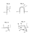
- FIG. 9 An alternative arrangement is shown in Figure 9 , in which the ink-receiving orifice of the gutter is formed as a hole in the side of a curved pipe joining the gutter line 17 and the air recirculation line 37. Because the ink enters a curved section of pipe in a near-tangential direction, it is less likely to splash back out through the hole by which it entered.
- Figures 4 and 7 show the direction of the bore 15a as parallel with the direction of the ink jet 7.
- the bore or pipe which the ink jet 7 enters it is possible for the bore or pipe which the ink jet 7 enters to be angled slightly compared with the direction of the ink jet.
- the ink jet strikes the internal wall of the pipe or bore at an oblique angle to form a liquid film which can then coalesce and be sucked away along the gutter line 17. This slows the ink jet, and reduces the tendency of ink to splash out of the gutter orifice.
- Figures 10 and 11 show such arrangements, made using pipes and made using a gutter block 19, respectively.
- gutter arrangement has been shown both made from pipes and made by forming bores in a gutter block 19, it is at present preferred to use the embodiments formed from a gutter block 19 for reasons of ease of manufacture, ease of mounting and robustness in use.
- the gutter constructions shown are merely examples, and a wide variety of arrangements are possible.
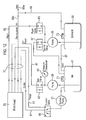
- Figure 12 is a conceptual schematic diagram of the fluid system for an ink jet printer embodying the present invention.
- a fluid system may be designed to perform the necessary operations, and in practice the applicants prefer at present to use a fluid system based on the schematic diagram of Figure 13 .
- the functions and operations of the fluid system are more easily understood with reference to Figure 12 .
- an ink pump 39 draws ink from an ink tank 41 and pressurises it.
- the pressure of the pressurised ink is measured by a pressure transducer 43.
- An ink valve 45 is placed in its open position, with result that pressurised ink flows along an ink feed line 47 through the conduit 31 to the printhead 25.
- the pressurised ink is supplied to the ink gun in order to form the ink jet 7 as described above with reference to Figures 1 and 2 .
- the gutter line 17 is connected through a suction valve 49 to the inlet of a suction pump 51, so that suction from the suction pump 51 is applied to the gutter 15 in the printhead 25.
- the velocity of the ink jet 7 is monitored in a known manner using the sensor electrodes combined with the deflection electrode 13 mentioned above with reference to Figures 1 and 2 .
- the speed of the ink pump 39 is adjusted in order to keep the jet velocity within a desired range. In practice, it may be convenient to control the pump 39 in response to the output of the pressure transducer 43, so as to keep the ink at or near a target pressure, and the target pressure may be adjusted in order to keep the jet velocity in the desired range. As solvent evaporates from the ink, it becomes more viscous and the output pressure from the ink pump 39 has to increase in order to maintain the velocity of the ink jet 7.
- a solvent pump 55 When a predetermined pressure limit is exceeded, a solvent pump 55 is operated and a top-up valve 57 is opened briefly to allow a small volume of solvent to be transferred by the solvent pump 55 from a solvent tank 59 to the ink tank 41, thereby diluting the ink slightly.
- the suction valve 49 can be operated to switch the suction from the suction pump 51 from the gutter line 17 to a purge line 61.
- This line is connected to the interior of the ink gun in the printhead 25, allowing suction to be applied to the ink gun. This can be used for attempting to suck the ink nozzle clear if it has become blocked.
- the suction valve 49 is operated to switch suction to the purge line 61 simultaneously with the closure of the ink valve 45, thereby stopping the flow of ink along the ink feed line 47, the pressure of ink in the ink gun of the printhead can be lowered very abruptly, enabling the ink jet 7 to be stopped cleanly so as to minimise the soiling of the printhead with ink which would happen if the pressure of ink in the ink gun reduced more gradually.
- the printer may perform a cleaning routine in which, after the ink jet has been stopped, suction is maintained on the purge line 61 briefly to suck all the ink out of the ink gun and deliver it back to the ink tank 41.
- the suction valve 49 is then switched to apply suction to the gutter line 17, the solvent pump 55 is operated, and a flush valve 63 is opened to allow solvent to be pumped from the solvent tank 59 along a flush line 65 to the printhead 25.
- the flush line 65 delivers the solvent to the ink gun, and a jet of solvent is formed in place of the ink jet 7.
- the solvent jet enters the gutter 15 and the solvent is then sucked along the gutter line 17.
- the suction pump 51 delivers a mixture of air and ink from the gutter line 17 to the ink tank 41. Consequently, the volume delivered to the ink tank 41 by the suction pump 51 greatly exceeds the volume removed from the ink tank 41 by the ink pump 39, and accordingly the suction pump 51 tends to pressurise the ink tank 41.
- the ink tank 41 is vented by a vent line 67 to the solvent tank 59.
- the solvent tank 59 is in turn vented by an air recirculation line 69.
- this air recirculation line 69 branches, with one branch 69a allowing some of the air from the solvent tank 59 to vent to atmosphere while the other branch 69b conveys recirculated air to the pipe 37 in the printhead.
- the air recirculation pipe 37 in the printhead cannot carry all of the air which the suction pump 51 delivers to the ink tank 41. Accordingly, it is necessary to provide some arrangement for venting part of the air to atmosphere and this is most conveniently done by providing the branch 69a in the air recirculation line 69.
- caps 71, 73 can be designed so that the amount of venting they permit is consistent or controllable, it is now preferred to make these caps airtight and to provide the venting to atmosphere through an arrangement such as the branch line 69a which allows the designer of the ink jet printer to control more easily the proportion of the air from the ink tank 41 which is recirculated to the printhead 25.
- the air recirculation line 69 can be connected so as to take air directly from the ink tank 41 rather than the solvent tank 59, so that the vent line 67 serves to vent the air space in the solvent tank 59, or the vent line 67 could be eliminated entirely and the solvent tank 59 could be vented to atmosphere separately. Since very little air would flow out of the solvent tank 59 if the air recirculation line 69 was connected directly to the ink tank 41, very little solvent would be lost if the solvent tank 59 was vented to atmosphere in an uncontrolled manner.
- the suction pump 51 could deliver the ink and air to a settling or separation tank, from which ink passes to the ink tank 41 and air passes directly to the air recirculation line 69.
- the branch 69a to atmosphere in the air recirculation line 69 can be provided at any convenient location along the length of the air recirculation line 69, either at the main printer body 29 or at the printhead 25.
- the main consideration will be one of user convenience, and if desired the branch 69a may comprise or be connected to a hose or pipe to lead air away to an environmentally preferred venting location.
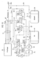
- Figure 13 is a fluid system schematic diagram based on the actual fluid system of a Linx 4900 or Linx 6800 ink jet printer, modified so as to embody the present invention and simplified for ease of comprehension.
- an ink pump 39 takes ink from an ink tank 41. On leaving the pump 39, the ink passes through a 10 micrometre filter 75, to protect the remainder of the fluid system from any particles which may have contaminated the ink in the tank 41.
- the pressure of the ink downstream of the filter 75 is monitored by a pressure transducer 43.
- the pressurised ink then flows through a Venturi suction device 77, in which the flow of ink through the device generates suction using the Venturi effect. Ink discharged from the suction device 77 is returned to the ink tank 41.
- a branch supplies pressurised ink through a damper 79, which damps pressure vibrations in the ink caused by operation of the ink pump 39 and an ink valve 45 to an ink feed line 47.
- the pressurised ink in the ink feed line 47 travels to the printhead 25 and forms the ink jet 7.
- the jet speed is monitored, and the ink pressure provided by the ink pump 39 is controlled accordingly, as discussed with reference to Figure 12 .
- suction from the Venturi suction device 77 is applied to the gutter line 17 through a gutter valve 81, for clearing ink that has entered the gutter 15.
- the suction device 77 Through the normal function of the suction device 77, the ink and air sucked along the gutter line 17 enters the stream of ink passing through the suction device, and therefore passes into the ink tank 41.
- Suction from the Venturi suction device 77 is also applied to the top-up valve 57 via a top-up line 83. Normally, the top-up valve 57 closes the top-up line 83.
- the top-up valve 57 is switched briefly. Consequently, the suction device 77 sucks solvent from the solvent tank 59 through the flush valve 63 and then through the top-up valve 57 into the top-up line 83.
- the solvent then joins the ink flowing through the suction device into the ink tank 41.
- the gutter valve 81 may be switched to apply suction from the suction device 77 to the purge line 61 via a purge valve 85.
- the purge valve 85 allows the purge line 61 to be vented to the ink tank 41 as an alternative to being connected to the gutter valve 81. This allows an additional mode of operation in which ink is pumped from the ink tank 41 along the ink feed line 47, passes to the printhead 25 and then returns along the purge line 61 and flows back into the ink tank 41, without any ink jet being formed in the printhead 25.
- the flush line 65 from the flush valve 63 does not extend to the printhead 25 in the fluid system of Figure 13 , but instead the flush line 65 and the ink feed line 47 are joined within the main printer body 29, and a combined feed line 87 extends to the printhead 25.
- the ink valve 45 is operated to stop the flow of ink along the ink feed line 47
- the gutter valve 81 and the purge valve 85 are placed in positions so as to apply suction from the suction device 77 to the purge line 61
- the flush valve 63 is operated to open the flush line 65. Suction from the suction device 77 is applied via the purge line 61 to the interior of the ink gun in the printhead 25, and this applies suction to the feed line 87.
- This suction cannot suck ink from the ink feed line 47 because the ink valve 45 is closed. Instead, it sucks solvent from the solvent tank 59 through the top-up valve 57 and then through the flush valve 63 into the flush line 65.
- the solvent is then transported by the suction along the feed line 87, through the ink gun and back along the purge line 61, through the suction device 77 and into the ink tank 41.
- the suction is then shut off by operating the gutter valve 81, which returns suction to the gutter line 17.
- the flush valve 63 is operated to isolate the flush line 65, and the ink valve 45 is opened briefly to supply pressurised ink to the ink feed line 47 and the combined feed line 87. This drives some of the solvent already in the feed line 87 out of the orifice in the nozzle portion 5 of the ink gun, to form a brief solvent jet for cleaning the nozzle and the gutter 15.
- Figure 14 shows a simple arrangement in which the air recirculation line 69 has a vent branch 69a through which some of the air is discharged to atmosphere, and a recirculation branch 69b which supplies recirculated air to the air recirculation pipe 37 in the printhead.
- Each branch has a respective flow restrictor 89a, 89b.
- the system designer can exercise a degree of control over the proportion of the air in the recirculation line 69 that is discharged through the branch 69a.
- the flow restrictors 89a, 89b are shown close to the point where the recirculation line 69 branches in Figure 14 , this is not necessary and they can be placed at any convenient location along their respective branch lines.
- the air recirculation line 69 may branch inside the main printer body 29, allowing the vent branch 69a to discharge solvent-laden air to atmosphere at the printer body or via a pipe to a desired location, whereas the flow restrictor 89b in the recirculation branch 69b may be provided at or near the printhead 25.
- a bypass branch 69c is provided, to bypass the flow restrictor 89a in the vent branch 69a that discharges to atmosphere.
- a valve 91 in the bypass branch 69c can be selectively opened or closed in order to provide or remove the bypass effect.
- air in the air recirculation line 69 can flow to atmosphere without passing through the flow restrictor 89a, and accordingly the flow to atmosphere is increased at the expense of the recirculation flow in the air recirculation branch 69b.
- bypass branch 69c is shown as branching from the air recirculation line 69 upstream of the location where it splits into the branches 69a and 69b.
- the bypass branch 69c could alternatively branch out of the vent branch 69a upstream of the flow restrictor 89a.
- the bypass branch 69c is shown in
- FIG. 15 as connecting with the vent branch 69a downstream of the flow restrictor 89a, but it would be possible for the bypass branch 69c to vent to atmosphere independently rather than reconnecting to the vent branch 69a.
- Figure 16 shows an alternative arrangement to the air recirculation line branching arrangement of Figure 15 .
- the flow restrictor 89a in the vent branch 69a is replaced by a flow restriction valve 93. This can be moved between a position in which it significantly restricts flow in the vent branch 69a, to provide a similar effect to the flow restrictor 89a, to a position in which it allows a substantially less restricted flow, thereby permitting an increased proportion of the air in the air recirculation line 69 to be discharged to atmosphere.
- the flow restriction valve 93 is continuously variable between its extreme positions, or has one or more intermediate positions between its most open position and its most flow-restricting position, a finer degree of control can be provided over the proportion of the air in the air recirculation line 69 that is discharged to atmosphere.
- This makes it possible to implement more sophisticated control regimes, such as discharging a high proportion of the air to atmosphere when the ink is highly overdilute, and discharging an intermediate amount of air to atmosphere when the ink is slightly overdilute, enabling a balance to be made between the environmental disadvantage of discharging solvent-laden air to atmosphere and the operational desire to strip excess solvent out of the ink.
- shutoff valve 95 and the recirculation branch flow restrictor 89b may be combined in a flow restriction valve similar to the flow restriction valve 93 discussed with reference to Figure 16 .
- This flow restriction valve could be moved between a position in which it shuts off the recirculation branch 69b entirely or provides a high degree of restriction, and a second position in which it provides a lower degree of restriction or none at all.
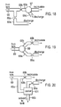
- FIG. 18 A further alternative arrangement is shown in Figure 18 in which the shutoff val ve 95 of Figure 17 is replaced by a switchover valve or flow diverter 97.
- This allows the flow of air entering the recirculation branch 69b to be partially or wholly redirected into an additional discharge branch 69d in order to increase the proportion of air discharged to atmosphere. If a multi-position or continuously variable flow diverter is used, intermediate levels of air discharged to atmosphere can be obtained as well as the maximum and the minimum levels.
- the switchover valve or flow diverter 97 is shown downstream of the recirculation branch flow restrictor 89b, but it can instead be placed upstream of the flow restrictor.
- Figure 18 shows the additional discharge branch 69d as discharging directly to atmosphere. However, it can alternatively be arranged to connect with the vent branch 69a downstream of the vent branch flow restrictor 89a.
- a flow diverter 99 is provided at the junction where the air recirculation line 69 branches into the vent branch 69a and the recirculation branch 69b.
- the flow diverter 99 can be operated to vary the proportion of the air passing along the air recirculation line 69 which is discharged to atmosphere through the vent branch 69a.
- the flow restrictors 89a, 89b are shown in the respective branches 69a, 69b. However, as an alternative these flow restrictors can be omitted and the flow diverter 99 can be made entirely responsible for controlling the relative proportions of recirculated air and discharged air.
- the amount of solvent which is discharged can be reduced by providing a solvent recovery device such as a cooler in the line which conveys the air being discharged to atmosphere.
- Figure 20 shows a modification of the branching arrangement of Figure 14 in which a cooler 101 is provided in the vent branch 69a, to condense solvent out of the air passing along the vent branch 69a and thereby reduce the amount of solvent discharged to atmosphere.
- the recovered solvent may be returned to the solvent tank 59 along a solvent return line 103. It may alternatively be returned to the ink tank 41, in which case the rate of loss of solvent from the ink is reduced. This may be disadvantageous if the ink is currently over-dilute, and therefore return to the solvent tank 59 is preferred.
- the cooler 101 may be implemented in any convenient manner.
- it may be a Peltier cooler.
- it may be a cooler using compression and expansion of a refrigerant.
- a coolant such as water, which has been cooled elsewhere, may be used to cool a pipe or vessel in the vent branch 69a.
- the air pressure inside the solvent tank 59 must be higher than the air pressure inside the cooler 101, in view of the flow of air along the air recirculation line 69.
- This pressure difference may tend to cause an undesirable flow of air from the solvent tank 59 into the cooler 101 along the solvent return line 103. Accordingly, it may be desirable to take steps to prevent this.
- the solvent return line 103 can open into the solvent tank 59 near the bottom of the tank rather than near the top of the tank, so that the open end of the solvent return line 103 is below the surface of the solvent in the tank 59.
- the solvent return line 103 may discharge into a separate solvent recovery tank, rather than the solvent tank 59 of the printer, allowing the recovered solvent to be processed in an environmentally suitable manner.
- the cooler 101 has been shown upstream of the flow restrictor 89a, but it can be provided instead downstream of the flow restrictor. Additionally, the cooler 101 can be provided in the vent branch 69a of any of the alternative branching arrangements discussed with reference to Figures 15 to 19 , and in the additional discharge branch 69d of Figure 18 .
- Figure 20 shows a cooler used as a solvent recovery device
- any suitable alternative arrangement may be used.
- valves or flow diverters 91, 93, 95, 97, 99 may be under manual control by the operator, or alternatively if a motor or other operating mechanism is provided they may be controlled automatically by the ink jet printer control system in response to the ink viscosity as determined from the measured ink jet velocity and the ink pressure (or as determined in any other way, such as by a viscosimeter if one is fitted), or in accordance with any other suitable control procedure such as an arrangement which monitors whether a flushing operation has been performed recently, or the printer may be programmed to increase the proportion of air discharged to atmosphere automatically for a certain length of time whenever the printer is restarted after being turned off. It may also be controlled in accordance with changes in the level of suction applied to the gutter.
- Figure 21 shows schematically the arrangement of an ink jet printer control system which would be able to control the valve or flow diverter in this manner.
- the control system 105 has input/output circuitry 107 through which it can send control signals to the valve or flow diverter 91, 93, 95, 97 or 99, send signals to and receive signals from the electrodes and other components in the printhead 25, receive ink pressure values from the pressure transducer 43, control the ink pump 39, and communicate with other components and devices such as the display 33, the keypad 35 and the various valves of the fluid system.
- the control system 105 further includes a microprocessor 109, a program ROM 111 storing a program for controlling the microprocessor 109, a random access memory 113 for providing a working memory for the microprocessor 109, and a non-volatile random access memory 115 for storing variable data which the printer needs to retain while it is turned off, such as setup and control information relating to its current configuration and the data to be printed, which may be entered by the operator through the keypad 35 or in any other convenient manner.
- These components of the control system 105 communicate with each other via a bus 117.
- the microprocessor 109 communicates via the input/output circuitry 107 with the printhead electrodes and other components so as to perform, amongst other tasks, a "time of flight" measurement operation in which ink drops are given a very slight charge, which still permits them to pass to the gutter, and the charged drops are detected as they pass two spaced apart sensor electrodes in the printhead. The time taken for the drops to pass from one sensor electrode to the other is measured to obtain the time of flight, which provides a measure of jet speed.
- a "time of flight” measurement operation in which ink drops are given a very slight charge, which still permits them to pass to the gutter, and the charged drops are detected as they pass two spaced apart sensor electrodes in the printhead.
- the time taken for the drops to pass from one sensor electrode to the other is measured to obtain the time of flight, which provides a measure of jet speed.
- the microprocessor 109 will monitor the pressure values received from the pressure transducer 43 continuously during normal operation of the printer, and these detected pressure values will be compared with a target pressure value stored in the RAM 113.
- the control signals sent to the ink pump 39 will speed the pump up or slow it down depending on the difference between the ink pressure values received from the pressure transducer 43 and the stored target value. From time to time the microprocessor 109 will compare the "time of flight" value obtained from the measurement operation described above with a target value stored in RAM 113 or NVRAM 115.
- the target pressure value used to control the ink pump 39 is adjusted if the measured time of flight differs from the target time of flight by m ore than a permitted margin. In this way, the microprocessor 109 keeps the ink jet velocity at or close to the target value.
- a permitted range for the ink pressure is also stored in RAM 113 or NVRAM 115. If the target pressure set into the RAM 113, in order to maintain the correct time of flight, exceeds the top of the permitted pressure range, the microprocessor 109 controls the fluid system components such as the valves so as to perform an operation for transferring solvent from the solvent tank 59 into the ink, so as to dilute it. If the target pressure written into the RAM 113 falls below the minimum permitted value, this indicates that the ink contains too much solvent and the microprocessor sends signals to the valve or flow diverter 91, 93, 95, 97 or 99 to increase the amount of air vented to atmosphere in order to accelerate the rate at which solvent is lost from the ink. As discussed above, depending on the extent to which the valve or flow diverter is controllable, the microprocessor 109 may control its position in accordance with the extent to which the target ink pressure value falls below the permitted range.
- the program stored in ROM 111 for controlling the microprocessor 109, may be arranged so that the microprocessor automatically controls the valve or flow diverter to increase the amount of air vented to atmosphere temporarily whenever the ink jet is restarted having been turned off.
- the printhead flushing operation discussed above is carried out under the control of the microprocessor 109 and the program may be arranged so that the microprocessor stores in NVRAM 115 the fact that such an operation has been carried out, and subsequently uses that information together with information about how long the jet has been running to evaluate the likelihood that the ink contains excessive solvent, and to control the valve or flow diverter accordingly.
- These various rules and arrangements by which the microprocessor 109 controls the valve or flow diverter 91, 93, 95, 97 or 99 may be used as alternatives to one another or may be used in conjunction, according to the wishes of the designer of the ink jet printer concerned.
- a Linx 6800 printer was fitted with a Linx Ultima printhead modified to provide recirculation back to the printhead of air which has passed down the gutter line and through the ink and solvent tanks.
- the recirculation was achieved by drilling an additional bore into the gutter block, to intercept the gutter bore, and the air recirculation line was connected to this additional bore, in accordance with the embodiment of Figures 1 and 2 and Figures 4 to 6 .
- the printer was set up to run with Linx 3103 ink and 3501 solvent, which is a system based on a mixture of ethanol and acetone.
- the caps and associated filler tubes for the ink and solvent tanks were replaced with turned plugs to prevent any uncontrolled venting to atmosphere.
- the printer body, conduit, printhead and power cable were weighed with the printer ready to operate. Then the printer was set to operate with the jet running continuously but without printing, so that the jet was always directed into the gutter. The printer, conduit and printhead sat on weighing scales throughout the experiment so that their combined weight could be monitored. At the end of the test, after the printer had been shut down, the combination of printer body, conduit, printhead and the power cable was weighed again.
- the branch line venting some of the air to atmosphere was initially fitted with a very small flow restrictor (having an internal diameter of about 0.25mm), and this resulted in the ink not being adequately sucked clear of the gutter, so that ink spilled out of the gutter orifice.
- Subsequent tests were conducted with matching flow restrictors, each having an internal diameter of 0.6mm, in the vent branch line taking air to atmosphere and the recirculation branch line delivering recirculated air to the gutter block.
- the gutter line had an internal diameter of 1.6mm
- the air recirculation line had an internal diameter of 3.0mm
- the air recirculation path within the gutter block, where it opens into the gutter had an internal diameter of 1.0mm.
- Solvent consumption was then tested with the air recirculation system in place, and 0.6mm flow restrictors as discussed above in both the line delivering recirculated air to the gutter block and the line venting air to atmosphere. This arrangement was tested twice. On the first occasion, approximately 29 grams of solvent were consumed during seven hours and on the second occasion approximately 27 grams of solvent were consumed in seven hours. Accordingly, these experiments indicated a reduction in solvent consumption to about 50% of the amount consumed when the printer was not modified.
- the printer was set up so that none of the air passing down the gutter line was recirculated back to the printhead, but the line venting the air to atmosphere was fitted with a flow restrictor in the same way as in the experiments conducted with air recirculation. In this case, there was a solvent consumption of approximately 56 grams during seven hours. This shows that using a flow restrictor to reduce the rate at which air flows in through the gutter orifice and along the gutter line has some effect on the rate of consumption of solvent, but most of the reduction in solvent consumption shown in the experiments appears to be attributable to the recirculation of air back to the gutter block.
- a separate vent line may be provided direct from the ink tank 41, the solvent tank 59 or any other convenient location downstream of the suction source 51, 77.
- the bypass and valve arrangements of Figures 15 and 16 , and the solvent recovery system of Figure 20 may be applied to the vent line, and the valve and diverter arrangements of Figures 17 and 18 may be applied to the recirculation line.
- the suction source may apply suction to the ink tank (which would not be separately vented). Suction is still applied to the gutter, but in this case the suction is applied via the air space in the ink tank.
- the suction pump 51 could be moved to be in the line 67 or in the line 69 before it branches. If the suction pump is in the recirculation line 69, this line may be connected directly to the ink tank instead of to the solvent tank, as discussed above.
- the above embodiments show ink jet printer arrangements in which a printhead is connected to a printer body via a flexible conduit, since this is the most common arrangement in practice, but the invention is not limited to this.
- the ink gun, the electrodes 9, 11, 13, the gutter 15 and all the other printhead components may be in the same housing as the tanks and other fluid system components.
- the gutter line 17, the air recirculation line 69 and all the other lines which would normally pass along the conduit may be fluid connection lines that are contained wholly within the housing.
- the printhead may be fixed directly to the printer body without any conduit.
Landscapes
- Engineering & Computer Science (AREA)
- Quality & Reliability (AREA)
- Particle Formation And Scattering Control In Inkjet Printers (AREA)
- Ink Jet (AREA)
- Percussion Or Vibration Massage (AREA)
- Environmental & Geological Engineering (AREA)
Claims (21)
- Mit kontinuierlichem Strahl arbeitender Tintenstrahldrucker mit einer Tintenstrahleinrichtung zur Bildung eines Tintenstrahls (7) und einer Abzug-Einrichtung (15) zur Aufnahme von Tintentropfen des Tintenstrahls durch eine Tinte aufnehmende der Abzug-Einrichtung, wobei diese Tintentropfen nicht zum Drucken verwendet werden,
wobei der Drucker einen Abzug-Einrichtungs-Strömungspfad (15a, 15b, 17) beginnend an der die Tinte aufnehmenden Öffnung für Tinte aufweist, die in die Abzug-Einrichtung durch die Tinte aufnehmende Öffnung eingetreten ist,
dadurch gekennzeichnet, dass
der Drucker weiterhin eine Luftleitung (69) aufweist, die sich in den Abzug-Strömungspfad an einer Position stromabwärts von der die Tinte aufnehmenden Öffnung öffnet, um Luft, die mit der Tinte entlang zumindest eines Teils des Abzug-Strömungspfades mitgenommen wurde, so zu fördern, dass sie erneut in den Abzug-Strömungspfad an der genannten Position eintritt. - Mit kontinuierlichem Strahl arbeitender Tintenstrahldrucker nach Anspruch 1, der eine Entlüftung zum Entlüften zumindest eines Teils der Luft umfasst, die von der Tinte entlang zumindest eines Teils des Abzug-Strömungspfades mitgenommen wurde, so dass sie nicht erneut in den Abzug-Strömungspfad eintritt.
- Mit kontinuierlichem Strahl arbeitender Tintenstrahldrucker nach Anspruch 2, der einen Tank (41) für in dem Tintenstrahl zu verwendender Tinte und einen Tank (59) für zum Verdünnen der Tinte zu verwendendes Lösungsmittel aufweist, wobei die Tanks jeweilige Verschlussdeckel (71, 73) aufweisen, die zum Nachfüllen zu öffnen sind, und wobei der Drucker so angeordnet ist, dass er Luft, die entlang des Abzug-Strömungspfades geströmt ist, an den Tintentank liefert,
wobei die Entlüftung zumindest teilweise einen Pfad für Luft umfasst, die durch ein Fehlen einer Luftdichtigkeit der Verschlusskappe eines der Tanks zugeführt wurde. - Mit kontinuierlichem Strahl arbeitender Tintenstrahldrucker nach Anspruch 2 oder 3, mit einer oder mehreren Strömungs-Steuereinrichtungen (91, 93, 95, 97, 99) zur Änderung der relativen Anteile der Luft, die entlang zumindest eines Teils des Abzug-Strömungspfades geströmt ist, der durch die Entlüftung entlüftet wird, oder die entlang der Luftleitung gefördert wird.
- Mit kontinuierlichem Strahl arbeitender Tintenstrahldrucker nach Anspruch 4, der weiterhin ein Steuersystem umfasst, das zur automatischen Steuerung des Zustandes der einen oder der mehreren Strömungs-Steuereinrichtungen oder zumindest von einer hiervon in Abhängigkeit von einem oder mehreren festgestellten Zuständen des Druckers und/oder einer oder mehreren vergangenen Betriebsvorgängen des Druckers angeordnet ist.
- Mit kontinuierlichem Strahl arbeitender Tintenstrahldrucker nach einem der Ansprüche 2 bis 5, der zumindest eine erste Betriebsart, in der ein von der Tintenstrahleinrichtung ausgestoßener Tintenstrahl und zumindest ein Teil der Luft, die entlang eines Teils des Abzug-Strömungspfades geströmt ist, entlang der Luftleitung gefördert wird, um erneut in den Abzug-Strömungspfad einzutreten, und eine zweite Betriebsart aufweist, in der ein Tintenstrahl von der Tintenstrahleinrichtung ausgestoßen wird und zumindest ein Teil der Luft, der entlang zumindest eines Teils des Abzug-Strömungspfades geströmt ist, über die Entlüftung entlüftet wird, wobei der Anteil der Luft von dem Abzug-Strömungspfad, der entlang der Luftleitung gefördert wird, um in den Abzug-Strömungspfad in der zweiten Betriebsart erneut einzutreten, in der zweiten Betriebsart entweder Null oder kleiner als der Anteil in der ersten Betriebsart ist.
- Mit kontinuierlichem Strahl arbeitender Tintenstrahldrucker nach einem der vorhergehenden Ansprüche, der eine Anordnung von Elektroden (9, 11, 13) zum Einfangen elektrischer Ladungen auf Tintentropfen des Tintenstrahls und zum Erzeugen eines elektrostatischen Feldes zum Ablenken von Tropfen umfasst, die eingefangene elektrische Ladungen tragen.
- Abzug-Einrichtung für einen mit kontinuierlichem Strahl arbeitenden Tintenstrahldrucker, wobei die Abzug-Einrichtung Folgendes aufweist:einen ersten umschlossenen Strömungsmittel-Strömungspfad (15a, 15b) durch die Abzug-Einrichtung, der sich von einem ersten Ende zu einem zweiten Ende erstreckt, wobei das erste Ende des umschlossenen Strömungsmittel-Strömungspfades zur Aufnahme von Tintentropfen eines Tintenstrahls des Druckers im Betrieb geeignet ist und das zweite Ende des ersten umschlossenen Strömungsmittel-Strömungspfades zur Verbindung mit einer Saugleitung (17) zum Absaugen von Tinte in dem ersten umschlossenen Strömungspfad geeignet ist, dadurch gekennzeichnet, dass er weiterhin Folgendes aufweist:einen zweiten umschlossenen Strömungsmittel-Strömungspfad (37a) durch die Abzug-Einrichtung, der sich von einem ersten Ende zu einem zweiten Ende erstreckt, wobei das erste Ende des zweiten umschlossenen Strömungsmittel-Strömungspfades zur Verbindung mit einer Leitung (37, 69) zur Lieferung von Luft an den zweiten Strömungsmittel-Strömungspfad geeignet ist, und das zweite Ende des zweiten Strömungsmittel-Strömungspfades sich in den ersten umschlossenen Strömungsmittel-Strömungspfad an einer Position innerhalb der Abzug-Einrichtung und zwischen den ersten und zweiten Enden des ersten Strömungsmittel-Strömungspfades öffnet.
- Mit kontinuierlichem Strahl arbeitender Tintenstrahldrucker nach einem der Ansprüche 1 bis 7, oder eine Abzug-Einrichtung nach Anspruch 8, bei dem die Position stromabwärts von der Tinte aufnehmenden Öffnung in einem Abstand von nicht mehr als 10mm, bzw. bei der die Position in einem Abstand von nicht mehr als 10mm entlang des ersten umschlossenen Strömungsmittel-Strömungspfades von dessen ersten Ende aus liegt.
- Mit kontinuierlichem Strahl arbeitender Tintenstrahldrucker oder ein Abzug-Einrichtung nach Anspruch 9, bei dem bzw. bei der der Abstand nicht größer als 5 Millimeter ist.
- Mit kontinuierlichem Strahl arbeitender Tintenstrahldrucker oder Abzug -Einrichtung nach Anspruch 9, bei dem bzw. bei der der Abstand nicht größer als 2 Millimeter ist.
- Druckerkopf für einen mit kontinuierlichem Strahl arbeitenden Tintenstrahldrucker, mit einer Tintenstrahleinrichtung zur Bildung eines Tintenstrahls und einer Abzug-Einrichtung nach einem der Ansprüche 8 bis 11 zur Aufnahme von Tintentropfen des Tintenstrahls, die nicht zum Drucken verwendet werden.
- Mit kontinuierlichem Strahl arbeitender Tintenstrahldrucker nach einem der Ansprüche 1 bis 7 oder nach einem der Ansprüche 9, bis 11, mit einem Druckerkopf (25), einem Drucker-Hauptteil (29) und einer flexiblen Leitung (31), die zwischen diesen angeschlossen ist,
wobei die Tintenstrahleinrichtung und die Abzug-Einrichtung in dem Druckerkopf angeordnet sind,
wobei der Abzug-Strömungspfad (17) und die Luftleitung (69) durch die Leitung hindurchlaufen, und
wobei Drucker-Hauptteil eine Saugquelle (51, 57) aufweist, die zum Aufbringen einer Saugkraft auf die Abzug-Einrichtung über den Abzug-Strömungspfad angeschlossen ist. - Druckerkopf für einen mit kontinuierlichem Strahl arbeitenden Tintenstrahldrucker nach Anspruch 13, der eine Abzug-Einrichtung nach einem der Ansprüche 8 bis 11 umfasst, wobei die Abzug-Einrichtung einen umschlossenen Tintenpfad (15a, 15b) beginnend von der die Tinte aufnehmenden Öffnung bereitstellt, der einen Teil des Abzug-Strömungspfades bildet und einen umschlossenen Luftpfad (37a) zur Aufnahme von Luft bereitstellt, die entlang einer Luftzirkulationsleitung gefördert wurde, wobei sich der umschlossene Luftpfad in den umschlossenen Tintenpfad an der Position stromabwärts von der die Tinte aufnehmenden Öffnung öffnet.
- Verfahren zum Betrieb eines mit kontinuierlichem Strahl arbeitenden Tintenstrahldruckers, mit den folgenden Schritten:Bilden eines Tintenstrahls (7);Aufnehmen von Tintentropfen des Tintenstrahls (7), wobei diese Tropfen nicht zum Drucken verwendet werden, in einer Abzug-Einrichtung (15) über eine die Tinte aufnehmende Öffnung der Abzug-Einrichtung; undFördern von Tinte, die in die Abzug-Einrichtung durch die die Tinte aufnehmende Öffnung eingetreten ist, entlang eines Abzug-Strömungspfades (15a, 15b, 17);gekennzeichnet durch:Rezirkulieren eines Teils der Luft, die entlang zumindest eines Teils des Abzug-Strömungspfades geströmt ist, derart, dass sie erneut in den Abzug-Strömungspfad an einer Position stromabwärts von der die Tinte aufnehmenden Öffnung eintritt.
- Verfahren nach Anspruch 15, bei dem die Position stromabwärts von der die Tinte aufnehmenden Öffnung in einem Abstand von nicht mehr als 10mm liegt.
- Verfahren nach Anspruch 15, bei dem die Position stromabwärts von der die Tinte aufnehmenden Öffnung in einem Abstand von nicht mehr als 5mm liegt.
- Verfahren nach Anspruch 15, bei dem die Position stromabwärts von der die Tinte aufnehmenden Öffnung in einem Abstand von nicht mehr als 2mm liegt.
- Verfahren nach einem der Ansprüche 15 bis 18, die das Entlüften eines Teils der Luft umfasst, die entlang zumindest eines Teils des Abzug-Strömungspfades geströmt ist, so dass sie nicht erneut in den Abzug-Strömungspfad eintritt.
- Verfahren nach Anspruch 19, das weiterhin eine Änderung der relativen Anteils der Luft, die rezirkuliert wird, und der Luft, die entlüftet wird, umfasst.
- Verfahren nach einem der Ansprüche 15 bis 20, das das Einfangen elektrischer Ladungen auf Tintentropfen des Tintenstrahls und das Erzeugen eines elektrostatischen Feldes zum Ablenken von Tropfen umfasst, die die eingefangenen elektrischen Ladungen tragen.
Priority Applications (1)
| Application Number | Priority Date | Filing Date | Title |
|---|---|---|---|
| EP10192377A EP2292433B1 (de) | 2007-03-27 | 2008-03-12 | Tintenstrahldrucken |
Applications Claiming Priority (2)
| Application Number | Priority Date | Filing Date | Title |
|---|---|---|---|
| GB0705902.5A GB2447919B (en) | 2007-03-27 | 2007-03-27 | Ink jet printing |
| PCT/GB2008/000836 WO2008117013A1 (en) | 2007-03-27 | 2008-03-12 | Ink jet printing |
Related Child Applications (2)
| Application Number | Title | Priority Date | Filing Date |
|---|---|---|---|
| EP10192377A Division EP2292433B1 (de) | 2007-03-27 | 2008-03-12 | Tintenstrahldrucken |
| EP10192377.9 Division-Into | 2010-11-24 |
Publications (2)
| Publication Number | Publication Date |
|---|---|
| EP2125376A1 EP2125376A1 (de) | 2009-12-02 |
| EP2125376B1 true EP2125376B1 (de) | 2011-01-05 |
Family
ID=38050302
Family Applications (2)
| Application Number | Title | Priority Date | Filing Date |
|---|---|---|---|
| EP08718682A Revoked EP2125376B1 (de) | 2007-03-27 | 2008-03-12 | Tintenstrahldruck |
| EP10192377A Active EP2292433B1 (de) | 2007-03-27 | 2008-03-12 | Tintenstrahldrucken |
Family Applications After (1)
| Application Number | Title | Priority Date | Filing Date |
|---|---|---|---|
| EP10192377A Active EP2292433B1 (de) | 2007-03-27 | 2008-03-12 | Tintenstrahldrucken |
Country Status (7)
| Country | Link |
|---|---|
| US (2) | US8388118B2 (de) |
| EP (2) | EP2125376B1 (de) |
| CN (1) | CN101668639B (de) |
| AT (1) | ATE494149T1 (de) |
| DE (1) | DE602008004322D1 (de) |
| GB (1) | GB2447919B (de) |
| WO (1) | WO2008117013A1 (de) |
Cited By (1)
| Publication number | Priority date | Publication date | Assignee | Title |
|---|---|---|---|---|
| US10414155B2 (en) | 2014-06-05 | 2019-09-17 | Videojet Technologies Inc. | Continuous ink jet print head with zero adjustment embedded charging electrode |
Families Citing this family (60)
| Publication number | Priority date | Publication date | Assignee | Title |
|---|---|---|---|---|
| GB2447919B (en) | 2007-03-27 | 2012-04-04 | Linx Printing Tech | Ink jet printing |
| GB2455775B (en) * | 2007-12-21 | 2012-07-18 | Linx Printing Tech | Inkjet printer and flow restriction system therefor |
| EP2241442B1 (de) † | 2008-01-28 | 2011-10-26 | Hitachi Industrial Equipment Systems Co., Ltd. | Tintenstrahlaufzeichnungsvorrichtung |
| CN102123869A (zh) * | 2008-08-15 | 2011-07-13 | 录象射流技术公司 | 用于喷墨打印机的冷凝器 |
| FR2956061B1 (fr) * | 2010-02-11 | 2012-12-21 | Markem Imaje | Imprimante a jet d'encre industrielle a communication numerique |
| JP5166487B2 (ja) | 2010-06-30 | 2013-03-21 | 株式会社日立産機システム | インクジェット記録装置及びインクジェット記録装置のエアパージ制御方法 |
| US8348406B2 (en) | 2010-07-30 | 2013-01-08 | Xerox Corporation | Liquid ink delivery system including a flow restrictor that resists air bubble formation in a liquid ink reservoir |
| US8506061B2 (en) | 2010-08-23 | 2013-08-13 | Xerox Corporation | Method and apparatus for purging and supplying ink to an inkjet printing apparatus |
| JP2012045749A (ja) * | 2010-08-25 | 2012-03-08 | Hitachi Industrial Equipment Systems Co Ltd | インクジェット記録装置 |
| US8550612B2 (en) | 2010-10-20 | 2013-10-08 | Xerox Corporation | Method and system for ink delivery and purged ink recovery in an inkjet printer |
| WO2012060815A1 (en) | 2010-11-01 | 2012-05-10 | Hewlett-Packard Development Company, L.P. | Printer vapor treatment preheating |
| GB201019679D0 (en) | 2010-11-19 | 2011-01-05 | Domino Printing Sciences Plc | Improvements in or relating to inkjet printers |
| US8403457B2 (en) | 2011-02-04 | 2013-03-26 | Xerox Corporation | Waste ink reclamation apparatus for liquid ink recirculation system |
| CN102218932A (zh) * | 2011-05-18 | 2011-10-19 | 张家港金米兰德龙机械有限公司 | 喷码机用墨水回收装置 |
| JP6003034B2 (ja) | 2011-09-20 | 2016-10-05 | セイコーエプソン株式会社 | 液体吐出装置、及び、液体循環方法 |
| JP5743832B2 (ja) * | 2011-09-30 | 2015-07-01 | 株式会社日立産機システム | インクジェット記録装置 |
| JP5796459B2 (ja) | 2011-11-07 | 2015-10-21 | セイコーエプソン株式会社 | 印刷装置、及び、ホワイトインク循環方法 |
| JP5796458B2 (ja) | 2011-11-07 | 2015-10-21 | セイコーエプソン株式会社 | 液体吐出装置、及び、液体循環方法 |
| JP5938891B2 (ja) * | 2011-12-20 | 2016-06-22 | セイコーエプソン株式会社 | 印刷装置、及び、液体移送方法 |
| US8662649B2 (en) | 2012-01-18 | 2014-03-04 | Xerox Corporation | Method and system for printing recycled ink with process black neutralization |
| JP5880076B2 (ja) * | 2012-01-25 | 2016-03-08 | セイコーエプソン株式会社 | 記録装置 |
| ITMO20120093A1 (it) * | 2012-04-05 | 2013-10-06 | System Spa | Sistema di alimentazione per stampanti a getto di inchiostro. |
| US9227421B2 (en) | 2012-05-14 | 2016-01-05 | Videojet Technoogies Inc. | Ink jet printer |
| US9044954B1 (en) * | 2012-05-14 | 2015-06-02 | Videojet Technologies Inc. | Ink jet printer |
| EP2849951B1 (de) * | 2012-05-14 | 2018-07-11 | Videojet Technologies Inc. | Tintenstrahldrucker |
| US8840230B2 (en) | 2012-06-04 | 2014-09-23 | Xerox Corporation | Ink waste tray configured with one way filter |
| JP5940005B2 (ja) * | 2013-03-08 | 2016-06-29 | 株式会社日立産機システム | インクジェット記録装置 |
| JP6175005B2 (ja) * | 2014-01-16 | 2017-08-02 | 株式会社キーエンス | インクジェット記録装置 |
| DE102014204190A1 (de) * | 2014-03-07 | 2015-09-10 | Bundesdruckerei Gmbh | Druckmodul, Verfahren zum Bedrucken und Druckeinrichtung |
| WO2015187839A1 (en) | 2014-06-05 | 2015-12-10 | Videojet Technologies Inc. | A self-sealing filter module for inkjet printing |
| EP3152058B1 (de) | 2014-06-05 | 2018-12-19 | Videojet Technologies Inc. | Sensoranordnung für tintenaufbau |
| JP6355477B2 (ja) * | 2014-08-21 | 2018-07-11 | キヤノン株式会社 | インクジェット記録装置 |
| GB2540111A (en) * | 2014-11-25 | 2017-01-11 | Matricode Ltd | Fluids delivery system |
| CN104608492B (zh) * | 2015-02-12 | 2016-10-05 | 京东方科技集团股份有限公司 | 一种喷墨打印机的维护方法及维护系统 |
| JP6459594B2 (ja) * | 2015-02-13 | 2019-01-30 | セイコーエプソン株式会社 | 液滴吐出装置 |
| JP6520247B2 (ja) | 2015-03-13 | 2019-05-29 | セイコーエプソン株式会社 | 液体噴射装置 |
| JP6547393B2 (ja) * | 2015-04-27 | 2019-07-24 | セイコーエプソン株式会社 | 液体噴射装置 |
| GB201510456D0 (en) * | 2015-06-15 | 2015-07-29 | Videojet Technologies Inc | Apparatus for printing |
| CN105437772B (zh) * | 2015-12-17 | 2017-06-20 | 重庆宏劲印务有限责任公司 | 一种喷墨打印机喷头清洗装置 |
| FR3045459B1 (fr) | 2015-12-22 | 2020-06-12 | Dover Europe Sarl | Tete d'impression ou imprimante a jet d'encre a consommation de solvant reduite |
| JP6594194B2 (ja) * | 2015-12-24 | 2019-10-23 | 株式会社Screenホールディングス | インクジェットプリンタおよび送液状態確認方法 |
| JP6686592B2 (ja) * | 2016-03-22 | 2020-04-22 | セイコーエプソン株式会社 | 洗浄液供給装置およびこれを備えた液滴吐出装置 |
| GB2551321B (en) * | 2016-06-07 | 2021-06-09 | Linx Printing Tech | Ink jet printer |
| GB2552313A (en) * | 2016-07-14 | 2018-01-24 | Domino Uk Ltd | Improvements in or relating to continuous inkjet printers |
| DE102016012574A1 (de) * | 2016-10-21 | 2018-04-26 | Merck Patent Gmbh | Verfahren zum Betreiben einer Druckvorrichtung und Druckvorrichtung |
| EP3562673B1 (de) * | 2016-12-27 | 2020-12-30 | Sicpa Holding Sa | Tintenstrahldruckkopfvorrichtung und verfahren und system zur detektion von tintenleckage |
| CN110325372B (zh) * | 2017-04-05 | 2022-02-18 | 惠普发展公司,有限责任合伙企业 | 流体喷射装置、打印杆和流体流动结构 |
| CN107199774A (zh) * | 2017-05-03 | 2017-09-26 | 中山市神彩数字印花设备有限公司 | 一种喷墨系统及其操作方法 |
| DE102017215434A1 (de) * | 2017-09-04 | 2019-03-07 | Krones Ag | Klimatisierung von Direktdruckmaschinen |
| JP7066859B2 (ja) * | 2018-08-29 | 2022-05-13 | 株式会社日立産機システム | インクジェット記録装置 |
| DE102018007916A1 (de) * | 2018-10-08 | 2020-04-09 | Jan Franck | Zirkulationsvorrichtung für ein flüssiges Stoffgemisch in einem Behälter |
| US10632757B1 (en) * | 2018-12-10 | 2020-04-28 | Xerox Corporation | System and method for attenuating the drying of ink from a printhead during idle periods |
| JP2021003811A (ja) * | 2019-06-25 | 2021-01-14 | 株式会社日立製作所 | インクジェット記録装置 |
| JP7312098B2 (ja) * | 2019-12-12 | 2023-07-20 | 株式会社キーエンス | インクジェット記録システム |
| WO2021160385A1 (en) * | 2020-02-13 | 2021-08-19 | Memjet Technology Limited | Method and system for priming dry printheads |
| CN111332018B (zh) * | 2020-03-10 | 2021-04-06 | 泰州市博达机械制造有限公司 | 一种用于纸盒生产的环保印刷机械设备 |
| EP4023444B1 (de) | 2020-12-30 | 2024-09-18 | Dover Europe Sàrl | Reinigungsverfahren für den hydraulikkreis eines tintenstrahldruckers |
| GB2605788A (en) | 2021-04-12 | 2022-10-19 | Linx Printing Tech | Continuous inkjet printer |
| GB2606168B (en) * | 2021-04-27 | 2025-01-22 | Domino Uk Ltd | Wash valve |
| US11884076B2 (en) * | 2021-05-10 | 2024-01-30 | Applied Materials, Inc. | Fluid management system for inkjet machines |
Family Cites Families (76)
| Publication number | Priority date | Publication date | Assignee | Title |
|---|---|---|---|---|
| US3055856A (en) * | 1958-12-30 | 1962-09-25 | Copolymer Rubber & Chem Corp | Aqueous suspension of carbon black, apparatus and method for preparing same, method for mixing same with rubber, and product obtained thereby |
| US4023182A (en) * | 1975-08-22 | 1977-05-10 | A. B. Dick Company | Vacuum return system for ink jet printing apparatus |
| JPS5835152B2 (ja) | 1975-09-18 | 1983-08-01 | ソニー株式会社 | インクジエツトシヨガソウチ |
| US4121222A (en) * | 1977-09-06 | 1978-10-17 | A. B. Dick Company | Drop counter ink replenishing system |
| JPS555874A (en) * | 1978-06-29 | 1980-01-17 | Sharp Corp | Ink collecting device in jet printer |
| US4184167A (en) | 1978-07-03 | 1980-01-15 | Dennison Manufacturing Company | Ink jet collection system |
| JPS5670962A (en) * | 1979-11-16 | 1981-06-13 | Ricoh Co Ltd | Controlling method for ink density |
| US4283730A (en) * | 1979-12-06 | 1981-08-11 | Graf Ronald E | Droplet control aspects--ink evaporation reduction; low voltage contact angle control device; droplet trajectory release modes; uses for metallic ink drops in circuit wiring and press printing |
| US4356500A (en) | 1979-12-06 | 1982-10-26 | Graf Ronald E | Droplet control aspects--ink evaporation reduction; low voltage contact angle control device; droplet trajectory release modes; uses for metallic ink drops in circuit wiring and press printing |
| JPS56101865A (en) * | 1980-01-20 | 1981-08-14 | Ricoh Co Ltd | Ink collection gutter structure in ink jet recorder |
| US4286274A (en) * | 1980-03-06 | 1981-08-25 | Burroughs Corporation | Ink droplet catcher assembly |
| JPS56150584A (en) | 1980-04-24 | 1981-11-21 | Ricoh Co Ltd | Control of ink density |
| US4360817A (en) | 1981-05-15 | 1982-11-23 | A. B. Dick Company | Low evaporation ink catcher for ink jet printing system |
| US4403227A (en) | 1981-10-08 | 1983-09-06 | International Business Machines Corporation | Method and apparatus for minimizing evaporation in an ink recirculation system |
| US4413267A (en) * | 1981-12-18 | 1983-11-01 | Centronics Data Computer Corp. | Ink supply system for ink jet printing apparatus |
| JPS5981177A (ja) * | 1982-06-17 | 1984-05-10 | Ricoh Co Ltd | インクジエツト印写装置におけるインク粘度制御装置 |
| US4460904A (en) | 1982-11-05 | 1984-07-17 | Xerox Corporation | Ink jet ink handling system |
| GB8310711D0 (en) * | 1983-04-20 | 1983-05-25 | Cutatlas Ltd | Droplet depositing apparatus |
| JPS6011364A (ja) * | 1983-07-01 | 1985-01-21 | Hitachi Ltd | インクジエツト記録装置 |
| US4602662A (en) * | 1983-10-11 | 1986-07-29 | Videojet Systems International, Inc. | Valve for liquid marking systems |
| GB8328000D0 (en) * | 1983-10-19 | 1983-11-23 | Domino Printing Sciences Ltd | Hydraulic systems |
| CH665801A5 (de) | 1985-03-13 | 1988-06-15 | Contraves Gmbh | Tintenstrahldrucker. |
| US5202702A (en) * | 1985-04-08 | 1993-04-13 | Canon Kabushiki Kaisha | Ink jet recording apparatus and a method of cleaning a recording head used in the apparatus |
| GB8530885D0 (en) | 1985-12-16 | 1986-01-29 | Domino Printing Sciences Plc | Ink jet printing system |
| US4825228A (en) * | 1986-03-17 | 1989-04-25 | Gloeeckler Gerhard | Method of, and apparatus for, regulating ink viscosity in an ink jet printing system |
| JPS63122545A (ja) | 1986-11-12 | 1988-05-26 | Yokogawa Electric Corp | インクジエツトプリンタ |
| FR2619753B2 (fr) * | 1986-12-10 | 1990-08-31 | Imaje Sa | Circuit d'alimentation fluide d'une tete d'impression equipee d'une cellule multifonctions comportant une chambre a volume variable |
| JPH01247167A (ja) | 1988-03-30 | 1989-10-03 | Hitachi Ltd | インクジェット記録装置のインク回収装置 |
| GB8810241D0 (en) * | 1988-04-29 | 1988-06-02 | Am Int | Drop-on-demand printhead |
| US5252993A (en) * | 1988-09-07 | 1993-10-12 | Seiko Epson Corporation | Capping apparatus for an ink jet printer |
| US4890119A (en) * | 1989-01-12 | 1989-12-26 | A. B. Dick Company | Variable orientation ink catcher |
| FR2652540B1 (fr) * | 1989-10-02 | 1995-06-02 | Imaje Sa | Circuit d'encre notamment destine a la mise en pression d'une encre a pigments pour imprimante a jet d'encre. |
| US5155528A (en) * | 1990-07-06 | 1992-10-13 | Nippon Steel Corporation | Apparatus for controlling concentration of toner in the liquid toner of a recording apparatus |
| US5418557A (en) * | 1991-10-03 | 1995-05-23 | Videojet Systems International, Inc. | Drop quality control system for jet printing |
| JP2725515B2 (ja) * | 1992-03-12 | 1998-03-11 | 株式会社日立製作所 | インクジェット記録装置 |
| GB9205342D0 (en) | 1992-03-12 | 1992-04-22 | Willett Int Ltd | System |
| GB9205330D0 (en) | 1992-03-12 | 1992-04-22 | Willett Int Ltd | Recovery system |
| FR2690648B1 (fr) * | 1992-04-30 | 1994-07-08 | Imaje | Methode d'optimisation du fonctionnement d'une imprimante a jet d'encre et imprimante utilisant une telle methode. |
| GB9220385D0 (en) | 1992-09-26 | 1992-11-11 | Willett Int Ltd | Device |
| US5920332A (en) * | 1993-05-04 | 1999-07-06 | Markem Corporation | Ink barrier for fluid reservoir vacuum or pressure line |
| US5532720A (en) * | 1993-09-15 | 1996-07-02 | Quad/Tech, Inc. | Solvent recovery system for ink jet printer |
| US5623292A (en) * | 1993-12-17 | 1997-04-22 | Videojet Systems International, Inc. | Temperature controller for ink jet printing |
| FR2714710B1 (fr) * | 1993-12-30 | 1996-03-15 | Gaz De France | Appareillage de mise en place d'une prise de branchement sur une canalisation. |
| JP3190211B2 (ja) * | 1994-01-25 | 2001-07-23 | キヤノン株式会社 | 異なるインクジェット記録ヘッドを選択的に搭載可能なインクジェット記録装置及びそのヘッド回復方法 |
| JP3324629B2 (ja) * | 1995-03-13 | 2002-09-17 | セイコーエプソン株式会社 | インクジェット式印刷ユニットの保管ケース |
| US5758580A (en) * | 1996-03-13 | 1998-06-02 | Heidelberger Druckmaschinen Ag | Printing unit using various ink types |
| EP0805038A1 (de) | 1996-05-02 | 1997-11-05 | Quad/Tech, Inc. | Lösungsmittelwiedergewinnungssystem für Farbstrahldrucker |
| JPH10202898A (ja) | 1997-01-27 | 1998-08-04 | Hitachi Ltd | インクジェット記録装置及びその循環装置の製造方法 |
| JPH10324000A (ja) | 1997-05-27 | 1998-12-08 | Hitachi Ltd | インクジェット記録装置のノズル洗浄装置 |
| US6248168B1 (en) * | 1997-12-15 | 2001-06-19 | Tokyo Electron Limited | Spin coating apparatus including aging unit and solvent replacement unit |
| GB2337485B (en) | 1998-05-20 | 2000-06-14 | Linx Printing Tech | Ink jet printer and deflector plate therefor |
| GB2337961A (en) | 1998-05-29 | 1999-12-08 | Willett Int Ltd | Variation of suction applied to a gutter of a continuous inkjet printer |
| GB9819081D0 (en) * | 1998-09-03 | 1998-10-28 | Videojet Systems Int | An ink jet printing system |
| JP2000094657A (ja) | 1998-09-25 | 2000-04-04 | Hitachi Ltd | インクジェット記録装置 |
| US6398351B1 (en) * | 1998-12-14 | 2002-06-04 | Scitex Digital Printing, Inc. | Flush system for ink change |
| US6234620B1 (en) * | 1999-06-29 | 2001-05-22 | Eastman Kodak Company | Continuous ink jet printer catcher and method for making same |
| FR2799688B1 (fr) * | 1999-10-15 | 2001-11-30 | Imaje Sa | Imprimante et procede d'impression par jets d'encre |
| US6588339B2 (en) * | 2000-06-19 | 2003-07-08 | Fuji Photo Film Co., Ltd. | Plate-making method, plate-making apparatus, computer-to-cylinder type lithographic printing process and computer-to-cylinder type lithographic printing apparatus |
| FR2825650B1 (fr) | 2001-06-12 | 2004-04-30 | Imaje Sa | Dispositif et procede de recuperation de jets de liquide |
| US20030016264A1 (en) * | 2001-07-16 | 2003-01-23 | Eastman Kodak Company | Continuous ink-jet printing apparatus with integral cleaning |
| US6588889B2 (en) * | 2001-07-16 | 2003-07-08 | Eastman Kodak Company | Continuous ink-jet printing apparatus with pre-conditioned air flow |
| US6883904B2 (en) * | 2002-04-24 | 2005-04-26 | Eastman Kodak Company | Apparatus and method for maintaining constant drop volumes in a continuous stream ink jet printer |
| US6802588B2 (en) * | 2002-08-26 | 2004-10-12 | Eastman Kodak Company | Fluid jet apparatus and method for cleaning inkjet printheads |
| US6575566B1 (en) * | 2002-09-18 | 2003-06-10 | Eastman Kodak Company | Continuous inkjet printhead with selectable printing volumes of ink |
| US6869160B2 (en) * | 2002-10-04 | 2005-03-22 | Eastman Kodak Company | Purge shutdown for a solvent ink printing system |
| US6666548B1 (en) * | 2002-11-04 | 2003-12-23 | Eastman Kodak Company | Method and apparatus for continuous marking |
| US6824241B2 (en) * | 2002-12-16 | 2004-11-30 | Xerox Corporation | Ink jet apparatus |
| JP2004322558A (ja) | 2003-04-28 | 2004-11-18 | Hitachi Ltd | インクジェット記録装置 |
| JP4354786B2 (ja) * | 2003-11-28 | 2009-10-28 | 富士フイルム株式会社 | インク濃度検出方法およびインクジェット記録装置 |
| FR2879961B1 (fr) * | 2004-12-23 | 2016-08-19 | Imaje Sa | Nettoyage d'une tete d'impression |
| US7399068B2 (en) * | 2005-03-04 | 2008-07-15 | Eastman Kodak Company | Continuous ink jet printing apparatus with integral deflector and gutter structure |
| US7475974B2 (en) * | 2005-03-11 | 2009-01-13 | Hitachi Industrial Equipment Co., Ltd. | Inkjet recording apparatus |
| US7806073B2 (en) * | 2005-03-22 | 2010-10-05 | Cytonix Llc | System and method for coating articles |
| KR100717027B1 (ko) * | 2005-09-06 | 2007-05-10 | 삼성전자주식회사 | 잉크 공급 장치 및 이를 구비하는 잉크젯 화상형성장치 |
| GB2447919B (en) | 2007-03-27 | 2012-04-04 | Linx Printing Tech | Ink jet printing |
| EP2241442B1 (de) * | 2008-01-28 | 2011-10-26 | Hitachi Industrial Equipment Systems Co., Ltd. | Tintenstrahlaufzeichnungsvorrichtung |
-
2007
- 2007-03-27 GB GB0705902.5A patent/GB2447919B/en active Active
-
2008
- 2008-03-12 AT AT08718682T patent/ATE494149T1/de not_active IP Right Cessation
- 2008-03-12 CN CN200880010122.1A patent/CN101668639B/zh active Active
- 2008-03-12 DE DE602008004322T patent/DE602008004322D1/de active Active
- 2008-03-12 EP EP08718682A patent/EP2125376B1/de not_active Revoked
- 2008-03-12 WO PCT/GB2008/000836 patent/WO2008117013A1/en not_active Ceased
- 2008-03-12 US US12/532,094 patent/US8388118B2/en active Active
- 2008-03-12 EP EP10192377A patent/EP2292433B1/de active Active
-
2013
- 2013-01-30 US US13/754,225 patent/US8684504B2/en active Active
Cited By (1)
| Publication number | Priority date | Publication date | Assignee | Title |
|---|---|---|---|---|
| US10414155B2 (en) | 2014-06-05 | 2019-09-17 | Videojet Technologies Inc. | Continuous ink jet print head with zero adjustment embedded charging electrode |
Also Published As
| Publication number | Publication date |
|---|---|
| EP2292433A1 (de) | 2011-03-09 |
| US8388118B2 (en) | 2013-03-05 |
| GB2447919A (en) | 2008-10-01 |
| GB2447919B (en) | 2012-04-04 |
| ATE494149T1 (de) | 2011-01-15 |
| CN101668639A (zh) | 2010-03-10 |
| US20100097417A1 (en) | 2010-04-22 |
| GB0705902D0 (en) | 2007-05-09 |
| WO2008117013A8 (en) | 2008-11-20 |
| US20130141492A1 (en) | 2013-06-06 |
| CN101668639B (zh) | 2013-11-06 |
| WO2008117013A1 (en) | 2008-10-02 |
| EP2292433B1 (de) | 2012-10-24 |
| DE602008004322D1 (de) | 2011-02-17 |
| EP2125376A1 (de) | 2009-12-02 |
| US8684504B2 (en) | 2014-04-01 |
Similar Documents
| Publication | Publication Date | Title |
|---|---|---|
| EP2292433B1 (de) | Tintenstrahldrucken | |
| JP7675784B2 (ja) | インクジェット記録装置 | |
| JP7326051B2 (ja) | インクジェット記録装置およびインクジェット記録装置の制御方法 | |
| JP5743832B2 (ja) | インクジェット記録装置 | |
| CN104417074B (zh) | 液体容器和具备它的喷墨记录装置 | |
| JP5956279B2 (ja) | 気液分離器、及びそれを備えたインクジェット記録装置 | |
| JP6654710B2 (ja) | インクジェット記録装置 | |
| JP2004508985A (ja) | インクジェットプリンタ用セルフクリーニング式プリントヘッド | |
| KR20070002049A (ko) | 연속 잉크젯 프린터용 세정 시스템 | |
| EP2849951B1 (de) | Tintenstrahldrucker | |
| JP6441729B2 (ja) | インクジェット記録装置およびそれに用いるインク粘度の制御方法 | |
| JP2024515281A (ja) | 連続インクジェットプリンタ | |
| JP4350188B2 (ja) | インクジェット記録装置 | |
| JP2010131917A (ja) | インクジェット記録装置 | |
| JP4832356B2 (ja) | インクジェット記録装置 | |
| US9227421B2 (en) | Ink jet printer | |
| US9044954B1 (en) | Ink jet printer | |
| JP7667037B2 (ja) | インクジェット記録装置及びインクジェット記録装置の管理方法 | |
| JP2021091181A (ja) | インクジェット記録システム | |
| EP3587124B1 (de) | Verfahren und vorrichtung zur erkennung des korrekten betriebs der düsen eines druckkopfes | |
| JP2017136863A (ja) | 気液分離器、及びそれを備えたインクジェット記録装置 | |
| JP2018083369A (ja) | 連続吐出型インクジェット印刷装置およびその異物混入防止方法 | |
| JP6130560B2 (ja) | 気液分離器、及びそれを備えたインクジェット記録装置 | |
| US9346261B1 (en) | Negative air duct sump for ink removal | |
| JP2021167069A (ja) | インクジェット記録装置 |
Legal Events
| Date | Code | Title | Description |
|---|---|---|---|
| PUAI | Public reference made under article 153(3) epc to a published international application that has entered the european phase |
Free format text: ORIGINAL CODE: 0009012 |
|
| 17P | Request for examination filed |
Effective date: 20090923 |
|
| AK | Designated contracting states |
Kind code of ref document: A1 Designated state(s): AT BE BG CH CY CZ DE DK EE ES FI FR GB GR HR HU IE IS IT LI LT LU LV MC MT NL NO PL PT RO SE SI SK TR |
|
| 17Q | First examination report despatched |
Effective date: 20100127 |
|
| GRAP | Despatch of communication of intention to grant a patent |
Free format text: ORIGINAL CODE: EPIDOSNIGR1 |
|
| DAX | Request for extension of the european patent (deleted) | ||
| GRAC | Information related to communication of intention to grant a patent modified |
Free format text: ORIGINAL CODE: EPIDOSCIGR1 |
|
| GRAS | Grant fee paid |
Free format text: ORIGINAL CODE: EPIDOSNIGR3 |
|
| GRAA | (expected) grant |
Free format text: ORIGINAL CODE: 0009210 |
|
| AK | Designated contracting states |
Kind code of ref document: B1 Designated state(s): AT BE BG CH CY CZ DE DK EE ES FI FR GB GR HR HU IE IS IT LI LT LU LV MC MT NL NO PL PT RO SE SI SK TR |
|
| REG | Reference to a national code |
Ref country code: GB Ref legal event code: FG4D |
|
| REG | Reference to a national code |
Ref country code: CH Ref legal event code: EP |
|
| REG | Reference to a national code |
Ref country code: IE Ref legal event code: FG4D |
|
| REF | Corresponds to: |
Ref document number: 602008004322 Country of ref document: DE Date of ref document: 20110217 Kind code of ref document: P |
|
| REG | Reference to a national code |
Ref country code: DE Ref legal event code: R096 Ref document number: 602008004322 Country of ref document: DE Effective date: 20110217 |
|
| REG | Reference to a national code |
Ref country code: NL Ref legal event code: VDEP Effective date: 20110105 |
|
| PG25 | Lapsed in a contracting state [announced via postgrant information from national office to epo] |
Ref country code: SI Free format text: LAPSE BECAUSE OF FAILURE TO SUBMIT A TRANSLATION OF THE DESCRIPTION OR TO PAY THE FEE WITHIN THE PRESCRIBED TIME-LIMIT Effective date: 20110105 |
|
| LTIE | Lt: invalidation of european patent or patent extension |
Effective date: 20110105 |
|
| PG25 | Lapsed in a contracting state [announced via postgrant information from national office to epo] |
Ref country code: GR Free format text: LAPSE BECAUSE OF FAILURE TO SUBMIT A TRANSLATION OF THE DESCRIPTION OR TO PAY THE FEE WITHIN THE PRESCRIBED TIME-LIMIT Effective date: 20110406 Ref country code: ES Free format text: LAPSE BECAUSE OF FAILURE TO SUBMIT A TRANSLATION OF THE DESCRIPTION OR TO PAY THE FEE WITHIN THE PRESCRIBED TIME-LIMIT Effective date: 20110416 Ref country code: NO Free format text: LAPSE BECAUSE OF FAILURE TO SUBMIT A TRANSLATION OF THE DESCRIPTION OR TO PAY THE FEE WITHIN THE PRESCRIBED TIME-LIMIT Effective date: 20110405 Ref country code: HR Free format text: LAPSE BECAUSE OF FAILURE TO SUBMIT A TRANSLATION OF THE DESCRIPTION OR TO PAY THE FEE WITHIN THE PRESCRIBED TIME-LIMIT Effective date: 20110105 Ref country code: PT Free format text: LAPSE BECAUSE OF FAILURE TO SUBMIT A TRANSLATION OF THE DESCRIPTION OR TO PAY THE FEE WITHIN THE PRESCRIBED TIME-LIMIT Effective date: 20110505 Ref country code: LV Free format text: LAPSE BECAUSE OF FAILURE TO SUBMIT A TRANSLATION OF THE DESCRIPTION OR TO PAY THE FEE WITHIN THE PRESCRIBED TIME-LIMIT Effective date: 20110105 Ref country code: IS Free format text: LAPSE BECAUSE OF FAILURE TO SUBMIT A TRANSLATION OF THE DESCRIPTION OR TO PAY THE FEE WITHIN THE PRESCRIBED TIME-LIMIT Effective date: 20110505 Ref country code: LT Free format text: LAPSE BECAUSE OF FAILURE TO SUBMIT A TRANSLATION OF THE DESCRIPTION OR TO PAY THE FEE WITHIN THE PRESCRIBED TIME-LIMIT Effective date: 20110105 Ref country code: SE Free format text: LAPSE BECAUSE OF FAILURE TO SUBMIT A TRANSLATION OF THE DESCRIPTION OR TO PAY THE FEE WITHIN THE PRESCRIBED TIME-LIMIT Effective date: 20110105 |
|
| PG25 | Lapsed in a contracting state [announced via postgrant information from national office to epo] |
Ref country code: FI Free format text: LAPSE BECAUSE OF FAILURE TO SUBMIT A TRANSLATION OF THE DESCRIPTION OR TO PAY THE FEE WITHIN THE PRESCRIBED TIME-LIMIT Effective date: 20110105 Ref country code: BG Free format text: LAPSE BECAUSE OF FAILURE TO SUBMIT A TRANSLATION OF THE DESCRIPTION OR TO PAY THE FEE WITHIN THE PRESCRIBED TIME-LIMIT Effective date: 20110405 Ref country code: CY Free format text: LAPSE BECAUSE OF FAILURE TO SUBMIT A TRANSLATION OF THE DESCRIPTION OR TO PAY THE FEE WITHIN THE PRESCRIBED TIME-LIMIT Effective date: 20110105 Ref country code: AT Free format text: LAPSE BECAUSE OF FAILURE TO SUBMIT A TRANSLATION OF THE DESCRIPTION OR TO PAY THE FEE WITHIN THE PRESCRIBED TIME-LIMIT Effective date: 20110105 Ref country code: PL Free format text: LAPSE BECAUSE OF FAILURE TO SUBMIT A TRANSLATION OF THE DESCRIPTION OR TO PAY THE FEE WITHIN THE PRESCRIBED TIME-LIMIT Effective date: 20110105 Ref country code: BE Free format text: LAPSE BECAUSE OF FAILURE TO SUBMIT A TRANSLATION OF THE DESCRIPTION OR TO PAY THE FEE WITHIN THE PRESCRIBED TIME-LIMIT Effective date: 20110105 Ref country code: NL Free format text: LAPSE BECAUSE OF FAILURE TO SUBMIT A TRANSLATION OF THE DESCRIPTION OR TO PAY THE FEE WITHIN THE PRESCRIBED TIME-LIMIT Effective date: 20110105 |
|
| PLBI | Opposition filed |
Free format text: ORIGINAL CODE: 0009260 |
|
| PG25 | Lapsed in a contracting state [announced via postgrant information from national office to epo] |
Ref country code: EE Free format text: LAPSE BECAUSE OF FAILURE TO SUBMIT A TRANSLATION OF THE DESCRIPTION OR TO PAY THE FEE WITHIN THE PRESCRIBED TIME-LIMIT Effective date: 20110105 Ref country code: DK Free format text: LAPSE BECAUSE OF FAILURE TO SUBMIT A TRANSLATION OF THE DESCRIPTION OR TO PAY THE FEE WITHIN THE PRESCRIBED TIME-LIMIT Effective date: 20110105 Ref country code: MC Free format text: LAPSE BECAUSE OF NON-PAYMENT OF DUE FEES Effective date: 20110331 |
|
| 26 | Opposition filed |
Opponent name: MARKEM-IMAJE SAS Effective date: 20110929 |
|
| PLAX | Notice of opposition and request to file observation + time limit sent |
Free format text: ORIGINAL CODE: EPIDOSNOBS2 |
|
| PG25 | Lapsed in a contracting state [announced via postgrant information from national office to epo] |
Ref country code: SK Free format text: LAPSE BECAUSE OF FAILURE TO SUBMIT A TRANSLATION OF THE DESCRIPTION OR TO PAY THE FEE WITHIN THE PRESCRIBED TIME-LIMIT Effective date: 20110105 Ref country code: RO Free format text: LAPSE BECAUSE OF FAILURE TO SUBMIT A TRANSLATION OF THE DESCRIPTION OR TO PAY THE FEE WITHIN THE PRESCRIBED TIME-LIMIT Effective date: 20110105 Ref country code: CZ Free format text: LAPSE BECAUSE OF FAILURE TO SUBMIT A TRANSLATION OF THE DESCRIPTION OR TO PAY THE FEE WITHIN THE PRESCRIBED TIME-LIMIT Effective date: 20110105 |
|
| REG | Reference to a national code |
Ref country code: DE Ref legal event code: R026 Ref document number: 602008004322 Country of ref document: DE Effective date: 20110929 |
|
| PG25 | Lapsed in a contracting state [announced via postgrant information from national office to epo] |
Ref country code: IT Free format text: LAPSE BECAUSE OF FAILURE TO SUBMIT A TRANSLATION OF THE DESCRIPTION OR TO PAY THE FEE WITHIN THE PRESCRIBED TIME-LIMIT Effective date: 20110105 Ref country code: MT Free format text: LAPSE BECAUSE OF FAILURE TO SUBMIT A TRANSLATION OF THE DESCRIPTION OR TO PAY THE FEE WITHIN THE PRESCRIBED TIME-LIMIT Effective date: 20110105 |
|
| REG | Reference to a national code |
Ref country code: IE Ref legal event code: MM4A |
|
| PG25 | Lapsed in a contracting state [announced via postgrant information from national office to epo] |
Ref country code: IE Free format text: LAPSE BECAUSE OF NON-PAYMENT OF DUE FEES Effective date: 20110312 |
|
| PLBB | Reply of patent proprietor to notice(s) of opposition received |
Free format text: ORIGINAL CODE: EPIDOSNOBS3 |
|
| REG | Reference to a national code |
Ref country code: CH Ref legal event code: PL |
|
| PG25 | Lapsed in a contracting state [announced via postgrant information from national office to epo] |
Ref country code: LI Free format text: LAPSE BECAUSE OF NON-PAYMENT OF DUE FEES Effective date: 20120331 Ref country code: CH Free format text: LAPSE BECAUSE OF NON-PAYMENT OF DUE FEES Effective date: 20120331 |
|
| PG25 | Lapsed in a contracting state [announced via postgrant information from national office to epo] |
Ref country code: LU Free format text: LAPSE BECAUSE OF NON-PAYMENT OF DUE FEES Effective date: 20110312 |
|
| PLAB | Opposition data, opponent's data or that of the opponent's representative modified |
Free format text: ORIGINAL CODE: 0009299OPPO |
|
| R26 | Opposition filed (corrected) |
Opponent name: MARKEM-IMAJE SAS Effective date: 20110929 |
|
| PG25 | Lapsed in a contracting state [announced via postgrant information from national office to epo] |
Ref country code: TR Free format text: LAPSE BECAUSE OF FAILURE TO SUBMIT A TRANSLATION OF THE DESCRIPTION OR TO PAY THE FEE WITHIN THE PRESCRIBED TIME-LIMIT Effective date: 20110105 |
|
| PG25 | Lapsed in a contracting state [announced via postgrant information from national office to epo] |
Ref country code: HU Free format text: LAPSE BECAUSE OF FAILURE TO SUBMIT A TRANSLATION OF THE DESCRIPTION OR TO PAY THE FEE WITHIN THE PRESCRIBED TIME-LIMIT Effective date: 20110105 |
|
| RDAF | Communication despatched that patent is revoked |
Free format text: ORIGINAL CODE: EPIDOSNREV1 |
|
| APBM | Appeal reference recorded |
Free format text: ORIGINAL CODE: EPIDOSNREFNO |
|
| APBP | Date of receipt of notice of appeal recorded |
Free format text: ORIGINAL CODE: EPIDOSNNOA2O |
|
| APAH | Appeal reference modified |
Free format text: ORIGINAL CODE: EPIDOSCREFNO |
|
| APBQ | Date of receipt of statement of grounds of appeal recorded |
Free format text: ORIGINAL CODE: EPIDOSNNOA3O |
|
| REG | Reference to a national code |
Ref country code: FR Ref legal event code: PLFP Year of fee payment: 9 |
|
| REG | Reference to a national code |
Ref country code: FR Ref legal event code: PLFP Year of fee payment: 10 |
|
| REG | Reference to a national code |
Ref country code: FR Ref legal event code: PLFP Year of fee payment: 11 |
|
| REG | Reference to a national code |
Ref country code: DE Ref legal event code: R064 Ref document number: 602008004322 Country of ref document: DE Ref country code: DE Ref legal event code: R103 Ref document number: 602008004322 Country of ref document: DE |
|
| APBU | Appeal procedure closed |
Free format text: ORIGINAL CODE: EPIDOSNNOA9O |
|
| PGFP | Annual fee paid to national office [announced via postgrant information from national office to epo] |
Ref country code: DE Payment date: 20190327 Year of fee payment: 12 Ref country code: FR Payment date: 20190325 Year of fee payment: 12 |
|
| RDAG | Patent revoked |
Free format text: ORIGINAL CODE: 0009271 |
|
| STAA | Information on the status of an ep patent application or granted ep patent |
Free format text: STATUS: PATENT REVOKED |
|
| 27W | Patent revoked |
Effective date: 20180621 |
|
| GBPR | Gb: patent revoked under art. 102 of the ep convention designating the uk as contracting state |
Effective date: 20180621 |
|
| PGFP | Annual fee paid to national office [announced via postgrant information from national office to epo] |
Ref country code: GB Payment date: 20190404 Year of fee payment: 12 |
|
| PGFP | Annual fee paid to national office [announced via postgrant information from national office to epo] |
Ref country code: FR Payment date: 20200701 Year of fee payment: 12 |