EP2130620A1 - Procédé et système pour souder une bande guide avec une bobine d'acier inoxydable - Google Patents
Procédé et système pour souder une bande guide avec une bobine d'acier inoxydable Download PDFInfo
- Publication number
- EP2130620A1 EP2130620A1 EP07817210A EP07817210A EP2130620A1 EP 2130620 A1 EP2130620 A1 EP 2130620A1 EP 07817210 A EP07817210 A EP 07817210A EP 07817210 A EP07817210 A EP 07817210A EP 2130620 A1 EP2130620 A1 EP 2130620A1
- Authority
- EP
- European Patent Office
- Prior art keywords
- welding
- strip
- guiding
- stainless steel
- steel coil
- Prior art date
- Legal status (The legal status is an assumption and is not a legal conclusion. Google has not performed a legal analysis and makes no representation as to the accuracy of the status listed.)
- Withdrawn
Links
Images



Classifications
-
- B—PERFORMING OPERATIONS; TRANSPORTING
- B21—MECHANICAL METAL-WORKING WITHOUT ESSENTIALLY REMOVING MATERIAL; PUNCHING METAL
- B21C—MANUFACTURE OF METAL SHEETS, WIRE, RODS, TUBES, PROFILES OR LIKE SEMI-MANUFACTURED PRODUCTS OTHERWISE THAN BY ROLLING; AUXILIARY OPERATIONS USED IN CONNECTION WITH METAL-WORKING WITHOUT ESSENTIALLY REMOVING MATERIAL
- B21C47/00—Winding-up, coiling or winding-off metal wire, metal band or other flexible metal material characterised by features relevant to metal processing only
- B21C47/24—Transferring coils to or from winding apparatus or to or from operative position therein; Preventing uncoiling during transfer
- B21C47/247—Joining wire or band ends
-
- B—PERFORMING OPERATIONS; TRANSPORTING
- B21—MECHANICAL METAL-WORKING WITHOUT ESSENTIALLY REMOVING MATERIAL; PUNCHING METAL
- B21B—ROLLING OF METAL
- B21B1/00—Metal-rolling methods or mills for making semi-finished products of solid or profiled cross-section; Sequence of operations in milling trains; Layout of rolling-mill plant, e.g. grouping of stands; Succession of passes or of sectional pass alternations
- B21B1/22—Metal-rolling methods or mills for making semi-finished products of solid or profiled cross-section; Sequence of operations in milling trains; Layout of rolling-mill plant, e.g. grouping of stands; Succession of passes or of sectional pass alternations for rolling plates, strips, bands or sheets of indefinite length
- B21B1/30—Metal-rolling methods or mills for making semi-finished products of solid or profiled cross-section; Sequence of operations in milling trains; Layout of rolling-mill plant, e.g. grouping of stands; Succession of passes or of sectional pass alternations for rolling plates, strips, bands or sheets of indefinite length in a non-continuous process
- B21B1/32—Metal-rolling methods or mills for making semi-finished products of solid or profiled cross-section; Sequence of operations in milling trains; Layout of rolling-mill plant, e.g. grouping of stands; Succession of passes or of sectional pass alternations for rolling plates, strips, bands or sheets of indefinite length in a non-continuous process in reversing single stand mills, e.g. with intermediate storage reels for accumulating work
- B21B1/36—Metal-rolling methods or mills for making semi-finished products of solid or profiled cross-section; Sequence of operations in milling trains; Layout of rolling-mill plant, e.g. grouping of stands; Succession of passes or of sectional pass alternations for rolling plates, strips, bands or sheets of indefinite length in a non-continuous process in reversing single stand mills, e.g. with intermediate storage reels for accumulating work by cold-rolling
-
- B—PERFORMING OPERATIONS; TRANSPORTING
- B21—MECHANICAL METAL-WORKING WITHOUT ESSENTIALLY REMOVING MATERIAL; PUNCHING METAL
- B21B—ROLLING OF METAL
- B21B15/00—Arrangements for performing additional metal-working operations specially combined with or arranged in, or specially adapted for use in connection with, metal-rolling mills
- B21B15/0085—Joining ends of material to continuous strip, bar or sheet
Definitions
- the present invention relates to the technology of welding guiding strips for a stainless steel coil, more particularly to a method and a system for welding a guiding strip with a stainless steel coil.
- One of the method is welding guiding strips on a black coil (the steel coil which is not treated by annealing and pickling) by adopting a complete preparatory machine, which comprises the following steps in sequence: uncoiling, head cutting, welding a guiding strip, uncoiling the entire coil on the coiler, head cutting at the tail end and welding a guiding strip, thereby it achieves the welding of guiding strips at both ends of the coil.
- the shortcomings of this method are: the necessity of providing a complete preparatory machine, a large amount of investment, the necessity of uncoiling the entire coil when welding guiding strips, the long time of device occupation, the low usage efficiency of the device and the high possibility of the damage to the surface of the steel coil. Also, as guiding strips are directly welded to a black coil, the tension control in the subsequent production at the annealing and pickling line becomes difficult, which may cause serious results, such as strip breakage inside the furnace.
- the guiding strip itself also passes through the hot processing production line with the steel coil, it occupies the machine and influences the capacity of the annealing and pickling line for the raw material. Further, as the guiding strip is required to pass through the production line together with the stainless steel, it must use 300 series austenitic stainless steel as the material of the guiding strip.
- the other method is welding a guiding strip for the head on a simple preparation assembling set (which only includes a coiler and a welding machine without a coiler), which comprises the following steps in sequence: uncoiling, head cutting, welding guiding strip and withdrawing the steel coil back to the coiler. This method has the advantage of low device investment.
- the guiding strip can weld the guiding strip to a white coil (the steel coil which is treated by annealing and pickling) without the uncoiling of the entire coil.
- the guiding strip can only be welded to one end of the steel coil and can not be welded to the other end, which will not satisfy the need of stainless steel production. And the consumption of raw material is large during rolling process.
- a method and a system for welding guiding strips for a stainless steel coil which can reduce the device investment and increase the usage efficiency of the device.
- the method for welding guiding strips for a stainless steel coil according to the present invention comprises the steps as follows:
- the material of the guiding strip may be the stainless steel plate which is the same with that of the steel coil, or may be the stainless steel plate which is different from that of the steel coil. It is also possible to use the guiding strip made of carbon steel plate, galvanized steel plate or alloy steel plate.
- the system for welding guiding strips for a stainless steel coil comprises a preparation assembling set consisted of an uncoiler and a first welding machine, wherein the uncoiler unwinds the outer circle of the steel coil, the first welding machine welds the guiding strip for the outer circle, and the uncoiler rewinds so as to wind the guiding strip for the outer circle together with the steel coil after welding, which further comprises:
- a second welding machine provided at the end of an annealing and pickling line for a raw material, for welding a guiding strip for the steel strip head ;
- a coiler for introducing the guiding strip for the head and winding the steel strip with the guiding strip for the head welded thereto into a steel coil ;
- a conveying apparatus for conveying the steel coil to the uncoiler.
- the system may further include an edge digging machine. After the welding of the second welding machine, the edge digging machine is used for performing the edge digging treatment of the welding seam between the steel strip and the guiding strip for the head.
- the present invention achieves the function of welding guiding strips at both ends of the white coil by means of adding a welding machine at the end of the annealing and pickling line for a raw material, which is used for the welding of the guiding strip for the steel strip head, and adding a simple preparation assembling set matched with the annealing and pickling line for a raw material, which is used for the welding of the guiding strip for the steel strip tail.
- the present invention solves the problems caused by the existing methods commonly used for welding the guiding strips, such as the influence to the production capacity of the annealing and pickling line for a raw material; the difficulties in the force control in the annealing and pickling line for a raw material, especially the tension control in the furnace, which may cause the problem of strip breakage inside the furnace; and the surface damage due to one more time entire coil uncoiling for welding the guiding strip.
- the method for welding guiding strips for the stainless steel coil according the present invention has the advantages as follows:
- the guiding strips may no longer pass through the annealing and pickling line for a raw material together with the stainless steel, thereby reducing the consumption of the stainless steel guiding strips in the annealing and pickling line for a raw material.
- the devices such as the coiler, of the annealing and pickling line for a raw material
- the number of the components of the preparation assembling set can be reduced, thereby reducing dramatically the investment cost.
- the guiding strips may no longer pass through the annealing and pickling line for a raw material together with the stainless steel coil, thereby it has the possibility of using carbon steel guiding strip, zinc galvanized steel guiding strip and alloy steel guiding strip in the production of stainless steel according to the present invention.
- the method for welding guiding strips for stainless steel coil of the present invention can increase the production capacity of the annealing and pickling line for a raw material, eliminate the influences of the guiding strips to the control of the annealing and pickling line for a raw material and thus eliminate the danger of the breakage of the guiding inside the furnace, and dramatically reduce the consumption of the stainless steel guiding strip in the following processing and when the guiding strip passing through the annealing and pickling line for a raw material. Meanwhile, as it can realize the welding of guiding strips at both ends of the white coil only with the aid of a simple preparation assembling set, device investment can be efficiently reduced. And carbon steel guiding strip, zinc galvanized steel guiding strip and alloy steel guiding strip can be used, thereby eliminating the limitation of the necessity of using stainless steel guiding strip.
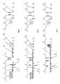
- Figure 1 is a schematic view of cutting steel strip head in the method for welding guiding strips for a stainless steel coil according to an example of the present invention.
- Figure 2 is a schematic view of welding the guiding strip for the steel strip head in the method for welding guiding strips for a stainless steel coil according to an example of the present invention.
- Figure 3 is a schematic view of winding the steel strip with the stainless steel guiding strip welded thereto in the method for welding guiding strips for a stainless steel coil according to an example of the present invention.
- Figure 4 is a schematic view of cutting the tail end of the stainless steel strip in the method for welding guiding strips for a stainless steel coil according to an example of the present invention.
- Figure 5 is a schematic view of conveying a steel coil in the method for welding guiding strips for a stainless steel coil according to an example of the present invention.
- Figure 6 is a schematic view of unwinding the stainless steel coil by the uncoiler in the method for welding guiding strips for a stainless steel coil according to an example of the present invention.
- Figure 7 is a schematic view of welding the guiding strip for the steel strip tail in the method for welding guiding strips for a stainless steel coil according to an example of the present invention.
- Figure 8 is a schematic view of winding the steel coil by the uncoiler in the method for welding guiding strips for a stainless steel coil according to an example of the present invention.
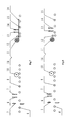
- Figure 9 is a reference top view showing the main devices and associated devices in the method for welding guiding strips for a stainless steel coil according to an example of the present invention.
- Figure 10 is a reference side view, with underground parts sectioned, showing the main devices and associated devices in the method for welding guiding strips for a stainless steel coil according to an example of the present invention.
- the reference symbols in the above figures are:
- the example of the present invention provides a system for welding guiding strips for a stainless steel coil, which comprises a preparation assembling set consisted of an uncoiler and a first welding machine, wherein the uncoiler unwinds the outer circle of the steel coil, the first welding machine welds a guiding strip for the outer circle, and the uncoiler rewinds so as to wind the guiding strip for the outer circle together with the steel coil after welding, which further comprises:
- a second welding machine provided at the end of an annealing and pickling line for a raw material, for welding a guiding strip for the head to the steel coil;
- a coiler for introducing the guiding strip for the head and winding the steel strip with the guiding strip for the head welded thereto into a steel coil
- a conveying apparatus for conveying the steel coil to the uncoiler.
- the system may further include an edge digging machine. After the welding of the second welding machine, the edge digging machine is used for performing the edge digging treatment to the welding seam between the steel strip and the guiding strip for the head.
- the system according to the example of the present invention has the features as follows:
- the example provides a method of welding on a steel strip, 1500 mm in width, 260 m in length and 8 mm in thickness, spreaded from a heat treated 0Cr18Ni9 steel coil, which comprises the steps as follows:
- the stainless steel strip 2 passes through a looper 1 to the carrier platform 4 at the outlet of the annealing and pickling line for a raw material, a length of 200 mm is cut away with a parallel-blade cutter 3 at the steel strip head 5 of the uncoiled stainless steel strip 2 which is spreaded, so that the width of the steel strip head after cutting is the same with that of the steel strip base material for the purpose of facilitating welding;
- the front end of the guiding strip 9, i.e. the left end in the figure, is aligned with the cutting edge of the steel strip head of the stainless steel strip 2, and the stainless steel guiding strip 9 is welded to the cutting edge of the steel strip head of the stainless steel strip 2 by a welding machine 6 which comprising an edge digging machine 7;
- a liftable steel coil car 18 is provided to convey the stainless steel coil 16 with a guiding strip welded thereto to a uncoiler 11 in a simple preparation assembling set;
- the stainless steel coil 16 is loaded onto the rotating uncoiler 11, the outer circle of the stainless steel coil 16, i.e. the tail of the stainless steel strip, is unwound so that a length of 15 m in the outer circle is spreaded and then the spreaded stainless steel strip is straightened by a straight head straightening machine 12 so as to make it flat;
- the uncoiler 11 is actuated to make the uncoiler 11 rotate reversely, so that the steel strip head of the stainless steel coil 16 together with the stainless steel guiding strip 19 welded thereto are wound together.
- the looper at the end of the annealing and pickling line for a raw material may be increased so as to increase the steel strip storage amount of 5-6 minutes with the length of 160 m-210 m (generally, about 200 m). For this reason, it is possible to provide a looper with two layers, and add a tension control system comprising a looper car, a hoist system and corresponding tension rollers, and perform the synchronous control by adopting two looper cars simultaneously.
- an edge digging machine matched with the welding machine at the end of the annealing and pickling line for a raw material is provided, and an edge digging machine matched with the welding machine in the simple preparation assembling set is also provided.
- a steel coil storage saddle may be provided between the annealing and pickling line for a raw material and the simple preparation assembling set as a buffing position to adapt the rhythm of the simple preparation assembling set according to the capacity of the annealing and pickling line for a raw material and the rhythm of coil striping in welding the guiding strip.
- the materials of the guiding strip 9 and the guiding strip 19 are galvanized carbon steel plate.
- the material of the stainless steel coil and the welding steps in this example are the same with those in the example 1.
- the materials of the guiding strip 9 and the guiding strip 19 are 15Cr alloy steel plate.
- the material of the stainless steel coil and the welding steps in this example are the same with those in the example 1.
- the simple preparation assembling set in the present invention mainly comprises an uncoiler, a straightening machine, an edge digging machine and a welding machine.
- the uncoiler in the present invention can rewind so as to wind the steel strip, therefore it does not need to uncoil the entire steel coil completely and it does not need to provide a coiler here.
- the existing preparation assembling set which can realize the welding of guiding strips at both ends of the stainless steel coil, mainly comprises an uncoiler, a straightening machine, an edge digging machine, a welding machine and a coiler.
- the coiler 24 is used as a backup device.
- the present invention achieves the function of welding guiding strips at both ends of the white coil (the stainless steel coil which is treated by annealing and pickling) by means of adding a welding machine at the end of the annealing and pickling line for a raw material, which is used for the welding of the guiding strip for the steel strip head, and adding a simple preparation assembling set matched with the annealing and pickling line for a raw material, which is used for the welding of the guiding strip for the steel strip tail.
- the present invention solves the problems caused by the existing methods commonly used for welding the guiding strips, such as the influence to the production capacity of the annealing and pickling line for a raw material; the difficulties in the force control in the annealing and pickling line for a raw material, especially the tension control in the furnace, which may cause the problem of strip breakage inside the furnace; and the surface damage due to one more time entire coil uncoiling for welding the guiding strip.
- the devices as follows can be used.
- the methods in the examples of the present invention are not limited to use these devices, and other devices with the same functions can also be used.
- Cutter made by Taiyuan Heavy Machinery Group Co., Ltd.
- Main components hydraulic driving members, cutting blades, electrical sensing control components;
- Function cutting the steel strip along the lateral direction, also other cutters with the corresponding functions can be used.
- Coiler made by Taiyuan Heavy Machinery Group Co., Ltd.
- Main components motor, drum, hydraulic driving members, electrical sensing control components;
- Function coiling, also other coilers with the corresponding functions can be used.
- Uncoiler made by Taiyuan Heavy Machinery Group Co., Ltd.
- Main components motor, drum, hydraulic driving members, electrical sensing control components; Function: uncoiling and rewinding the portion of the steel strip to the steel coil.
- Welding machine made by Oxytechnik of Germany Model: KONTINUMAT 2000/250/3-B MIG/MAG KONTI-D
- Main components welding gun, electrical sensing control components; Function: welding the stainless steel strip and the guiding strip;
- other welding machines or individual welding machine separated from the edge digging machine with the corresponding functions can be used.
- Edge digging machine Made by Oxytechnik of GERMERY, integrated with the welding machine Main components: hydraulic driving members, cutting blade, electrical sensing control components; Function: digging out the unwelded portion at the welding seam; In the examples of the present invention, other edge digging machines or individual edge digging machine separated from the welding machine with the corresponding functions can be used.
- Straightening machine made by Taiyuan Heavy Machinery Group Co., Ltd.
- Main components straightening roller, electrical sensing control components, hydraulic driving members; Function: straightening the steel strip to make it flat.
- the present invention realizes the function of welding guiding strips at both ends of a white coil by means of the common devices of the cutter, the coiler, the uncoiler, the straightening machine, the edge digging machine and the welding machine by effective linking and matching in rhythm with the annealing and pickling line for a raw material and providing the corresponding functions of edge digging.
Landscapes
- Engineering & Computer Science (AREA)
- Mechanical Engineering (AREA)
- Winding, Rewinding, Material Storage Devices (AREA)
Applications Claiming Priority (2)
| Application Number | Priority Date | Filing Date | Title |
|---|---|---|---|
| CNB200710061655XA CN100493824C (zh) | 2007-03-28 | 2007-03-28 | 一种不锈钢卷焊接引带的方法 |
| PCT/CN2007/071019 WO2008116367A1 (fr) | 2007-03-28 | 2007-11-05 | Procédé et système pour souder une bande guide avec une bobine d'acier inoxydable |
Publications (2)
| Publication Number | Publication Date |
|---|---|
| EP2130620A1 true EP2130620A1 (fr) | 2009-12-09 |
| EP2130620A4 EP2130620A4 (fr) | 2014-09-03 |
Family
ID=38743074
Family Applications (1)
| Application Number | Title | Priority Date | Filing Date |
|---|---|---|---|
| EP07817210.3A Withdrawn EP2130620A4 (fr) | 2007-03-28 | 2007-11-05 | Procédé et système pour souder une bande guide avec une bobine d'acier inoxydable |
Country Status (3)
| Country | Link |
|---|---|
| EP (1) | EP2130620A4 (fr) |
| CN (1) | CN100493824C (fr) |
| WO (1) | WO2008116367A1 (fr) |
Cited By (5)
| Publication number | Priority date | Publication date | Assignee | Title |
|---|---|---|---|---|
| CN102601616A (zh) * | 2012-03-22 | 2012-07-25 | 江苏中港冶金设备科技有限公司 | 一种剪切对齐机构 |
| CN103252346A (zh) * | 2012-02-17 | 2013-08-21 | 宝山钢铁股份有限公司 | 一种提高动态变规格轧制稳定性的通板方法 |
| CN111185770A (zh) * | 2020-01-11 | 2020-05-22 | 周海英 | 一种钢带及其加工装置与加工方法 |
| WO2020109851A1 (fr) * | 2018-11-30 | 2020-06-04 | Arcelormittal | Procédé de fabrication d'acier martensitique et acier martensitique ainsi obtenu |
| RU2787760C2 (ru) * | 2018-11-30 | 2023-01-12 | Арселормиттал | Способ получения мартенситной стали и соответствующая мартенситная сталь |
Families Citing this family (17)
| Publication number | Priority date | Publication date | Assignee | Title |
|---|---|---|---|---|
| CN102806423B (zh) * | 2011-05-30 | 2014-08-20 | 宝山钢铁股份有限公司 | 一种无取向硅钢激光填丝焊接方法 |
| CN102335822B (zh) * | 2011-10-17 | 2013-05-08 | 无锡市南方电器制造有限公司 | 重型焊接h型钢生产线 |
| CN102527717A (zh) * | 2012-01-06 | 2012-07-04 | 无锡华精新型材料有限公司 | 一种提高取向硅钢带冷轧成材率的冷轧方法 |
| CN105178621A (zh) | 2015-08-14 | 2015-12-23 | 诸暨市茜娜施袜业有限公司 | 使用导向杆且可调速的室外钢结构件的清洗维护装置 |
| CN105463351A (zh) * | 2015-12-31 | 2016-04-06 | 中铝西南铝冷连轧板带有限公司 | 减少铝材退火缺陷的方法 |
| CN106391724B (zh) * | 2016-11-08 | 2019-02-05 | 广西梧州市金海不锈钢有限公司 | 一种自动可逆冷轧轧制力控制装置及控制方法 |
| CN111085758A (zh) * | 2018-10-24 | 2020-05-01 | 中建材创新科技研究院有限公司 | 一种自动焊接装置 |
| CN111085818A (zh) * | 2018-10-24 | 2020-05-01 | 中建材创新科技研究院有限公司 | 一种钢带自动加工方法 |
| CN110102571B (zh) * | 2019-04-09 | 2024-08-30 | 中国重型机械研究院股份公司 | 一种不锈钢带辅助生产系统及方法 |
| CN110202378B (zh) * | 2019-07-16 | 2019-12-24 | 珠海市精实测控技术有限公司 | 一种钢带自动输送缠绕焊接机构 |
| CN113073191B (zh) * | 2020-01-04 | 2022-05-10 | 上海梅山钢铁股份有限公司 | 一种立式连续退火炉返回卷平稳过渡控制方法 |
| CN113751513B (zh) * | 2020-06-05 | 2024-09-06 | 上海梅山钢铁股份有限公司 | 一种拉矫机断带快速恢复生产的方法 |
| CN112267008B (zh) * | 2020-09-30 | 2022-02-11 | 山西太钢不锈钢股份有限公司 | 宽钢带铁铬铝合金热卷连续退火酸洗的制造方法 |
| CN112589467B (zh) * | 2020-12-27 | 2021-11-19 | 山东盛阳金属科技股份有限公司 | 一种酸洗钛板焊接装置及其焊接工艺 |
| CN113025934B (zh) * | 2021-02-20 | 2022-06-28 | 河钢股份有限公司承德分公司 | 带钢镀锌装置及方法 |
| CN114871395B (zh) * | 2022-04-20 | 2024-04-02 | 河北敬业高品钢科技有限公司 | 薄带连铸中设备参数的控制方法及装置 |
| CN119114669A (zh) * | 2024-08-26 | 2024-12-13 | 洛阳爱科麦钨钼科技股份有限公司 | 一种宽幅钼带材制备方法 |
Family Cites Families (8)
| Publication number | Priority date | Publication date | Assignee | Title |
|---|---|---|---|---|
| JPS63220902A (ja) * | 1987-03-10 | 1988-09-14 | Nkk Corp | 高珪素鋼板の温間圧延方法 |
| JPH04172105A (ja) * | 1990-11-05 | 1992-06-19 | Hitachi Ltd | 熱間極薄ストリップの圧延方法 |
| US5197179A (en) * | 1991-04-18 | 1993-03-30 | T. Sendzimir, Inc. | Means and a method of improving the quality of cold rolled stainless steel strip |
| JPH05269526A (ja) * | 1992-03-24 | 1993-10-19 | Kawasaki Steel Corp | リーダーストリップの溶接方法およびその装置 |
| JP2692527B2 (ja) * | 1993-03-29 | 1997-12-17 | 住友金属工業株式会社 | リーダストリップ付コイルの製造方法およびその設備 |
| JP2730454B2 (ja) * | 1993-06-28 | 1998-03-25 | 住友金属工業株式会社 | リーダーストリップ付コイルの製造方法およびリーダーストリップ接合設備 |
| CN1144629C (zh) * | 1999-11-29 | 2004-04-07 | 川崎制铁株式会社 | 可逆式冷轧设备 |
| KR20040056327A (ko) * | 2002-12-23 | 2004-06-30 | 주식회사 포스코 | 스테인레스용 냉간압연기 |
-
2007
- 2007-03-28 CN CNB200710061655XA patent/CN100493824C/zh active Active
- 2007-11-05 EP EP07817210.3A patent/EP2130620A4/fr not_active Withdrawn
- 2007-11-05 WO PCT/CN2007/071019 patent/WO2008116367A1/fr not_active Ceased
Cited By (12)
| Publication number | Priority date | Publication date | Assignee | Title |
|---|---|---|---|---|
| CN103252346A (zh) * | 2012-02-17 | 2013-08-21 | 宝山钢铁股份有限公司 | 一种提高动态变规格轧制稳定性的通板方法 |
| CN103252346B (zh) * | 2012-02-17 | 2015-07-22 | 宝山钢铁股份有限公司 | 一种提高动态变规格轧制稳定性的通板方法 |
| CN102601616A (zh) * | 2012-03-22 | 2012-07-25 | 江苏中港冶金设备科技有限公司 | 一种剪切对齐机构 |
| CN102601616B (zh) * | 2012-03-22 | 2014-04-09 | 江苏中港冶金设备科技有限公司 | 一种剪切对齐机构 |
| WO2020109851A1 (fr) * | 2018-11-30 | 2020-06-04 | Arcelormittal | Procédé de fabrication d'acier martensitique et acier martensitique ainsi obtenu |
| WO2020109918A1 (fr) * | 2018-11-30 | 2020-06-04 | Arcelormittal | Procédé de fabrication d'acier martensitique et acier martensitique ainsi obtenu |
| US20210404032A1 (en) * | 2018-11-30 | 2021-12-30 | Arcelormittal | A method of manufacturing martensitic steel and a martensitic steel thereof |
| JP2022513664A (ja) * | 2018-11-30 | 2022-02-09 | アルセロールミタル | マルテンサイト鋼の製造方法及びそのマルテンサイト鋼 |
| RU2787760C2 (ru) * | 2018-11-30 | 2023-01-12 | Арселормиттал | Способ получения мартенситной стали и соответствующая мартенситная сталь |
| US12157925B2 (en) * | 2018-11-30 | 2024-12-03 | Arcelormittal | Method of manufacturing Martensitic steel and a Martensitic steel thereof |
| CN111185770A (zh) * | 2020-01-11 | 2020-05-22 | 周海英 | 一种钢带及其加工装置与加工方法 |
| CN111185770B (zh) * | 2020-01-11 | 2021-06-25 | 玉环市几偶孵化器有限公司 | 一种钢带及其加工装置与加工方法 |
Also Published As
| Publication number | Publication date |
|---|---|
| EP2130620A4 (fr) | 2014-09-03 |
| WO2008116367A1 (fr) | 2008-10-02 |
| CN101024267A (zh) | 2007-08-29 |
| CN100493824C (zh) | 2009-06-03 |
Similar Documents
| Publication | Publication Date | Title |
|---|---|---|
| EP2130620A1 (fr) | Procédé et système pour souder une bande guide avec une bobine d'acier inoxydable | |
| JP4413984B2 (ja) | 冷間圧延材製造設備および冷間圧延方法 | |
| US3835681A (en) | Continuous rolling mill | |
| CN110355206B (zh) | 一种提高可逆轧机成材率的装置及生产方法 | |
| KR102172555B1 (ko) | 스테인리스 스틸의 스케일 제거방법 | |
| US4123011A (en) | Coil unwind and wind-up method and apparatus therefor | |
| CN102612414A (zh) | 冷轧材料制造设备及冷轧方法 | |
| CN103341490B (zh) | 一种卷芯和废次品钢卷整合利用生产线及工艺 | |
| EP3006122A1 (fr) | Décapage combiné et installation de laminage pour le décapage et le laminage de bandes métalliques | |
| CN103084413A (zh) | 一种廿辊机组牵引钢卷的引带导入法 | |
| US3700157A (en) | Apparatus for feeding strip-like material to a processing apparatus | |
| CN202845435U (zh) | 一种可提高不锈钢成材率的卷扬设备 | |
| CN217369753U (zh) | 一种冷轧带钢生产机组 | |
| CN114618882B (zh) | 一种冷轧带钢生产机组及生产工艺 | |
| US3365144A (en) | Method of and apparatus for continuously feeding coils of strip-like material to a processing line | |
| CN1303747A (zh) | 可逆式冷轧设备 | |
| KR101464159B1 (ko) | 스트립형 압연 스톡, 특히 금속 스트립의 압연 방법 | |
| EP3208005B1 (fr) | Installation combinée de soudage et de laminage de bandes métalliques | |
| JP3387393B2 (ja) | 連続処理ラインの能率向上方法及び装置 | |
| CN114682651A (zh) | 薄带铸轧高强钢拉矫生产线及拉矫工艺 | |
| JP2916491B2 (ja) | 被処理帯鋼板のオフゲージ部インライン処理方法 | |
| CN116351879A (zh) | 一种单机架可逆轧机断带处理方法 | |
| US3421352A (en) | Method of and apparatus for rebending strip-like material | |
| JPS5825521B2 (ja) | ストリップ処理装置におけるストリップの半連続化操作装置 | |
| JPH07330196A (ja) | 金属帯の冷間圧延装置および方法ならびに先端移送台車 |
Legal Events
| Date | Code | Title | Description |
|---|---|---|---|
| PUAI | Public reference made under article 153(3) epc to a published international application that has entered the european phase |
Free format text: ORIGINAL CODE: 0009012 |
|
| 17P | Request for examination filed |
Effective date: 20090828 |
|
| AK | Designated contracting states |
Kind code of ref document: A1 Designated state(s): AT BE BG CH CY CZ DE DK EE ES FI FR GB GR HU IE IS IT LI LT LU LV MC MT NL PL PT RO SE SI SK TR |
|
| DAX | Request for extension of the european patent (deleted) | ||
| A4 | Supplementary search report drawn up and despatched |
Effective date: 20140806 |
|
| RIC1 | Information provided on ipc code assigned before grant |
Ipc: B21B 1/36 20060101AFI20140731BHEP Ipc: B21B 3/00 20060101ALI20140731BHEP Ipc: B21C 47/26 20060101ALI20140731BHEP |
|
| STAA | Information on the status of an ep patent application or granted ep patent |
Free format text: STATUS: THE APPLICATION IS DEEMED TO BE WITHDRAWN |
|
| 18D | Application deemed to be withdrawn |
Effective date: 20160601 |