EP2140200B1 - Verbesserter gasbrenner für kochgeräte - Google Patents
Verbesserter gasbrenner für kochgeräte Download PDFInfo
- Publication number
- EP2140200B1 EP2140200B1 EP08717891.9A EP08717891A EP2140200B1 EP 2140200 B1 EP2140200 B1 EP 2140200B1 EP 08717891 A EP08717891 A EP 08717891A EP 2140200 B1 EP2140200 B1 EP 2140200B1
- Authority
- EP
- European Patent Office
- Prior art keywords
- burner
- cavity
- injectors
- burner according
- primary air
- Prior art date
- Legal status (The legal status is an assumption and is not a legal conclusion. Google has not performed a legal analysis and makes no representation as to the accuracy of the status listed.)
- Active
Links
Images


Classifications
-
- F—MECHANICAL ENGINEERING; LIGHTING; HEATING; WEAPONS; BLASTING
- F23—COMBUSTION APPARATUS; COMBUSTION PROCESSES
- F23D—BURNERS
- F23D14/00—Burners for combustion of a gas, e.g. of a gas stored under pressure as a liquid
- F23D14/02—Premix gas burners, i.e. in which gaseous fuel is mixed with combustion air upstream of the combustion zone
- F23D14/04—Premix gas burners, i.e. in which gaseous fuel is mixed with combustion air upstream of the combustion zone induction type, e.g. Bunsen burner
- F23D14/06—Premix gas burners, i.e. in which gaseous fuel is mixed with combustion air upstream of the combustion zone induction type, e.g. Bunsen burner with radial outlets at the burner head
- F23D14/065—Premix gas burners, i.e. in which gaseous fuel is mixed with combustion air upstream of the combustion zone induction type, e.g. Bunsen burner with radial outlets at the burner head with injector axis inclined to the burner head axis
-
- F—MECHANICAL ENGINEERING; LIGHTING; HEATING; WEAPONS; BLASTING
- F23—COMBUSTION APPARATUS; COMBUSTION PROCESSES
- F23D—BURNERS
- F23D2900/00—Special features of, or arrangements for burners using fluid fuels or solid fuels suspended in a carrier gas
- F23D2900/14—Special features of gas burners
- F23D2900/14062—Special features of gas burners for cooking ranges having multiple flame rings
-
- F—MECHANICAL ENGINEERING; LIGHTING; HEATING; WEAPONS; BLASTING
- F23—COMBUSTION APPARATUS; COMBUSTION PROCESSES
- F23D—BURNERS
- F23D2900/00—Special features of, or arrangements for burners using fluid fuels or solid fuels suspended in a carrier gas
- F23D2900/14—Special features of gas burners
- F23D2900/14063—Special features of gas burners for cooking ranges having one flame ring fed by multiple venturis
Definitions
- the present invention relates to an improved gas burner for cooking appliances.
- Standard gas burners comprising a single flame ring of various dimensions and developable powers.
- Special gas burners are also known comprising several concentric flame rings. They are commonly known as wok burners, from the name of the convex-based pans which are widespread in Asiatic countries, and require burners with several concentric rings.
- Dual wok burners are also known, provided with special two-way valves for separately feeding the central flame ring and the annular ring or rings with gas, to hence generate either only the inner central flame ring or the central ring and the outer annular ring or rings, in order to vary the cooking intensity within wide limits, from just the inner flame ring fed at minimum level to all the flame rings fed at maximum level for high temperature cooking.
- IT 1,232,887 describes a dual burner provided with three injectors associated with three Venturis of radial type, i.e. comprising a first vertical frusto-conical section followed by a radial horizontal section. This is of small vertical size, is able to provide reasonable power and uses primary air and secondary air withdrawn from above the hob, hence being substantially insensitive to the streaming effect.
- the drawback of this known burner is that the two radial venturis which feed mixture to the outer portion of the burner determine its shape: in this respect, to obtain a radial portion the two venturis are made to extend towards the burner interior, so giving the outer burner portion a shape which is not annular, as is normally required for a wok burner, but presenting a circular outer perimeter and an elliptical inner perimeter.
- WO2006005428 describes a burner with two horizontal parallel venturis feeding both central and external concentric burners.
- US 5,842,849 describes a burner with a cup support closed at its base, on which the injectors associated with the vertical venturis are positioned.
- the burner withdraws primary air from above the hob, however as the burner is of reduced height in order to be able to be housed within the hobs, its venturis are too short and hence of low efficiency.
- EP 1 120 603 describes a burner with a vertical venturi feeding an inner central burner and a diametrical venturi feeding an outer annular burner.
- the power developed by this burner is fairly limited; moreover the burner is formed from a very large number of parts and finally, as the two gas inlets feeding the two separate nozzles cannot be connected together, the burner operates only as a dual burner and is unable to function as a single-command burner.
- EP 1 042 634 describes a burner with two injectors feeding a vertical venturi for an inner central flame ring and a horizontal venturi for an outer annular flame ring.
- the primary air for the vertical venturi is withdrawn from above the hob, whereas the primary air for the horizontal venturi is withdrawn from below the hob.
- the injector holder for the vertical venturi is positioned above the horizontal venturi, the axial length of the vertical venturi is too small and does not enable the burner to develop the required power.
- An object of the invention is to overcome all the limitations which are recognizable conjointly or separately in burners pertaining to the state of the art, by providing a burner which satisfies all the aforelisted requirements.
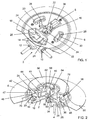
- Figures 1 to 5 show the burner of the invention in the dual version, comprising a cup-shaped support 3 formed from two superposed parts 2 and 4, which are coupled together and fixed to the upper sheet metal 6 of the hob by screws 8.
- Two gas inlets 10 and 12 are provided at a vertical wall of the upper part 4 of the cup-shaped support 3.
- the inlet 10 communicates with a pair of spaced-apart nozzles 14 of horizontal axis, whereas the inlet 12 communicates with a nozzle of vertical axis positioned at the centre of the cup-shaped support 3.
- the two horizontal nozzles 14 terminate at an upperly open cavity 18 defined by a rim emerging from the sheet metal 6 of the cooking hob.
- this rim which forms all the side walls of the cavity 18, comprises a lesser projecting portion 20 of the cavity wall, to which the nozzles 14 are applied, and a greater projecting portion 22 involving the other three walls.
- Two parallel venturi conduits 24 of horizontal axis extend from that wall of the cavity 18 opposite the wall to which the nozzles 14 are applied. These venturis extend from the cavity 18, they are spaced apart and, after passing through virtually the entire cup-shaped support 3, open into an arcuate channel 26 which extends as two branches, themselves extending upperly into two vertical channels 28 which pass through the sheet metal 6 of the hob and are each provided with a rim 30 projecting upwards to an extent equal to the rim 22 of the cavity 18.
- the two horizontal venturis 24 extend spaced apart to define a space within which the nozzle 16 of vertical axis is positioned. It is housed in a cavity 32 defined by side walls which emerge via their upper rim from the sheet metal 6 of the hob.
- This upper rim comprises a portion 34 joined to the greater projecting rim 22 of the cavity 18 and having the same height thereas, and a portion 36 more distant from the cavity 18 and depressed to an extent substantially equal to the rim 20 thereof.
- the burner body 38 is positioned on the top portion 4 of the cup-shaped support 3. It comprises an inner cylindrical portion 40 and an outer annular portion 42 joined together by a substantially horizontal flange 44.
- the outer annular portion 42 is provided with a base 46 in which two apertures are provided in positions corresponding with the vertical channels 28 of the cup-shaped support 3, so that when the burner body 38 is positioned on said cup-shaped support, there is communication continuity between the channel 26 and the annular cavity 47 of the portion 42.
- the outer wall of the annular cavity 47 of the portion 42 is provided with a plurality of ports 48 for emergence of the gas-primary air mixture.
- a vertical venturi conduit 50 is provided in the inner cylindrical portion 40 of the burner 38 and upperly faces the nozzle 16 of vertical axis. It opens upperly into a circular chamber 52, the outer wall of which comprises a plurality of ports 54.
- the annular chamber 47 is closed upperly by a removable angular cover 56, while the circular chamber 52 is closed upperly by a circular cover 58.
- the burner 38 rests on the cup-shaped support 3 at the greater projecting rims 22, 30 and 34 thereof, and remains centered in the correct mutual position by the engagement of its appendices 38, projecting downwards from the central portion 40 of the burner 38 and cooperating with the cavity 32 of the cup-shaped support 3. At the peripheral edge of its annular portion 42 it remains spaced from the sheet metal of the cooking hob, to hence define a passage for entry of the primary air which has to reach the two cavities 18 and 32.
- the annular portion 42 of the burner 38 presents a channel 62, the side walls 64 of which present small slits 66.
- the aforedescribed burner operates in the following manner.
- Gas leaving through the vertical nozzle 16 and through the two spaced-apart horizontal nozzles 14 can be regulated in the required manner by a two-exit dual valve.
- the gas flow leaving the vertical nozzle 16 entrains into the cavity 32 a flow of primary air originating from the top of the hob 6 via a first passage defined lowerly by this latter and upperly by the outer edge of the burner 38, and then via a second passage defined lowerly by the depressed rim 36 of the cavity 32 and upperly by the burner 38.
- the path of the primary air is indicated by the arrow 68 in Figure 5 .
- the gas mixes with the primary air, the formed mixture then reaching the circular cavity 52, from which it can leave towards the ports 54.
- the secondary air flow path for the central burner 40 is indicated by the arrow 74 in Figure 5 .
- the gas flow leaving the two nozzles 14 entrains into the cavity 18 another flow of primary air originating from the top of the hob 6 via a first passage defined lowerly by this latter and upperly by the outer edge of the burner 38, and then via a second passage defined lowerly by the depressed rim 20 of the cavity 18 and upperly by the burner 38.
- the gas mixes with the primary air, the formed mixture passing through the two branches of the arcuate channel 26 and the two vertical channels 28 to reach the annular cavity 42, from which it can leave towards the ports 48, to give rise to the outer flame ring 78, fed by secondary air originating from above the hob 6, as indicate by the arrow 80 in Figure 2 .
- the dual valve is arranged to feed only the central nozzle 16 with gas, only the inner flame ring 72 will be fed. If the valve is then made to also feed the horizontal nozzles 14, the slits 66 give rise to flames which enable mixture ignition to be transmitted by the flames 72 to the flames 78.
- one of the two gas inlets is closed by a plug 88, while the other, fed by a single-exit valve, feeds both the two horizontal nozzles 14 and the vertical nozzle 16.
- the burner operates with the flame rings fed simultaneously, as in the case of traditional burners.
- the chamber 18 comprises apertures 82 in its base and is closed upperly by a cover 84 fixed by screws.
- This solution is also more advantageous than the preceding one with regard to the primary air volume which can be drawn in, and hence the greater power which the burner can develop.
- it is insensitive to the streaming effect in that, even if on opening and/or closing the ports below the hob the outer portion is extinguished, the inner portion, being fed by primary air originating from above the hob, continues to operate and is able to immediately re-ignite said outer portion.
- wall of the chamber 18 to which the nozzles 14 are applied is provided with an aperture positioned below the sheet metal 6 of the hob.
Landscapes
- Engineering & Computer Science (AREA)
- Chemical & Material Sciences (AREA)
- Combustion & Propulsion (AREA)
- Mechanical Engineering (AREA)
- General Engineering & Computer Science (AREA)
- Gas Burners (AREA)
Claims (17)
- Gasbrenner für Kochgeräte, mit einer becherförmigen Halterung (3), die mit dem Blech (6) eines Kochherds verbunden werden kann, mit einem Paar benachbarter Venturi-Rohre (24) mit im Wesentlichen horizontalen parallelen Achsen, die in der becherförmigen Halterung (3) aufgenommen sind und bezüglich einer diametralen vertikalen Ebene des Brenners symmetrisch angeordnet sind, mit ersten Einspritzeinrichtungen (14), die mit den benachbarten Venturi-Rohren (24) in Zusammenhang stehen und selbst im Wesentlichen horizontale Achsen aufweisen, und mit einem Brennerkörper (38), der auf der becherförmigen Halterung (3) platziert ist und einen mittigen Innenabschnitt (40), der eine Innenkammer (52) definiert, die mit einem mittigen Flammenring (72) ausgestattet ist, und einen Außenabschnitt (42) aufweist, der zum mittigen Abschnitt (40) konzentrisch ist, und eine Außenkammer (47) definiert, die mit wenigstens einem äußeren Flammenring (78) ausgestattet ist, wobei die benachbarten Venturi-Rohre (24) dem Außenabschnitt (42) ein Gemisch aus Gas und Primärluft zur Erzeugung des äußeren Flammenrings (78) zuführen, wobei die ersten Einspritzeinrichtungen (14) an der Wand eines ersten Hohlraums (18) befestigt sind, der in der becherförmigen Halterung (3) aufgenommen ist und von dem sich die benachbarten horizontalen Venturi-Rohre (24) erstrecken, wobei der Hohlraum offen und von oben zugänglich ist,
dadurch gekennzeichnet, dass:- die benachbarten horizontalen Venturi-Rohre (24) im Abstand voneinander angeordnet sind und einen Raum definieren, in dem ein zweiter Hohlraum (32) aufgenommen ist, mit einer zweiten Einspritzeinrichtung (16) mit einer an seiner Basis fixierten vertikalen Achse, zu einem Venturi-Rohr (50) ebenfalls mit vertikaler Achse weisend, das in dem Brennerkörper (38) aufgenommen ist und dem mittigen Innenabschnitt (40) ein Gemisch aus Gas und Primärluft zur Erzeugung des mittigen Flammenrings (72) zuführt,- der zweite Hohlraum (32) nach oben offen ist und mit dem Raum außerhalb des Brenners über dem Kochherd verbunden werden kann. - Brenner nach Anspruch 1, dadurch gekennzeichnet, dass der erste Hohlraum (18), in dem die ersten Einspritzeinrichtungen (14) angelegt werden, ausschließlich mit dem Raum außerhalb des Brenners über dem Kochherd in Verbindung stehen kann.
- Brenner nach Anspruch 1, dadurch gekennzeichnet, dass der erste Hohlraum (18), in dem die ersten Einspritzeinrichtungen (14) angelegt werden, ausschließlich mit dem Raum außerhalb des Brenners unter dem Kochherd in Verbindung stehen kann.
- Brenner nach Anspruch 1, dadurch gekennzeichnet, dass der erste Hohlraum (18), in dem die ersten Einspritzeinrichtungen (14) angelegt werden, sowohl mit dem Raum außerhalb des Brenners über dem Kochherd als auch mit dem Raum außerhalb des Brenners unter dem Kochherd in Verbindung stehen kann.
- Brenner nach Anspruch 1, dadurch gekennzeichnet, dass der mittige Abschnitt (40) und der äußere Abschnitt (42) durch einen ringförmigen Zwischenraum voneinander getrennt sind, der über einen ringförmigen Durchgang, der unten von dem Blech (6) des Kochherds und oben von dem äußeren Abschnitt (42) des Brennerkörpers (38) definiert wird, mit der Außenseite des Brennerkörpers in Verbindung stehen kann.
- Brenner nach Anspruch 1, dadurch gekennzeichnet, dass sich die benachbarten Venturi-Rohre (24) von dem ersten Hohlraum (18) erstrecken und in einen bogenförmigen Kanal (26) in Fluidverbindung mit der Außenkammer (47) münden.
- Brenner nach Anspruch 6, dadurch gekennzeichnet, dass sich der bogenförmige Kanal (26) von der Region, in der die Enden der benachbarten Venturi-Rohre (24) offen sind, als zwei Zweige erstreckt, die sich an ihren Enden in vertikale Kanäle (28) erstrecken, die mit der Außenkammer (47) über entsprechende Öffnungen in der Basis (46) letzterer in Verbindung stehen.
- Brenner nach Anspruch 1, dadurch gekennzeichnet, dass die Basis des zweiten Hohlraums (32) bezüglich der benachbarten Venturi-Rohre (24) auf einer niedrigeren Höhe angeordnet ist.
- Brenner nach Anspruch 7, dadurch gekennzeichnet, dass der Brennerkörper (38) auf der becherförmigen Halterung (3) auf den Rändern der Hohlräume (18, 32) und der oberen Öffnungen der vertikalen Kanäle (28) liegt.
- Brenner nach Anspruch 9, dadurch gekennzeichnet, dass der mittige Innenabschnitt (40) unten mit Anhängen (60) ausgestattet ist, die nach unten weisen und mit dem zweiten Hohlraum (32) zusammenarbeiten, um den Brennerkörper (38) auf der becherförmigen Halterung (3) zentriert zu halten.
- Brenner nach Anspruch 9, dadurch gekennzeichnet, dass der erste Hohlraum (18) unten geschlossen ist und wenigstens ein Teil (20) seines Rands unter dem restlichen Teil des Rands vertieft ist, um mit dem darüber liegenden Brennerkörper (38) einen Durchgang für die Primärluft, die für die ersten Einspritzeinrichtungen (14) bestimmt ist, zu definieren.
- Brenner nach Anspruch 9, dadurch gekennzeichnet, dass der zweite Hohlraum (32) unten geschlossen ist und wenigstens ein Teil (36) seines Rands unter dem restlichen Rand des Rands selbst vertieft ist, um mit dem darüber liegenden Brennerkörper (38) einen Durchgang für die Primärluft, die für die zweite Einspritzeinrichtung (16) bestimmt ist, zu definieren.
- Brenner nach den Ansprüchen 4 und 9, dadurch gekennzeichnet, dass der erste Hohlraum (18) auf seiner Basis wenigstens eine Öffnung für den Durchgang von Primärluft bereitstellt, die von unterhalb des Kochherds (6) kommt und für die ersten Einspritzeinrichtungen (14) bestimmt ist, und dass er auch wenigstens einen vertieften Teil (20) seines Rands unter dem restlichen Teil des Rands bereitstellt, um mit dem darüber liegenden Brennerkörper (38) einen Durchgang für weitere Primärluft definieren, die von oberhalb des Kochherds (6) kommt und ebenfalls für die ersten Einspritzeinrichtungen bestimmt ist.
- Brenner nach Anspruch 12, dadurch gekennzeichnet, dass der Außenabschnitt (42) des Brenners (38) in einem zum vertieften Rand (36) des zweiten Hohlraums (32) weisenden Abschnitt einen Kanal (62) bereitstellt, dessen Seitenwände (64) kleine Schlitze (66) aufweisen.
- Brenner nach Anspruch 3, dadurch gekennzeichnet, dass der erste Hohlraum (18) oben mit einer abnehmbaren Abdeckung (34) geschlossen ist und an seiner Basis mit wenigstens einer Öffnung zum Durchleiten von Primärluft für die ersten Einspritzeinrichtungen (14), die von unterhalb des Kochherds kommt, ausgestattet ist.
- Brenner nach Anspruch 1, dadurch gekennzeichnet, dass die ersten Einspritzeinrichtungen (14) und die zweite Einspritzeinrichtung (16) mit zwei separaten Gaseinlässen (10, 12) verbunden sind, die über ein Doppelventil mit zwei Ausgängen gespeist werden.
- Brenner nach Anspruch 1, dadurch gekennzeichnet, dass die ersten Einspritzeinrichtungen (14) und die zweite Einspritzeinrichtung (16) mit einem einzelnen Gaseinlass (10) verbunden sind, der über eine Ventil mit einem Ausgang gespeist wird.
Priority Applications (1)
| Application Number | Priority Date | Filing Date | Title |
|---|---|---|---|
| PL08717891T PL2140200T3 (pl) | 2007-03-23 | 2008-03-17 | Ulepszony palnik gazowy do urządzeń do gotowania |
Applications Claiming Priority (2)
| Application Number | Priority Date | Filing Date | Title |
|---|---|---|---|
| IT000018A ITVE20070018A1 (it) | 2007-03-23 | 2007-03-23 | Bruciatore perfezionato a gas per apparecchi di cottura.- |
| PCT/EP2008/053154 WO2008116773A2 (en) | 2007-03-23 | 2008-03-17 | Improved gas burner for cooking appliances |
Publications (2)
| Publication Number | Publication Date |
|---|---|
| EP2140200A2 EP2140200A2 (de) | 2010-01-06 |
| EP2140200B1 true EP2140200B1 (de) | 2016-07-20 |
Family
ID=39682534
Family Applications (1)
| Application Number | Title | Priority Date | Filing Date |
|---|---|---|---|
| EP08717891.9A Active EP2140200B1 (de) | 2007-03-23 | 2008-03-17 | Verbesserter gasbrenner für kochgeräte |
Country Status (9)
| Country | Link |
|---|---|
| US (1) | US9127838B2 (de) |
| EP (1) | EP2140200B1 (de) |
| KR (2) | KR101887258B1 (de) |
| CN (1) | CN101636618A (de) |
| BR (1) | BRPI0807852B1 (de) |
| ES (1) | ES2594866T3 (de) |
| IT (1) | ITVE20070018A1 (de) |
| PL (1) | PL2140200T3 (de) |
| WO (1) | WO2008116773A2 (de) |
Families Citing this family (40)
| Publication number | Priority date | Publication date | Assignee | Title |
|---|---|---|---|---|
| US8973569B2 (en) * | 2009-02-18 | 2015-03-10 | Electrolux Home Products, Inc. | Gas burner |
| PL2236921T3 (pl) | 2009-03-18 | 2015-04-30 | Electrolux Home Products Corp Nv | Ulepszony palnik gazowy |
| US8899972B2 (en) * | 2009-12-14 | 2014-12-02 | Electrolux Home Products, Inc. | Burner designed for wide range of input rates |
| PT2588808T (pt) * | 2010-06-30 | 2022-03-14 | Sabaf Spa | Queimador a gás com meios para prevenir a propagação de chama |
| IT1401700B1 (it) * | 2010-09-13 | 2013-08-02 | Sabaf Spa | Bruciatore a gas dotato di canali di collegamento della fiamma |
| JP5089753B2 (ja) * | 2010-10-28 | 2012-12-05 | リンナイ株式会社 | ガスバーナ |
| ITAN20120036A1 (it) | 2011-04-19 | 2012-10-20 | Somipress Societa Metalli Iniett Ati S P A | Fornello a gas con fiamma rivolta verso l'interno. |
| CN102230622B (zh) * | 2011-06-21 | 2013-04-17 | 美的集团股份有限公司 | 一种用于燃气灶具的燃烧器 |
| WO2013068775A1 (en) * | 2011-11-08 | 2013-05-16 | Sabaf S.P.A. | Gas burner |
| PL2712334T3 (pl) * | 2012-05-17 | 2017-03-31 | Sabaf S.P.A. | Sposób wytwarzania palnika gazowego |
| CN103939901A (zh) * | 2013-01-23 | 2014-07-23 | 美的集团股份有限公司 | 底杯组件、上进风燃烧器及燃气灶具 |
| CN103438453A (zh) * | 2013-07-15 | 2013-12-11 | 华中科技大学 | 一种用于燃气灶具的内喷式燃烧器 |
| CN103742909B (zh) * | 2014-01-25 | 2017-02-08 | 浙江帅丰电器有限公司 | 一种具有双引射器的上进风燃烧器 |
| NL2014954B1 (nl) * | 2014-11-28 | 2016-10-11 | Pcs Holding B V | Brandermodule voorzien van hitteschild en bus, fornuis of kookplaat voorzien daarvan en werkwijze voor het vervaardigen daarvan. |
| CN104713083B (zh) * | 2015-03-12 | 2017-05-03 | 广东美的厨房电器制造有限公司 | 燃烧器及燃气用具 |
| CN104713087B (zh) | 2015-03-12 | 2017-10-27 | 广东美的厨房电器制造有限公司 | 底杯盖及燃烧器及燃气用具 |
| CN104713089B (zh) * | 2015-03-12 | 2018-01-02 | 广东美的厨房电器制造有限公司 | 燃烧器及燃气用具 |
| CN104713084B (zh) * | 2015-03-12 | 2017-10-27 | 广东美的厨房电器制造有限公司 | 燃烧器及燃气用具 |
| CN104776433B (zh) * | 2015-03-13 | 2017-05-03 | 广东美的厨房电器制造有限公司 | 燃烧器 |
| EP3270056A4 (de) * | 2015-03-13 | 2018-10-17 | Guangdong Midea Kitchen Appliances | Brenner |
| CN107567569B (zh) * | 2015-04-24 | 2019-08-16 | 德芬迪意大利有限责任公司 | 有多环主火焰的改进煤气燃烧器 |
| ITUB20153850A1 (it) * | 2015-04-24 | 2017-03-24 | Defendi Italy Srl | Bruciatore a gas con piu corone di fiamme per piani di cottura. |
| WO2016170499A1 (en) * | 2015-04-24 | 2016-10-27 | Defendi Italy S.R.L. | Improved gas burner for cooking appliances |
| CN107667256B (zh) * | 2015-05-19 | 2019-10-18 | Somipress注射金属协会股份责任有限公司 | 双火焰冠部气体燃烧器 |
| ES2648697B1 (es) * | 2016-07-04 | 2018-10-22 | Bsh Electrodomésticos España, S.A. | Quemador de gas y aparato de cocción doméstico |
| US10393387B2 (en) | 2016-11-21 | 2019-08-27 | Haier Us Appliance Solutions, Inc. | Gas burner assembly for a cooktop appliance |
| US10330326B2 (en) | 2016-11-21 | 2019-06-25 | Haier Us Appliance Solutions, Inc. | Gas burner assembly for a cooktop appliance |
| TR201702673A2 (tr) * | 2017-02-22 | 2018-09-21 | Arcelik As | Bi̇r bek grubu |
| CN106989388A (zh) * | 2017-04-01 | 2017-07-28 | 浙江森歌电器有限公司 | 灶具燃烧器 |
| EP3775686B1 (de) * | 2018-03-30 | 2023-05-10 | Arçelik Anonim Sirketi | Gasbrennergruppe |
| CN112236619B (zh) * | 2018-06-25 | 2023-10-03 | 伊莱克斯家用电器股份公司 | 燃气燃烧器组件和包括至少一个燃气燃烧器组件的燃气烹饪器具 |
| CN109000232B (zh) * | 2018-09-04 | 2023-09-08 | 佛山市顺德区美的洗涤电器制造有限公司 | 燃烧器及燃气灶具 |
| CN109000243B (zh) * | 2018-09-04 | 2023-09-08 | 佛山市顺德区美的洗涤电器制造有限公司 | 底杯、燃烧器及燃气灶具 |
| IT201900004867A1 (it) * | 2019-04-01 | 2020-10-01 | Sabaf Spa | Bruciatore a gas |
| IT201900010935A1 (it) * | 2019-07-04 | 2021-01-04 | Ego Elektro Geraetebau Gmbh | Bruciatore a gas multicorona. |
| US11473775B2 (en) * | 2019-08-08 | 2022-10-18 | Whirlpool Corporation | Cooking appliance having a hob |
| CN112944346B (zh) * | 2021-03-31 | 2025-03-11 | 广东万和新电气股份有限公司 | 环状燃气分气结构、燃烧器装置及热水设备 |
| US11940148B2 (en) | 2021-10-28 | 2024-03-26 | Electrolux Appliances Aktiebolag | Multi injection dual ring gas burner for domestic gas cooking units |
| KR102586814B1 (ko) * | 2021-12-25 | 2023-10-06 | 문성철 | 가스버너 |
| CN116182192B (zh) * | 2023-03-09 | 2024-04-19 | 中国空气动力研究与发展中心空天技术研究所 | 一种用于燃烧加热设备的气膜冷却点火环 |
Family Cites Families (19)
| Publication number | Priority date | Publication date | Assignee | Title |
|---|---|---|---|---|
| DE4125308C2 (de) * | 1991-07-31 | 2002-06-13 | Isphording Germany Gmbh | Gasbrenner |
| GB2280743B (en) * | 1993-08-06 | 1997-03-19 | Tri Square Ind Co Ltd | Gas burner |
| GB2322696B (en) * | 1997-02-28 | 1999-01-06 | Tri Square Ind Co Ltd | Gas burner |
| IT1294585B1 (it) * | 1997-08-11 | 1999-04-12 | Defendi Srl Off Mec | Bruciatore a gas a piu' settori di fiamma. |
| EP0903538A1 (de) | 1997-09-23 | 1999-03-24 | SABAF S.p.A. | Gasbrenner |
| IT1311777B1 (it) * | 1999-01-29 | 2002-03-19 | Ohg Defendi Srl | Bruciatore a gas, particolarmente per piani di cottura ad incasso. |
| US6132205A (en) * | 2000-01-06 | 2000-10-17 | Harneit; Uwe | Multi-ring sealed gas burner |
| FR2804496B1 (fr) * | 2000-01-28 | 2002-07-19 | Sourdillon Sa | Bruleur a gaz a multiples couronnes de flammes |
| HU227511B1 (hu) * | 2002-11-12 | 2011-07-28 | Sabaf Spa | Gázégõ gáztûzhelyekhez |
| ITVE20040031A1 (it) * | 2004-07-09 | 2004-10-09 | Ohg Defendi S R L | Bruciatore a piu' settori di fiamme. |
| KR101196106B1 (ko) * | 2004-07-09 | 2012-11-01 | 디펜디 이탈리아 에스.알.엘. | 다수의 화염 섹터를 포함하는 버너 |
| US7594812B2 (en) * | 2005-01-17 | 2009-09-29 | SO. M. I Press - Societa′ Metalli Iniettati, SpA | Double burner for gas cookers, of the type provided with multiple concentric flame crowns |
| ITVE20050004A1 (it) | 2005-01-20 | 2006-07-21 | Ohg Defendi S R L | Bruciatore a gas per apparecchiature di cottura. |
| ITMC20050036A1 (it) * | 2005-04-29 | 2006-10-30 | So M I Press Societa Metalli Iniettati Spa | Doppio bruciatore per fornelli a gas, a piu' corone concentriche di fiamme, ad elevata potenza. |
| FR2889293B1 (fr) * | 2005-07-29 | 2009-12-18 | Burner Systems Int Bsi | Bruleur a gaz a multiples couronnes de flammes concentriques |
| US7661954B2 (en) * | 2005-09-13 | 2010-02-16 | Uwe Harneit | Gas burner |
| ITTO20070133A1 (it) * | 2007-02-26 | 2008-08-27 | Indesit Co Spa | Sistema di bruciatori di gas per apparecchi di cottura per alimenti |
| EP2258982B1 (de) * | 2007-10-23 | 2019-01-16 | Electrolux Home Products Corporation N.V. | Verbesserter gasbrenner |
| PL2236921T3 (pl) * | 2009-03-18 | 2015-04-30 | Electrolux Home Products Corp Nv | Ulepszony palnik gazowy |
-
2007
- 2007-03-23 IT IT000018A patent/ITVE20070018A1/it unknown
-
2008
- 2008-03-17 ES ES08717891.9T patent/ES2594866T3/es active Active
- 2008-03-17 KR KR1020157004827A patent/KR101887258B1/ko active Active
- 2008-03-17 WO PCT/EP2008/053154 patent/WO2008116773A2/en not_active Ceased
- 2008-03-17 PL PL08717891T patent/PL2140200T3/pl unknown
- 2008-03-17 CN CN200880006127A patent/CN101636618A/zh active Pending
- 2008-03-17 US US12/449,797 patent/US9127838B2/en active Active
- 2008-03-17 EP EP08717891.9A patent/EP2140200B1/de active Active
- 2008-03-17 KR KR20097016332A patent/KR20090127871A/ko not_active Ceased
- 2008-03-17 BR BRPI0807852A patent/BRPI0807852B1/pt active IP Right Grant
Also Published As
| Publication number | Publication date |
|---|---|
| BRPI0807852B1 (pt) | 2018-12-04 |
| ES2594866T3 (es) | 2016-12-23 |
| WO2008116773A3 (en) | 2009-04-16 |
| KR20090127871A (ko) | 2009-12-14 |
| EP2140200A2 (de) | 2010-01-06 |
| BRPI0807852A2 (pt) | 2014-06-17 |
| PL2140200T3 (pl) | 2017-04-28 |
| ITVE20070018A1 (it) | 2008-09-24 |
| KR20150038324A (ko) | 2015-04-08 |
| WO2008116773A2 (en) | 2008-10-02 |
| CN101636618A (zh) | 2010-01-27 |
| US20100092902A1 (en) | 2010-04-15 |
| KR101887258B1 (ko) | 2018-08-09 |
| US9127838B2 (en) | 2015-09-08 |
Similar Documents
| Publication | Publication Date | Title |
|---|---|---|
| EP2140200B1 (de) | Verbesserter gasbrenner für kochgeräte | |
| EP2572141B1 (de) | Gasbrenner mit mehreren flammenringen | |
| EP1838997B1 (de) | Gasbrenner für kochgeräte | |
| US8899972B2 (en) | Burner designed for wide range of input rates | |
| EP3268667B1 (de) | Verbesserter gasbrenner | |
| EP1781989B1 (de) | Gasbrenner mit mehreren flammenringen | |
| EP0634608A2 (de) | Doppelring-Gasbrenner | |
| EP3004737B1 (de) | Verbesserter gasbrenner | |
| MX2012014726A (es) | Quemador de gas con flama orientada hacia dentro. | |
| US11441781B2 (en) | System of gas burners, in particular for a cooking top for household use | |
| US10393386B2 (en) | System of gas burners, in particular for a cooking top for household use | |
| EP1459012B1 (de) | Gasbrenner mit mehreren flammensektoren | |
| EP3994391B1 (de) | Gasbrenner | |
| EP3591289B1 (de) | Zweikreisbrenner, gasbrenneranordnung und gasherd | |
| US11774090B2 (en) | Double-stacked gas burner | |
| CN219389729U (zh) | 一种易清洁燃烧器 | |
| EP3748230B1 (de) | Gasbrenneranordnung | |
| CN110107896B (zh) | 一种双环火灶具燃烧器 | |
| CN118423721A (zh) | 一种防爆燃的灶具燃烧器 |
Legal Events
| Date | Code | Title | Description |
|---|---|---|---|
| PUAI | Public reference made under article 153(3) epc to a published international application that has entered the european phase |
Free format text: ORIGINAL CODE: 0009012 |
|
| 17P | Request for examination filed |
Effective date: 20091012 |
|
| AK | Designated contracting states |
Kind code of ref document: A2 Designated state(s): AT BE BG CH CY CZ DE DK EE ES FI FR GB GR HR HU IE IS IT LI LT LU LV MC MT NL NO PL PT RO SE SI SK TR |
|
| DAX | Request for extension of the european patent (deleted) | ||
| 17Q | First examination report despatched |
Effective date: 20121008 |
|
| GRAC | Information related to communication of intention to grant a patent modified |
Free format text: ORIGINAL CODE: EPIDOSCIGR1 |
|
| GRAP | Despatch of communication of intention to grant a patent |
Free format text: ORIGINAL CODE: EPIDOSNIGR1 |
|
| INTG | Intention to grant announced |
Effective date: 20160401 |
|
| GRAS | Grant fee paid |
Free format text: ORIGINAL CODE: EPIDOSNIGR3 |
|
| GRAA | (expected) grant |
Free format text: ORIGINAL CODE: 0009210 |
|
| AK | Designated contracting states |
Kind code of ref document: B1 Designated state(s): AT BE BG CH CY CZ DE DK EE ES FI FR GB GR HR HU IE IS IT LI LT LU LV MC MT NL NO PL PT RO SE SI SK TR |
|
| REG | Reference to a national code |
Ref country code: GB Ref legal event code: FG4D |
|
| REG | Reference to a national code |
Ref country code: CH Ref legal event code: EP |
|
| REG | Reference to a national code |
Ref country code: IE Ref legal event code: FG4D |
|
| REG | Reference to a national code |
Ref country code: AT Ref legal event code: REF Ref document number: 814427 Country of ref document: AT Kind code of ref document: T Effective date: 20160815 |
|
| REG | Reference to a national code |
Ref country code: DE Ref legal event code: R096 Ref document number: 602008045188 Country of ref document: DE |
|
| REG | Reference to a national code |
Ref country code: LT Ref legal event code: MG4D |
|
| REG | Reference to a national code |
Ref country code: NL Ref legal event code: MP Effective date: 20160720 |
|
| REG | Reference to a national code |
Ref country code: AT Ref legal event code: MK05 Ref document number: 814427 Country of ref document: AT Kind code of ref document: T Effective date: 20160720 |
|
| REG | Reference to a national code |
Ref country code: ES Ref legal event code: FG2A Ref document number: 2594866 Country of ref document: ES Kind code of ref document: T3 Effective date: 20161223 |
|
| PG25 | Lapsed in a contracting state [announced via postgrant information from national office to epo] |
Ref country code: FI Free format text: LAPSE BECAUSE OF FAILURE TO SUBMIT A TRANSLATION OF THE DESCRIPTION OR TO PAY THE FEE WITHIN THE PRESCRIBED TIME-LIMIT Effective date: 20160720 Ref country code: HR Free format text: LAPSE BECAUSE OF FAILURE TO SUBMIT A TRANSLATION OF THE DESCRIPTION OR TO PAY THE FEE WITHIN THE PRESCRIBED TIME-LIMIT Effective date: 20160720 Ref country code: LT Free format text: LAPSE BECAUSE OF FAILURE TO SUBMIT A TRANSLATION OF THE DESCRIPTION OR TO PAY THE FEE WITHIN THE PRESCRIBED TIME-LIMIT Effective date: 20160720 Ref country code: NO Free format text: LAPSE BECAUSE OF FAILURE TO SUBMIT A TRANSLATION OF THE DESCRIPTION OR TO PAY THE FEE WITHIN THE PRESCRIBED TIME-LIMIT Effective date: 20161020 Ref country code: IS Free format text: LAPSE BECAUSE OF FAILURE TO SUBMIT A TRANSLATION OF THE DESCRIPTION OR TO PAY THE FEE WITHIN THE PRESCRIBED TIME-LIMIT Effective date: 20161120 Ref country code: NL Free format text: LAPSE BECAUSE OF FAILURE TO SUBMIT A TRANSLATION OF THE DESCRIPTION OR TO PAY THE FEE WITHIN THE PRESCRIBED TIME-LIMIT Effective date: 20160720 |
|
| REG | Reference to a national code |
Ref country code: FR Ref legal event code: PLFP Year of fee payment: 10 |
|
| PG25 | Lapsed in a contracting state [announced via postgrant information from national office to epo] |
Ref country code: GR Free format text: LAPSE BECAUSE OF FAILURE TO SUBMIT A TRANSLATION OF THE DESCRIPTION OR TO PAY THE FEE WITHIN THE PRESCRIBED TIME-LIMIT Effective date: 20161021 Ref country code: SE Free format text: LAPSE BECAUSE OF FAILURE TO SUBMIT A TRANSLATION OF THE DESCRIPTION OR TO PAY THE FEE WITHIN THE PRESCRIBED TIME-LIMIT Effective date: 20160720 Ref country code: LV Free format text: LAPSE BECAUSE OF FAILURE TO SUBMIT A TRANSLATION OF THE DESCRIPTION OR TO PAY THE FEE WITHIN THE PRESCRIBED TIME-LIMIT Effective date: 20160720 Ref country code: BE Free format text: LAPSE BECAUSE OF FAILURE TO SUBMIT A TRANSLATION OF THE DESCRIPTION OR TO PAY THE FEE WITHIN THE PRESCRIBED TIME-LIMIT Effective date: 20160720 Ref country code: AT Free format text: LAPSE BECAUSE OF FAILURE TO SUBMIT A TRANSLATION OF THE DESCRIPTION OR TO PAY THE FEE WITHIN THE PRESCRIBED TIME-LIMIT Effective date: 20160720 Ref country code: PT Free format text: LAPSE BECAUSE OF FAILURE TO SUBMIT A TRANSLATION OF THE DESCRIPTION OR TO PAY THE FEE WITHIN THE PRESCRIBED TIME-LIMIT Effective date: 20161121 |
|
| REG | Reference to a national code |
Ref country code: DE Ref legal event code: R097 Ref document number: 602008045188 Country of ref document: DE |
|
| PG25 | Lapsed in a contracting state [announced via postgrant information from national office to epo] |
Ref country code: RO Free format text: LAPSE BECAUSE OF FAILURE TO SUBMIT A TRANSLATION OF THE DESCRIPTION OR TO PAY THE FEE WITHIN THE PRESCRIBED TIME-LIMIT Effective date: 20160720 Ref country code: EE Free format text: LAPSE BECAUSE OF FAILURE TO SUBMIT A TRANSLATION OF THE DESCRIPTION OR TO PAY THE FEE WITHIN THE PRESCRIBED TIME-LIMIT Effective date: 20160720 |
|
| PLBE | No opposition filed within time limit |
Free format text: ORIGINAL CODE: 0009261 |
|
| STAA | Information on the status of an ep patent application or granted ep patent |
Free format text: STATUS: NO OPPOSITION FILED WITHIN TIME LIMIT |
|
| PG25 | Lapsed in a contracting state [announced via postgrant information from national office to epo] |
Ref country code: DK Free format text: LAPSE BECAUSE OF FAILURE TO SUBMIT A TRANSLATION OF THE DESCRIPTION OR TO PAY THE FEE WITHIN THE PRESCRIBED TIME-LIMIT Effective date: 20160720 Ref country code: BG Free format text: LAPSE BECAUSE OF FAILURE TO SUBMIT A TRANSLATION OF THE DESCRIPTION OR TO PAY THE FEE WITHIN THE PRESCRIBED TIME-LIMIT Effective date: 20161020 Ref country code: CZ Free format text: LAPSE BECAUSE OF FAILURE TO SUBMIT A TRANSLATION OF THE DESCRIPTION OR TO PAY THE FEE WITHIN THE PRESCRIBED TIME-LIMIT Effective date: 20160720 Ref country code: SK Free format text: LAPSE BECAUSE OF FAILURE TO SUBMIT A TRANSLATION OF THE DESCRIPTION OR TO PAY THE FEE WITHIN THE PRESCRIBED TIME-LIMIT Effective date: 20160720 |
|
| 26N | No opposition filed |
Effective date: 20170421 |
|
| PG25 | Lapsed in a contracting state [announced via postgrant information from national office to epo] |
Ref country code: SI Free format text: LAPSE BECAUSE OF FAILURE TO SUBMIT A TRANSLATION OF THE DESCRIPTION OR TO PAY THE FEE WITHIN THE PRESCRIBED TIME-LIMIT Effective date: 20160720 |
|
| REG | Reference to a national code |
Ref country code: CH Ref legal event code: PL |
|
| PG25 | Lapsed in a contracting state [announced via postgrant information from national office to epo] |
Ref country code: MC Free format text: LAPSE BECAUSE OF FAILURE TO SUBMIT A TRANSLATION OF THE DESCRIPTION OR TO PAY THE FEE WITHIN THE PRESCRIBED TIME-LIMIT Effective date: 20160720 |
|
| REG | Reference to a national code |
Ref country code: IE Ref legal event code: MM4A |
|
| PG25 | Lapsed in a contracting state [announced via postgrant information from national office to epo] |
Ref country code: LU Free format text: LAPSE BECAUSE OF NON-PAYMENT OF DUE FEES Effective date: 20170317 |
|
| REG | Reference to a national code |
Ref country code: FR Ref legal event code: PLFP Year of fee payment: 11 |
|
| PG25 | Lapsed in a contracting state [announced via postgrant information from national office to epo] |
Ref country code: LI Free format text: LAPSE BECAUSE OF NON-PAYMENT OF DUE FEES Effective date: 20170331 Ref country code: CH Free format text: LAPSE BECAUSE OF NON-PAYMENT OF DUE FEES Effective date: 20170331 Ref country code: IE Free format text: LAPSE BECAUSE OF NON-PAYMENT OF DUE FEES Effective date: 20170317 |
|
| PG25 | Lapsed in a contracting state [announced via postgrant information from national office to epo] |
Ref country code: MT Free format text: LAPSE BECAUSE OF NON-PAYMENT OF DUE FEES Effective date: 20170317 |
|
| PG25 | Lapsed in a contracting state [announced via postgrant information from national office to epo] |
Ref country code: HU Free format text: LAPSE BECAUSE OF FAILURE TO SUBMIT A TRANSLATION OF THE DESCRIPTION OR TO PAY THE FEE WITHIN THE PRESCRIBED TIME-LIMIT; INVALID AB INITIO Effective date: 20080317 |
|
| PG25 | Lapsed in a contracting state [announced via postgrant information from national office to epo] |
Ref country code: CY Free format text: LAPSE BECAUSE OF NON-PAYMENT OF DUE FEES Effective date: 20160720 |
|
| REG | Reference to a national code |
Ref country code: DE Ref legal event code: R082 Ref document number: 602008045188 Country of ref document: DE Representative=s name: DR. ING. PAOLO PIOVESANA CONSULENZA TECNICA E , IT Ref country code: DE Ref legal event code: R081 Ref document number: 602008045188 Country of ref document: DE Owner name: E.G.O. ELEKTRO-GERAETEBAU GMBH, DE Free format text: FORMER OWNER: DEFENDI ITALY S.R.L., CAMERANO, IT |
|
| REG | Reference to a national code |
Ref country code: ES Ref legal event code: PC2A Owner name: E.G.O. ELEKTRO-GERAETEBAU GMBH Effective date: 20200810 |
|
| REG | Reference to a national code |
Ref country code: GB Ref legal event code: 732E Free format text: REGISTERED BETWEEN 20200813 AND 20200819 |
|
| PGFP | Annual fee paid to national office [announced via postgrant information from national office to epo] |
Ref country code: ES Payment date: 20250408 Year of fee payment: 18 |
|
| PGFP | Annual fee paid to national office [announced via postgrant information from national office to epo] |
Ref country code: GB Payment date: 20260226 Year of fee payment: 19 |
|
| PGFP | Annual fee paid to national office [announced via postgrant information from national office to epo] |
Ref country code: DE Payment date: 20260304 Year of fee payment: 19 |
|
| PGFP | Annual fee paid to national office [announced via postgrant information from national office to epo] |
Ref country code: IT Payment date: 20260226 Year of fee payment: 19 |
|
| PGFP | Annual fee paid to national office [announced via postgrant information from national office to epo] |
Ref country code: FR Payment date: 20260226 Year of fee payment: 19 |
|
| PGFP | Annual fee paid to national office [announced via postgrant information from national office to epo] |
Ref country code: TR Payment date: 20260303 Year of fee payment: 19 |
|
| PGFP | Annual fee paid to national office [announced via postgrant information from national office to epo] |
Ref country code: PL Payment date: 20260227 Year of fee payment: 19 |