EP2144335A1 - Steckverbinder, Kabelbaum mit diesem Steckverbinder und Verbindungsverfahren - Google Patents
Steckverbinder, Kabelbaum mit diesem Steckverbinder und Verbindungsverfahren Download PDFInfo
- Publication number
- EP2144335A1 EP2144335A1 EP09007948A EP09007948A EP2144335A1 EP 2144335 A1 EP2144335 A1 EP 2144335A1 EP 09007948 A EP09007948 A EP 09007948A EP 09007948 A EP09007948 A EP 09007948A EP 2144335 A1 EP2144335 A1 EP 2144335A1
- Authority
- EP
- European Patent Office
- Prior art keywords
- connector
- housing
- locking lance
- terminal
- locking
- Prior art date
- Legal status (The legal status is an assumption and is not a legal conclusion. Google has not performed a legal analysis and makes no representation as to the accuracy of the status listed.)
- Withdrawn
Links
Images








Classifications
-
- H—ELECTRICITY
- H01—ELECTRIC ELEMENTS
- H01R—ELECTRICALLY-CONDUCTIVE CONNECTIONS; STRUCTURAL ASSOCIATIONS OF A PLURALITY OF MUTUALLY-INSULATED ELECTRICAL CONNECTING ELEMENTS; COUPLING DEVICES; CURRENT COLLECTORS
- H01R13/00—Details of coupling devices of the kinds covered by groups H01R12/70 or H01R24/00 - H01R33/00
- H01R13/40—Securing contact members in or to a base or case; Insulating of contact members
- H01R13/42—Securing in a demountable manner
- H01R13/422—Securing in resilient one-piece base or case, e.g. by friction; One-piece base or case formed with resilient locking means
- H01R13/4223—Securing in resilient one-piece base or case, e.g. by friction; One-piece base or case formed with resilient locking means comprising integral flexible contact retaining fingers
-
- H—ELECTRICITY
- H01—ELECTRIC ELEMENTS
- H01R—ELECTRICALLY-CONDUCTIVE CONNECTIONS; STRUCTURAL ASSOCIATIONS OF A PLURALITY OF MUTUALLY-INSULATED ELECTRICAL CONNECTING ELEMENTS; COUPLING DEVICES; CURRENT COLLECTORS
- H01R2201/00—Connectors or connections adapted for particular applications
- H01R2201/20—Connectors or connections adapted for particular applications for testing or measuring purposes
Definitions
- the present invention relates to a connector formed with a locking lance in an outer wall of a housing, to a wiring harness provided therewith and to a connecting method.
- the locking lance may be excessively deformed and, consequently, be damaged or broken upon resiliently deforming the locking lance using the jig.
- the present invention was developed in view of the above situation and an object thereof is to provide a connector and a wiring harness provided therewith, capable of preventing a locking lance from being excessively deformed.
- a connector comprising a housing internally formed with at least one cavity capable of at least partly accommodating at least one terminal, and at least one locking lance for retaining the terminal by being engaged with the terminal at least partly inserted into the cavity, wherein the locking lance is formed at an outer wall of the housing and resiliently deformable between an engaging position to be engaged with the terminal and a disengaging position reached by an outward resiliently deformation from the engaging position to permit the insertion and withdrawal of the terminal, a leading end surface of the locking lance is inclined to gradually project forward toward an inner side of the housing, a facing surface of the outer wall of the housing substantially facing the leading end surface of the locking lance is inclined to gradually project toward the locking lance toward an outer side of the housing, and the leading end surface of the locking lance comes into contact with the facing surface when the locking lance is resiliently deformed outward beyond the disengaging position.
- the locking lance may be so arranged as not to project outward from the housing when being located at the engaging position while being so arranged as to at least partly project outward from the housing by being held in contact with the terminal unless the terminal reaches a substantially proper position in the cavity.
- the detecting jig comes into contact with the locking lance if the terminal has not reached the proper position in the cavity (i.e. if the terminal is insufficiently inserted) and the jig does not come into contact with the locking lance if the terminal is accommodated at the proper position. In this way, the insufficient insertion of the terminal can be detected.
- At least one catching portion engageable with a jig may be provided at or near the leading end surface of the locking lance. Since the locking lance can be resiliently deformed by engaging the jig with the catching portion in this way, the jig can be prevented from sliding on the leading end surface of the locking lance and the locking lance can be easily disengaged.
- the catching portion may be provided in the widthwise center of the locking lance. According to such a construction, force of the jig for resiliently deforming the locking lance acts on the locking lance in a well-balanced manner, wherefore the locking lance can be easily disengaged.
- the catching portion may comprise at least one recess formed in the front end surface of the locking lance, and a recessing direction thereof is substantially parallel to the outer wall of the housing when the locking lance is at the engaging position.
- An inclination of the facing surface may be substantially equal to that of the front end surface of the locking lances.
- An inclination of the front end surface of the locking lance may be substantially equal to an inclination of an engageable portion of the terminal.
- a detecting jig may be slid along the outer wall of the housing, wherein, if the terminal is insufficiently inserted, the detecting jig may come into contact with the front end surface of the locking lance to have a sliding movement hindered, while, if the terminal is at least partly accommodated at the proper position of the cavity, the detecting jig may be slid along the outer surface of the housing without being hindered by the locking lance.
- At least one opening for exposing the at least one cavity to the outer side of the housing may be formed in the outer wall.
- a clearance between the leading end surface of the locking lance and the opening may serve as a jig hole, into which a jig is at least partly insertable.
- a wiring harness enabling at least one device-side wire to be connected with at least one main line formed by bundling a plurality of branch lines, comprising:
- the connector is fixed to the outer surface of the main line by the fixing member and the branch line drawn out from the main line is connected with the connector beforehand.
- branch connection of the branch line with the device-side wire it is sufficient only to connect the device-side wire with the connector, whereby the branch line is branch-connected with the device-side wire via the busbar. Therefore, a device can be attached later if necessary.
- the present invention is further directed to a wiring harness enabling at least one device-side wire to be connected with at least one main line formed by bundling a plurality of branch lines, wherein:
- the connector having the busbar provided therein is first prepared and the branch line drawn out from the main line is connected with the connector. Subsequently, by connecting the device-side wire with the connector, the branch line is branch-connected with the device-side wire via the busbar. Therefore, even if the main line is equipped with no connector beforehand, a device can be attached later if necessary.
- a connecting method for connecting at least one device-side wire with at least one main line formed by bundling a plurality of branch lines comprising the following steps:
- a connecting method for connecting at least one device-side wire with at least one main line formed by bundling a plurality of branch lines comprising the following steps:
- a connector can be provided which can prevent a locking lance from being excessively deformed.
- FIGS. 1 to 12 A first preferred embodiment of the present invention is described with reference to FIGS. 1 to 12 .
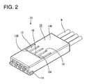
- a connector C1 of this embodiment particularly is a joint connector provided with a housing 10 internally formed with one or more cavities 11 capable of at least partly accommodating one or more terminals 20, one or more locking lances 12 for retaining the one or more respective terminals 20 by being engaged with the terminals 20 at least partly inserted into the cavities 11, and at least one busbar 30 for shorting the terminals 20 at least partly accommodated in the cavities 11.
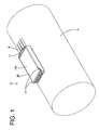
- This connector C1 preferably is used by being fixed to a main line A of a wiring harness by tape (not shown) as shown in FIG. 1 .
- a side to be connected with a mating connector is referred to as front or front side and left-lower, right-upper, upper and lower sides of FIG. 1 are referred to as front, rear, top and under sides in the respective constituent elements.
- the housing 10 is made e.g. of synthetic resin and has a (preferably substantially flat) box shape as a whole. At least one rib 13 is provided on a wall (top wall 10A) on the lateral or top side (particularly a side substantially opposite to a side in contact with the main line A of the wiring harness) out of outer walls of the housing 10.
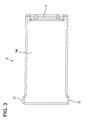
- the rib 13 projects outward or upward from the lateral or top wall 10A and extends substantially along the rear end of the housing 10 preferably substantially over the entire width of the housing 10 in a short side direction (see FIG. 3 ).
- One or more, preferably a pair of protrusions 14 projecting toward the (preferably substantially opposite) lateral side(s) are provided at or near the front end of the housing 10.
- the (preferably both) protrusions 14 are provided on the lateral or top side of the housing 10 and project along the lateral or top wall 10A.
- These rib(s) 13 and/or protrusion(s) 14 particularly prevent the tape fastening the connector C1 to the main line A of the wiring harness from being displaced forward or backward of the housing 10 to be loosened, whereby the connector C is firmly fixed to the main line A of the wiring harness.
- One or more (e.g. four) cavities 11 narrow and long in forward and backward directions are formed preferably substantially side by side in a width direction in the housing 10.
- the respective cavities 11 particularly have a substantially rectangular cross section one size larger than connecting portions 22 of the terminals 20 to be described later.
- the terminals 20 are to be at least partly inserted into the respective cavities 11 from an insertion side, preferably substantially from behind.
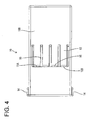
- An opening 15 for exposing the respective cavities 11 to the under side (outer side) of the housing 10 is formed in the lateral (under) wall 10B (outer wall) of the housing 10 (see FIG. 4 ).
- the opening 15 is formed in a middle or intermediate part of the housing 10 in forward and backward directions and/or has a substantially rectangular shape long in the width direction of the housing 10.
- the locking lances 12 are formed at the lateral (under) wall 10B of the housing 10.
- the locking lances 12 are substantially in the form of cantilevers extending substantially forward from (preferably the rear edge of) the opening 15 of the housing 10.
- One or more (e.g. four) locking lances 12 are provided and preferably all of them are of substantially the same shape and size.
- the four locking lances 12 particularly are arranged substantially side by side in the width direction substantially in conformity with the positions of the respective cavities 11 and the opening 15 is mostly covered by the locking lances 12.
- each locking lance 12 is so shaped that the front end (free end) thereof at least partly projects into the cavity 11, and this projecting part (called an engaging portion 12A) is to be engaged with an engageable portion 23 of the terminal 20 to prevent the terminal 20 from being withdrawn toward the insertion side e.g. backward.
- An inner part of a front end surface 12B of the locking lance 12 forms the front end surface of the engaging portion 12A.
- Each locking lance 12 is resiliently deformable substantially in a direction intersecting with an inserting direction of the terminal 20 or substantially in inward and outward directions of the housing 10.
- the engaging portion 12A moves onto the engageable portion 23 of the terminal 20 and the locking lance 12 substantially is resiliently deformed outwardly or toward the lateral or under side (outer side) to permit the insertion of the terminal 20.
- the position of the locking lance 12 at this time corresponds to a disengaging position.
- the terminal 20 is inserted to a substantially proper position (particularly a position where connection with the busbar 30 is secure)
- the locking lance 12 at least partly returns toward or to a natural state to be engaged with the terminal 20.
- the position of the locking lance 12 at this time corresponds to an engaging portion.
- the locking lance 12 at the engaging position preferably is so arranged as not to project outward from the housing 10 at all, and the outer or under surface of the locking lance 12 and that of the housing 10 (outer or under surface of the lateral or under wall 10B) form substantially flat surfaces (see FIG. 7 ).
- the locking lance 12 is resiliently deformed outward from the engaging position even to a small degree, a part (front end portion) thereof projects outward from the housing 10.
- the engaging portion 12A is left on the engageable portion 23 and the locking lance 12 projects from the lateral or under wall 10B of the housing 10 by that much.
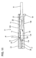
- a clearance between the front end surface 12B (corresponding to a preferred leading end surface of the locking lance) of the locking lance 12 and the opening 15 preferably serves as a jig hole 16, into which a disengaging jig J1 (corresponding to a preferred jig) is at least partly insertable (see FIG. 11 ).
- the leading end of the disengaging jig J1 at least partly inserted into the jig hole 16 is brought or bringable into engagement with the front end surface 12B of the locking lance 12 to resiliently deform the locking lance 12 towards or to the disengaging position.
- Each terminal 20 is made of an electrically conductive (preferably metal) plate material, and a wire connection portion (preferably comprising a barrel portion 21) to be connected (preferably crimped or bent or folded into connection) with an end portion of a wire W is provided at a rear side thereof.
- a connecting portion 22 substantially in the form of a (preferably substantially rectangular or polygonal) tube having open front and rear sides is provided at or near a front side of the terminal 20, and a terminal portion 31 of the busbar 30 mounted into the housing 10 is mounted to or at least partly inserted into the connecting portion 22 from a mounting side, preferably substantially from front. In this way, the busbar 30 and the terminal 20 are electrically connected.
- the connecting portion 22 of the terminal 20 includes the engageable portion 23 engageable with the engaging portion 12A of the locking lance 12.
- the engageable portion 23 is located at a position in the front half of the connecting portion 22 (preferably substantially close to the front end of the connecting portion 22) and/or projects outward from the connecting portion 22.
- the rear surface of the engageable portion 23 is a surface inclined to gradually project backward toward the projecting end thereof, and the front surface of the engaging portion 12A is engaged with this surface from the side of the insertion side, preferably substantially from behind.
- the busbar 30 is formed of an electrically conductive metal material to have a substantially flat shape, and includes a plurality of (e.g. four) tab-shaped terminal portions 31 (see FIG. 6 ).
- the four terminal portions 31 are connected by a connecting portion 32 and provided substantially parallel to each other at the substantially same intervals as the arrangement intervals of the cavities 11.
- the busbar 30 is mounted into the housing 10 by pressing the terminal portions 31 into the corresponding cavities 11 from the mounting side, preferably substantially from front.
- the respective terminal portions 31 at least partly project into the corresponding cavities 11 to be connected with the connecting portions 22 of the respective terminals 20 accommodated in the cavities 11.
- the front end surface 12B of the locking lance 12 preferably is inclined to gradually project forward toward an inner side of the housing 10. This inclination is substantially equal to that of the rear surface of the engageable portion 23 of the terminal 20.
- a facing surface 15A of the under wall 10B facing the front end surfaces 12B of the locking lances 12 (front part of the peripheral surface of the opening 15) preferably is inclined to gradually project backward (toward the locking lances 12) toward an outer side of the housing 10. This inclination preferably is substantially equal to that of the front end surfaces 12B of the locking lances 12, and/or the front end surfaces 12B of the locking lances 12 and the facing surface 15A of the housing 10 are substantially parallel when the locking lances 12 are at the engaging positions.
- the inclination of the front end surface 12B of each locking lance 12, that of the facing surface 15A of the housing 10 and/or the spacing between the front end surface 12B and the facing surface 15A is/are set such that the front end surface 12B and the facing surface 15A do not touch each other when the resilient deformation of the locking lance 12 are in a range up to the disengaging position while touching each other when the locking lance 12 is deformed outward beyond the disengaging position.
- the jig holes 16 obliquely extend since the front end surfaces 12B of the locking lances 12 and the facing surface 15A of the housing 10 are inclined.
- the jig holes 16 obliquely penetrate the under wall 10B of the housing 10 toward an upper rear side from the cavities 11.
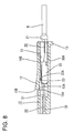
- the engaging portion 12A of the locking lance 12 moves onto the engageable portion 23 of the terminal 20 and the locking lance 12 is resiliently deformed outward as shown in FIG. 8 . Then, the locking lance 12 reaches the disengaging position and the terminal 20 moves forward in the cavity 11. At this time, the front end surface 12B of the locking lance 12 does not come into contact with the facing surface 15A of the housing 10, wherefore the terminal 20 can be smoothly inserted.
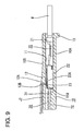
- a detecting jig J2 is or can be slid backward from the front side along the under wall 10B of the housing 10 (see FIG. 9 ).
- the detecting jig J2 comes into contact with the front end surface 12B of the locking lance 12 to have a sliding movement hindered since the front end portion of the locking lance 12 projects outward from the housing 10.
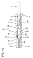
- the detecting jig J2 is or can be slid backward along the under surface of the housing 10 without touching any locking lance 12 since the locking lances 12 are at the engaging positions and do not project outward from the housing 10 as shown in FIG. 10 . Therefore, the insufficient insertion of the terminals 20 can be detected by sliding the detecting jig J2.
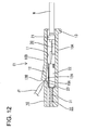
- the leading end of the disengaging jig J1 is at least partly inserted into the jig hole 16 to be engaged with the front end surface 12B of the locking lance 12 and lift the locking lance 12 outward as shown in FIGS. 11 and 12 .
- the end edge (innermost edge) of the front end surface 12B of the locking lance 12 preferably comes substantially into contact with (preferably a substantially central position of) the facing surface 15A of the housing 10 in inward and outward directions to prevent any further displacement of the locking lance 12. Accordingly, the locking lance 12 can be prevented from being resiliently deformed outward beyond the disengaging position, i.e. from being excessively deformed.
- the jig holes 16 of the housing 10 of this embodiment are formed by removing mold pieces (not shown) obliquely toward an upper rear side upon forming the housing 10.
- the jig holes 16 are, for example, formed in a direction substantially orthogonal to forward and backward directions of the housing 10 instead of being obliquely formed as in this embodiment, the spacing between the front end surfaces of the locking lances and the facing surface needs to be very narrow in order to realize the above setting (such setting that the front end surface of the locking lance comes into contact with the facing surface when the locking lance is resiliently deformed outward beyond the disengaging position).
- the front end surfaces 12B of the locking lances 12 preferably are inclined to gradually project forward toward the inner side of the housing 10, the facing surface 15A of the housing 10 is inclined to gradually project toward the locking lances 12 toward the outer side of the housing 10 and/or the front end surfaces 12B of the locking lances 12 come into contact with the facing surface 15A if the locking lances 12 are resiliently deformed outward beyond the disengaging positions.
- the outward resilient deformations of the locking lances 12 beyond the disengaging positions, i.e. prevent the excessive deformations of the locking lances 12.
- the connector C2 of this embodiment differs from the first embodiment in that one or more catching portions 50 engageable with the disengaging jig J1 are provided in or at or on the front end surfaces 12B of the locking lances 12. Constructions similar to the first embodiment are identified by the same reference numerals and not repeatedly described.
- the connector C2 is provided with a housing 10 internally formed with one or more cavities 11 capable of at least partly accommodating one or more terminals 20 and one or more locking lances 12 for retaining the respective terminals 20 by being engaged with the terminals 20 at least partly inserted into the cavities 11 similar to the first embodiment.
- the locking lances 12 are formed at an under or lateral wall 10B of the housing 10 and resiliently deformable in inward and outward directions between engaging positions to be engaged with the terminals 20 and disengaging positions to permit the insertion and withdrawal of the terminals 20. Further, similar to the first embodiment, the leading end of the disengaging jig J1 is brought or bringable into engagement with a front end surface 12B of the locking lance 12 to resiliently deform the locking lance 12 to the disengaging position upon withdrawing the terminal 20 from the cavity 11.
- the at least one catching portion 50 is provided in or at or on the front end surface 12B of each locking lance 12.
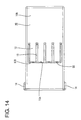
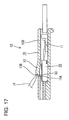
- the catching portion 50 preferably is a recess formed in the front end surface 12B of the locking lance 12, and a recessing direction thereof preferably is substantially parallel to the under wall 10B of the housing 10 when the locking lance 12 is at the engaging position (see FIG. 16 ).
- the catching portion 50 is formed at a widthwise intermediate position (preferably a substantially widthwise central position) of the locking lance 12 and/or has a substantially arcuate shape as shown in FIG. 15 when viewed from front, and a tip thereof at the outermost or undermost side is located substantially in the center of the locking lance 12 in inward and outward directions, i.e. located above a part of the front end surface 12B of the locking lance 12 to be engaged with a rear surface 23A of an engageable portion 23 of the terminal 20.
- the front end surfaces 12B of the locking lances 12 preferably are inclined to gradually project forward toward an inner side of the housing 10
- a facing surface 15A of the housing 10 preferably is inclined to gradually project toward the locking lances 12 toward an outer side of the housing 10 and the front end surfaces 12B of the locking lances 12 come into contact with the facing surface 15A if the locking lances 12 are resiliently deformed outward beyond the disengaging positions.
- excessive deformations of the locking lances 12 can be prevented.
- the locking lances 12 can be resiliently deformed by engaging the disengaging jig J1 with the catching portions 50.
- the disengaging jig J1 can be prevented from sliding on the front end surfaces 12B of the locking lances 12 and the locking lances 12 can be easily disengaged.
- the catching portion 50 preferably is formed in the widthwise center of the locking lance 12, force of the disengaging jig J1 for resiliently deforming the locking lance 12 acts on the locking lance 12 in a well-balanced manner and the locking lance 12 can be more easily disengaged.
- one or more locking lances 12 are formed at an outer wall 10B of a housing 10 and resiliently deformable between engaging positions to be engaged with one or more respective terminals 20 and disengaging positions reached by outward resiliently deformations from the engaging positions to permit the insertion and withdrawal of the one or more respective terminals 20.
- At least part of the leading end surfaces 12B of the locking lances 12 are inclined to gradually project forward toward an inner side of the housing 10, a facing surface 15A of the outer wall 10B of the housing 10 facing the leading end surfaces 12B of the locking lances 12 is inclined to gradually project toward the locking lances 12 toward an outer side of the housing 10, and the leading end surfaces 12B of the locking lances 12 can come into contact with the facing surface 15A when the locking lances 12 are resiliently deformed outward beyond the disengaging positions.
- one or more branch lines B such as signal wires from a main line A1 formed by bundling one or more power wires and/or one or more signal wires are branch-connected with a device (not shown).
- a construction common (i.e. similar or substantially same) to the first embodiment is identified by the same reference numerals.
- a wiring harness WH of this embodiment uses the main line A1 preferably made up of aluminum wires, in each of which a core preferably is formed by twisting a plurality of strands made of aluminum or aluminum alloy and covered by an insulation coating made e.g. of synthetic resin.
- a nonconductive film such as an oxide film is likely to be formed on the outer surface of the (preferably aluminum) wire and, in the case of branch connection with a device-side wire W1 which is to be electrically connected with an external electric or electronic device (such as a junction box, a load, a sensor or the like), the film on the outer surface typically cannot be sufficiently scraped off only by pressing the (aluminum) wire into between contact blades and problems such as a connection error and an increase of contact resistance are likely to occur if an insulation displacement terminal provided with a pair of contact blades facing each other is used (see, for example, Japanese Unexamined Patent Publication No. 2007-87861 ).
- the terminal 20 preferably is crimped or bent or folded into connection with an end portion of the branch line B made of the (preferably aluminum) wire and at least partly inserted into a respective cavity 11 of a connector C1.
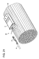
- the wiring harness WH includes the main line A1 and the connector C1 mounted or placed on or to the outer circumferential surface of this main line A1.
- the connector C1 is fixed to the main line A1 by winding a fixing member 60 such as a tape, clip, cable tie, strap band or the like.
- the branch lines B are drawn out from the main line A1 and cut, and one or more terminals 20 are electrically connected with end portions of the (preferably both) branch line(s) B. These terminals 20 are at least partly inserted into the one or more respective cavities 11.
- the both terminals 20 preferably are connected while being shorted by a busbar 30. Therefore, the branch lines B are electrically connected via the busbar 30.
- the device includes the device-side wire W1.
- the terminal 20 is to be electrically connected with an end portion of the device-side wire W1.
- the connector C1 is formed with one or more (e.g. four) cavities 11, part of (e.g. two) cavities 11 are or may be empty with the both terminals 20 of the branch lines B connected with the connector C1.
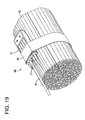
- the terminal 20 of the device-side wire W1 is at least partly inserted into either one of the two empty cavities 11 as shown in FIG. 19 , it is electrically connected with the terminals 20 of the branch lines B via the busbar 30.
- the branch lines B are or may be electrically connected with the device-side wire W1 via the busbar 30 and the terminals 20.
- the branch lines B are branch-connected with the device-side wire W1.
- the terminal 20 of the device-side wire W1 into the cavity 11 of the connector C1 in the case of branch connection of the branch lines B with the device-side wire W1, whereby the branch lines B are branch-connected with the device-side wire W1 via the busbar 30.
- connection reliability can be improved as compared with branch connection of the branch lines B with the device-side wire W1 using insulation displacement terminals. Therefore, the device can be attached later if necessary.
- a connector C1 is not mounted on a main line A1 beforehand and a branch line B from the main line A1 is branch-connected using the connector C1 when it is necessary to attach a device later.
- a construction common (i.e. similar or substantially same) to the first embodiment is identified by the same reference numerals.
- a wiring harness WH of this embodiment uses the main line A1 preferably made up of aluminum wires and is similar to the third embodiment in this point.
- the necessary branch line B is drawn out from the main line A1 and cut and terminals 20 are electrically connected with both end portions of the cut branch line B.
- the connector C1 is brought and the terminals 20 are respectively at least partly inserted into cavities 11 of the connector C1.
- both terminals 20 are or may be connected while being shorted via a busbar 30 and the branch line B is electrically connected via the busbar 30.
- the wiring harness WH is completed.
- a terminal 20 is electrically connected with an end portion of a device-side wire W1 and at least partly inserted into a cavity 11 of the connector C1. Then, the terminal 20 of the device-side wire W1 is or may be electrically connected with the terminals 20 of the branch line B via the busbar 30. In this way, the branch line B is electrically connected with the device-side wire W1 via the terminals 20 and the busbar 30, thereby being branch-connected with the device-side wire W1.
- connection reliability can be improved as compared with branch connection of the branch line B with the device-side wire W1 using insulation displacement terminals. Further, the device can be attached later if necessary even when the connector C1 is not mounted on the main line A1 beforehand.
Landscapes
- Connector Housings Or Holding Contact Members (AREA)
Applications Claiming Priority (2)
| Application Number | Priority Date | Filing Date | Title |
|---|---|---|---|
| JP2008178372 | 2008-07-08 | ||
| JP2009119248A JP2010040508A (ja) | 2008-07-08 | 2009-05-15 | コネクタおよびワイヤハーネス |
Publications (1)
| Publication Number | Publication Date |
|---|---|
| EP2144335A1 true EP2144335A1 (de) | 2010-01-13 |
Family
ID=41078236
Family Applications (1)
| Application Number | Title | Priority Date | Filing Date |
|---|---|---|---|
| EP09007948A Withdrawn EP2144335A1 (de) | 2008-07-08 | 2009-06-17 | Steckverbinder, Kabelbaum mit diesem Steckverbinder und Verbindungsverfahren |
Country Status (3)
| Country | Link |
|---|---|
| US (1) | US7862374B2 (de) |
| EP (1) | EP2144335A1 (de) |
| JP (1) | JP2010040508A (de) |
Cited By (2)
| Publication number | Priority date | Publication date | Assignee | Title |
|---|---|---|---|---|
| EP2437357A1 (de) * | 2010-10-01 | 2012-04-04 | Sumitomo Wiring Systems, Ltd. | Steckverbinder |
| WO2012111859A1 (en) * | 2011-02-18 | 2012-08-23 | Yazaki Corporation | Joint connector |
Families Citing this family (14)
| Publication number | Priority date | Publication date | Assignee | Title |
|---|---|---|---|---|
| JP5642504B2 (ja) * | 2010-10-29 | 2014-12-17 | 矢崎総業株式会社 | ジョイントコネクタ |
| JP2012169185A (ja) * | 2011-02-15 | 2012-09-06 | Yazaki Corp | ジョイントコネクタ装置 |
| JP2012169184A (ja) * | 2011-02-15 | 2012-09-06 | Yazaki Corp | ジョイントコネクタ、及びコネクタ組み立て装置 |
| JP2014011148A (ja) * | 2012-07-03 | 2014-01-20 | Yazaki Corp | コネクタ |
| JP2014013682A (ja) * | 2012-07-04 | 2014-01-23 | Yazaki Corp | コネクタ用ハウジング |
| JP6141612B2 (ja) * | 2012-09-21 | 2017-06-07 | 矢崎総業株式会社 | コネクタ |
| JP2015069748A (ja) * | 2013-09-27 | 2015-04-13 | 住友電装株式会社 | コネクタ付ワイヤハーネスの防水構造 |
| JP2016031801A (ja) * | 2014-07-28 | 2016-03-07 | 矢崎総業株式会社 | コネクタ |
| US9608355B2 (en) * | 2015-05-28 | 2017-03-28 | Yazaki Corporation | Connector having a retainer with outer surface flush with outer surface of the connector housing |
| JP6539634B2 (ja) * | 2016-10-17 | 2019-07-03 | 矢崎総業株式会社 | コネクタ |
| JP6819510B2 (ja) | 2017-08-16 | 2021-01-27 | 株式会社オートネットワーク技術研究所 | コネクタ |
| US10697637B2 (en) * | 2017-11-22 | 2020-06-30 | General Electric Company | System for oxidant intake |
| JP7123858B2 (ja) * | 2019-05-24 | 2022-08-23 | 矢崎総業株式会社 | コネクタ及びワイヤーハーネス |
| JP7734963B2 (ja) * | 2021-12-03 | 2025-09-08 | 日本圧着端子製造株式会社 | コネクタ |
Citations (7)
| Publication number | Priority date | Publication date | Assignee | Title |
|---|---|---|---|---|
| US3917371A (en) * | 1972-04-06 | 1975-11-04 | Shinagawa Automotive Electric | Electrical connecting apparatus |
| US5456617A (en) * | 1993-03-03 | 1995-10-10 | Sumitomo Wiring Systems, Ltd. | Joint connector |
| US5769663A (en) * | 1994-12-09 | 1998-06-23 | Yazaki Corporation | Connector housing |
| EP1045482A2 (de) * | 1999-04-13 | 2000-10-18 | Sumitomo Wiring Systems, Ltd. | Verbinder |
| US20010006861A1 (en) * | 1999-12-27 | 2001-07-05 | Yazaki Corporation | Double locked terminal connector |
| JP2004014220A (ja) | 2002-06-05 | 2004-01-15 | Sumitomo Wiring Syst Ltd | ジョイントコネクタ |
| JP2007087861A (ja) | 2005-09-26 | 2007-04-05 | Yazaki Corp | 圧接端子 |
Family Cites Families (8)
| Publication number | Priority date | Publication date | Assignee | Title |
|---|---|---|---|---|
| JPS59117073U (ja) * | 1983-01-27 | 1984-08-07 | 東洋ハ−ネス株式会社 | コネクタハウジング用端子 |
| US4690477A (en) * | 1985-04-30 | 1987-09-01 | E. I. Du Pont De Nemours And Company | Electrical connector apparatus |
| JP2910623B2 (ja) * | 1995-06-06 | 1999-06-23 | 住友電装株式会社 | ジョイントコネクタ、端子金具及びコネクタハウジング |
| JPH11167947A (ja) * | 1997-12-05 | 1999-06-22 | Yazaki Corp | コネクタ |
| JPH11238542A (ja) * | 1998-02-20 | 1999-08-31 | Yazaki Corp | コネクタ |
| US6146200A (en) * | 1998-06-04 | 2000-11-14 | Sumitomo Wiring Systems, Ltd. | Connector and a cap therefor |
| JP4013412B2 (ja) * | 1999-07-28 | 2007-11-28 | 住友電装株式会社 | コネクタ |
| DE102004034396B4 (de) * | 2003-07-17 | 2011-12-22 | Autonetworks Technologies, Ltd. | Verbindungsteil und Verbindungsstecker für einen Kabelbaum |
-
2009
- 2009-05-15 JP JP2009119248A patent/JP2010040508A/ja active Pending
- 2009-06-17 EP EP09007948A patent/EP2144335A1/de not_active Withdrawn
- 2009-06-19 US US12/487,867 patent/US7862374B2/en not_active Expired - Fee Related
Patent Citations (7)
| Publication number | Priority date | Publication date | Assignee | Title |
|---|---|---|---|---|
| US3917371A (en) * | 1972-04-06 | 1975-11-04 | Shinagawa Automotive Electric | Electrical connecting apparatus |
| US5456617A (en) * | 1993-03-03 | 1995-10-10 | Sumitomo Wiring Systems, Ltd. | Joint connector |
| US5769663A (en) * | 1994-12-09 | 1998-06-23 | Yazaki Corporation | Connector housing |
| EP1045482A2 (de) * | 1999-04-13 | 2000-10-18 | Sumitomo Wiring Systems, Ltd. | Verbinder |
| US20010006861A1 (en) * | 1999-12-27 | 2001-07-05 | Yazaki Corporation | Double locked terminal connector |
| JP2004014220A (ja) | 2002-06-05 | 2004-01-15 | Sumitomo Wiring Syst Ltd | ジョイントコネクタ |
| JP2007087861A (ja) | 2005-09-26 | 2007-04-05 | Yazaki Corp | 圧接端子 |
Cited By (2)
| Publication number | Priority date | Publication date | Assignee | Title |
|---|---|---|---|---|
| EP2437357A1 (de) * | 2010-10-01 | 2012-04-04 | Sumitomo Wiring Systems, Ltd. | Steckverbinder |
| WO2012111859A1 (en) * | 2011-02-18 | 2012-08-23 | Yazaki Corporation | Joint connector |
Also Published As
| Publication number | Publication date |
|---|---|
| US7862374B2 (en) | 2011-01-04 |
| US20100009568A1 (en) | 2010-01-14 |
| JP2010040508A (ja) | 2010-02-18 |
Similar Documents
| Publication | Publication Date | Title |
|---|---|---|
| US7862374B2 (en) | Connector having a locking lance | |
| EP1005106B1 (de) | Anschluss und Anpressverfahren | |
| JP6592127B2 (ja) | 端子金具 | |
| EP2164137B1 (de) | Steckverbinder, Anschlussklemme, Kabelbaum mit einem Steckverbinder und Verfahren zu seinem Zusammenbau | |
| US7114988B2 (en) | Connector for connecting a flat cable and for securely retaining the same | |
| EP2081259B1 (de) | Steckverbinder | |
| US7985106B2 (en) | Female type terminal pin | |
| US7938694B2 (en) | Connector terminal and connector with the connector terminal | |
| EP2239814A1 (de) | Anschlusskontakt, Stecker und Montageverfahren | |
| EP2081260A1 (de) | Steckverbinder | |
| EP2947720A1 (de) | Steckverbinder | |
| EP2852004B1 (de) | Anschlussstück | |
| EP2375506A1 (de) | Verbindungsstruktur für Anschlussstück | |
| EP2244334A1 (de) | Anschlussstück und Verfahren zu dessen Herstellung | |
| JP4555223B2 (ja) | 接続端子 | |
| JP2018524785A (ja) | 端子金具 | |
| KR100702399B1 (ko) | 플랙시블 프린트배선판 압착단자 및 이것을 이용한 코어의압착구조 | |
| CN101904058A (zh) | 连接器及使用该连接器的电线短路方法 | |
| EP1986283A1 (de) | Steckverbinder und Montageverfahren dafür | |
| US7226320B2 (en) | Connector having an improved locking structure | |
| CN114122773A (zh) | 用于功率连接器组件的插入式线连接器 | |
| EP1548894B1 (de) | Verbinder | |
| US7044786B2 (en) | Connector and method of assembling a connector | |
| EP1821375A2 (de) | Ein Anschlussstück, eine Methode zum Crimpen dieses Anschlussstücks und ein Positioniergestell | |
| EP1693927A1 (de) | Anschlusselement , dazugehöriger Verbinder und Verfahren zur Herstellung |
Legal Events
| Date | Code | Title | Description |
|---|---|---|---|
| PUAI | Public reference made under article 153(3) epc to a published international application that has entered the european phase |
Free format text: ORIGINAL CODE: 0009012 |
|
| 17P | Request for examination filed |
Effective date: 20090625 |
|
| AK | Designated contracting states |
Kind code of ref document: A1 Designated state(s): AT BE BG CH CY CZ DE DK EE ES FI FR GB GR HR HU IE IS IT LI LT LU LV MC MK MT NL NO PL PT RO SE SI SK TR |
|
| 17Q | First examination report despatched |
Effective date: 20100310 |
|
| STAA | Information on the status of an ep patent application or granted ep patent |
Free format text: STATUS: THE APPLICATION IS DEEMED TO BE WITHDRAWN |
|
| 18D | Application deemed to be withdrawn |
Effective date: 20130103 |