EP2144748B1 - Reifenkarkassenformverfahren und -trommel - Google Patents
Reifenkarkassenformverfahren und -trommel Download PDFInfo
- Publication number
- EP2144748B1 EP2144748B1 EP08719381A EP08719381A EP2144748B1 EP 2144748 B1 EP2144748 B1 EP 2144748B1 EP 08719381 A EP08719381 A EP 08719381A EP 08719381 A EP08719381 A EP 08719381A EP 2144748 B1 EP2144748 B1 EP 2144748B1
- Authority
- EP
- European Patent Office
- Prior art keywords
- drum
- annular
- bladder
- relative
- turn
- Prior art date
- Legal status (The legal status is an assumption and is not a legal conclusion. Google has not performed a legal analysis and makes no representation as to the accuracy of the status listed.)
- Not-in-force
Links
Images


Classifications
-
- B—PERFORMING OPERATIONS; TRANSPORTING
- B29—WORKING OF PLASTICS; WORKING OF SUBSTANCES IN A PLASTIC STATE IN GENERAL
- B29D—PRODUCING PARTICULAR ARTICLES FROM PLASTICS OR FROM SUBSTANCES IN A PLASTIC STATE
- B29D30/00—Producing pneumatic or solid tyres or parts thereof
- B29D30/06—Pneumatic tyres or parts thereof (e.g. produced by casting, moulding, compression moulding, injection moulding, centrifugal casting)
- B29D30/08—Building tyres
- B29D30/20—Building tyres by the flat-tyre method, i.e. building on cylindrical drums
- B29D30/24—Drums
-
- B—PERFORMING OPERATIONS; TRANSPORTING
- B29—WORKING OF PLASTICS; WORKING OF SUBSTANCES IN A PLASTIC STATE IN GENERAL
- B29D—PRODUCING PARTICULAR ARTICLES FROM PLASTICS OR FROM SUBSTANCES IN A PLASTIC STATE
- B29D30/00—Producing pneumatic or solid tyres or parts thereof
- B29D30/06—Pneumatic tyres or parts thereof (e.g. produced by casting, moulding, compression moulding, injection moulding, centrifugal casting)
- B29D30/08—Building tyres
- B29D30/20—Building tyres by the flat-tyre method, i.e. building on cylindrical drums
- B29D30/32—Fitting the bead-rings or bead-cores; Folding the textile layers around the rings or cores
-
- B—PERFORMING OPERATIONS; TRANSPORTING
- B29—WORKING OF PLASTICS; WORKING OF SUBSTANCES IN A PLASTIC STATE IN GENERAL
- B29D—PRODUCING PARTICULAR ARTICLES FROM PLASTICS OR FROM SUBSTANCES IN A PLASTIC STATE
- B29D30/00—Producing pneumatic or solid tyres or parts thereof
- B29D30/06—Pneumatic tyres or parts thereof (e.g. produced by casting, moulding, compression moulding, injection moulding, centrifugal casting)
- B29D30/08—Building tyres
- B29D30/20—Building tyres by the flat-tyre method, i.e. building on cylindrical drums
- B29D30/24—Drums
- B29D30/244—Drums for manufacturing substantially cylindrical tyre components with cores or beads, e.g. carcasses
- B29D30/245—Drums for the single stage building process, i.e. the building-up of the cylindrical carcass and the toroidal expansion of it are realised on the same drum
-
- B—PERFORMING OPERATIONS; TRANSPORTING
- B29—WORKING OF PLASTICS; WORKING OF SUBSTANCES IN A PLASTIC STATE IN GENERAL
- B29D—PRODUCING PARTICULAR ARTICLES FROM PLASTICS OR FROM SUBSTANCES IN A PLASTIC STATE
- B29D30/00—Producing pneumatic or solid tyres or parts thereof
- B29D30/06—Pneumatic tyres or parts thereof (e.g. produced by casting, moulding, compression moulding, injection moulding, centrifugal casting)
- B29D30/08—Building tyres
- B29D30/20—Building tyres by the flat-tyre method, i.e. building on cylindrical drums
- B29D30/24—Drums
- B29D30/26—Accessories or details, e.g. membranes, transfer rings
-
- B—PERFORMING OPERATIONS; TRANSPORTING
- B29—WORKING OF PLASTICS; WORKING OF SUBSTANCES IN A PLASTIC STATE IN GENERAL
- B29D—PRODUCING PARTICULAR ARTICLES FROM PLASTICS OR FROM SUBSTANCES IN A PLASTIC STATE
- B29D30/00—Producing pneumatic or solid tyres or parts thereof
- B29D30/06—Pneumatic tyres or parts thereof (e.g. produced by casting, moulding, compression moulding, injection moulding, centrifugal casting)
- B29D30/08—Building tyres
- B29D30/20—Building tyres by the flat-tyre method, i.e. building on cylindrical drums
- B29D30/24—Drums
- B29D30/26—Accessories or details, e.g. membranes, transfer rings
- B29D2030/2614—Bladders associated with the building drum, e.g. bladders used for the toroidal expansion, bladders for turning-up the plies
-
- B—PERFORMING OPERATIONS; TRANSPORTING
- B29—WORKING OF PLASTICS; WORKING OF SUBSTANCES IN A PLASTIC STATE IN GENERAL
- B29D—PRODUCING PARTICULAR ARTICLES FROM PLASTICS OR FROM SUBSTANCES IN A PLASTIC STATE
- B29D30/00—Producing pneumatic or solid tyres or parts thereof
- B29D30/06—Pneumatic tyres or parts thereof (e.g. produced by casting, moulding, compression moulding, injection moulding, centrifugal casting)
- B29D30/08—Building tyres
- B29D30/20—Building tyres by the flat-tyre method, i.e. building on cylindrical drums
- B29D30/32—Fitting the bead-rings or bead-cores; Folding the textile layers around the rings or cores
- B29D2030/3221—Folding over means, e.g. bladders or rigid arms
- B29D2030/3228—Folding over means, e.g. bladders or rigid arms using one bladder acting on each side of the drum
-
- B—PERFORMING OPERATIONS; TRANSPORTING
- B29—WORKING OF PLASTICS; WORKING OF SUBSTANCES IN A PLASTIC STATE IN GENERAL
- B29D—PRODUCING PARTICULAR ARTICLES FROM PLASTICS OR FROM SUBSTANCES IN A PLASTIC STATE
- B29D30/00—Producing pneumatic or solid tyres or parts thereof
- B29D30/06—Pneumatic tyres or parts thereof (e.g. produced by casting, moulding, compression moulding, injection moulding, centrifugal casting)
- B29D30/08—Building tyres
- B29D30/20—Building tyres by the flat-tyre method, i.e. building on cylindrical drums
- B29D30/32—Fitting the bead-rings or bead-cores; Folding the textile layers around the rings or cores
- B29D2030/3221—Folding over means, e.g. bladders or rigid arms
- B29D2030/3235—Folding over means, e.g. bladders or rigid arms using two or more bladders acting on each side of the drum
-
- B—PERFORMING OPERATIONS; TRANSPORTING
- B29—WORKING OF PLASTICS; WORKING OF SUBSTANCES IN A PLASTIC STATE IN GENERAL
- B29D—PRODUCING PARTICULAR ARTICLES FROM PLASTICS OR FROM SUBSTANCES IN A PLASTIC STATE
- B29D30/00—Producing pneumatic or solid tyres or parts thereof
- B29D30/06—Pneumatic tyres or parts thereof (e.g. produced by casting, moulding, compression moulding, injection moulding, centrifugal casting)
- B29D30/08—Building tyres
- B29D30/20—Building tyres by the flat-tyre method, i.e. building on cylindrical drums
- B29D30/32—Fitting the bead-rings or bead-cores; Folding the textile layers around the rings or cores
- B29D2030/3221—Folding over means, e.g. bladders or rigid arms
- B29D2030/3242—Folding over means, e.g. bladders or rigid arms and with means for pressing the bladder against the ply material, e.g. bladder guide shoes, cages, arms
-
- B—PERFORMING OPERATIONS; TRANSPORTING
- B29—WORKING OF PLASTICS; WORKING OF SUBSTANCES IN A PLASTIC STATE IN GENERAL
- B29D—PRODUCING PARTICULAR ARTICLES FROM PLASTICS OR FROM SUBSTANCES IN A PLASTIC STATE
- B29D30/00—Producing pneumatic or solid tyres or parts thereof
- B29D30/06—Pneumatic tyres or parts thereof (e.g. produced by casting, moulding, compression moulding, injection moulding, centrifugal casting)
- B29D30/08—Building tyres
- B29D30/20—Building tyres by the flat-tyre method, i.e. building on cylindrical drums
- B29D30/32—Fitting the bead-rings or bead-cores; Folding the textile layers around the rings or cores
- B29D2030/3221—Folding over means, e.g. bladders or rigid arms
- B29D2030/3242—Folding over means, e.g. bladders or rigid arms and with means for pressing the bladder against the ply material, e.g. bladder guide shoes, cages, arms
- B29D2030/325—Folding over means, e.g. bladders or rigid arms and with means for pressing the bladder against the ply material, e.g. bladder guide shoes, cages, arms the means being radially expandable and contractible
Definitions
- the present invention relates to a tyre carcass forming method and drum.
- the present invention relates to an improvement to a known forming method, which employs a drum comprising two half-drums movable axially in opposite directions to and from a central plane of the drum, and comprising respective turn-up bladders.
- a tyre carcass is formed by:
- each turn-up bladder is known to be associated with at least one respective push bladder located axially outwards of the relative turn-up bladder, and which, when inflated, presses the relative turn-up bladder against the relative sidewall of the central portion of the body ply. When so pressed, the turn-up bladder expands radially outwards to increase the portion of its outer surface adhering to the relative sidewall of the central portion, and so complete turn-up of the relative annular lateral portion of the body ply.
- push bladders also pose size problems, by being located at least partly outwards of the relative turn-up bladders on the half-drums.
- the half-drums must be built long enough to support the relative push bladders, which means an increase in size, stronger drum supporting structures as a whole, and considerable added cost.
- the present invention also relates to a tyre carcass forming drum.
- a tyre carcass forming drum as claimed in Claim 22 and preferably in any one of the following Claims depending directly or indirectly on Claim 22.
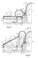
- Number 1 in Figures 1 to 4 indicates as a whole a drum for forming a vehicle tyre carcass 2 ( Figure 4 ).
- Drum 1 has a longitudinal axis 3 and a centre plane 4 perpendicular to longitudinal axis 3, and comprises two rigid half-drums 5 (only one shown) of fixed axial length, which are positioned specularly with respect to centre plane 4, are coaxial with longitudinal axis 3, and are movable axially in opposite directions to and from centre plane 4 by a known powered screw-nut screw transmission not shown.
- Each half-drum 5 is fitted, at the end facing centre plane 4, with a respective known clamping device 6 for clamping a respective bead bundle 7, and supports a respective annular turn-up bladder 8, which lies, at rest, along half-drum 5, and has an inner annular fastening shoe 9 housed inside a respective annular groove 10 formed in a cylindrical outer surface 11 of half-drum 5, adjacent to clamping device 6.
- turn-up bladder 8 has an annular portion defining an outer annular fastening shoe 12, which, at rest, rests on outer surface 11.
- Each half-drum 5 comprises an elastic tubular membrane 13, which, at rest ( Figure 1 ), rests on outer surface 11 of half-drum 5 and beneath turn-up bladder 8, has an annular fastening shoe 14 housed inside an annular groove 15 formed in cylindrical outer surface 11 of half-drum 5, adjacent to the free end of half-drum 5, and terminates, at the opposite end to fastening shoe 14, with an end portion 16 located close to annular groove 10 and connected integrally to outer fastening shoe 12 of turn-up bladder 8.
- tubular membrane 13 decreases in thickness from fastening shoe 14, and is fitted inside with axial stiffeners 17 preferably defined by metal wires.
- each turn-up bladder 8 and relative tubular membrane 13 define, about outer surface 11 of relative half-drum 5, a single annular chamber 18, to which air inflation pressure can be applied by inflating it with compressed air by means of a known pneumatic circuit (not shown) communicating with annular chamber 18 via a conduit 19 extending through relative half-drum 5.
- a body ply 20 is wound about drum 1 in the rest position shown in Figure 1 , in which the two half-drums 5 are a maximum distance apart, and turn-up bladders 8 are fully deflated and rest on the outer surface of respective tubular membranes 13, which rest on outer surface 11 of relative half-drums 5.
- body ply 20 rests on each clamping device 6 with the interposition of a respective annular strip 21 defined by a lateral annular appendix of relative turn-up bladder 8, for the purpose explained below.
- clamping devices 6 define, on body ply 20, an annular central portion 22 between the two clamping devices 6; and two annular lateral portions 23, each extending outwards of relative clamping device 6 and surrounding relative turn-up bladder 8.
- body ply 20 is not applied directly contacting drum 1, which is fitted first with other component parts not shown for the sake of simplicity, and which normally comprise a composite layer defined by a central innerliner, two lateral abrasion strips, and two outer sidewall strips.
- a respective bead bundle 7 is then fitted to annular lateral portion 23 on each half-drum 5, and is clamped in position by expanding relative clamping device 6 in known manner ( Figure 2 ).
- compressed air is fed in known manner underneath annular central portion 22, and, at the same time, the two half-drums are moved towards each other and central plane 4 ( Figure 2 ) to form annular central portion 22 into a toroidal shape with two annular sidewalls 24 substantially perpendicular to longitudinal axis 3.
- the relative tubular membrane 13 being axially rigid, acts as a conical brace to prevent substantially axial movement, and only permit substantially radial movement, of any point P along relative outer fastening shoe 12. More specifically, as turn-up bladder 8 is distended, the conical brace defined by relative tubular membrane 13 guides each point P along a substantially circular trajectory T, which is perpendicular to outer surface 11 of half-drum 5 at the point of intersection with outer surface 11, and extends in a radial plane through longitudinal axis 3 and point P, and about a respective centre C located at relative fastening shoe 14.
- tubular membrane 13 decreases in thickness towards the centre plane, so that it flexes in much the same way as a leaf spring.
- a tubular membrane 13 of constant thickness (not shown), reinforced axially to brace and guide outer fastening shoe 12, is obviously also perfectly acceptable.
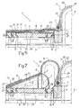
- each annular chamber 18 is divided into two annular chambers 25 and 26, communicating with respective feed conduits 27 and 28, by a respective radial push bladder 29, which, when expanded ( Figure 7 ), has a section substantially in the form of an isosceles triangle with its apex facing the free end of half-drum 5, a radially inner side 30 contacting outer surface 11 of half-drum 5, and a radially outer side 31 covered with tubular membrane 13 and supporting outer fastening shoe 12 of turn-up bladder 8 at the end facing centre plane 4.
- Radial push bladder 29 is connected to half-drum 5 by two fastening shoes 32 and 33 connected to the outer ends of respective sides 30, 31, and housed in respective annular grooves formed in half-drum 5, on opposite sides of conduit 27.
- each half-drum 5 only supports a turn-up bladder 34 comprising a portion 35 corresponding in shape and size to a turn-up bladder 8, and secured to half-drum 5 by an inner fastening shoe 36 corresponding to an inner fastening shoe 9; and a further portion 37, which, at one end, has an inner annular end portion 38 integral with an outer end portion of portion 35, and is secured to half-drum 5, at the other end, by an outer fastening shoe 39 corresponding to a fastening shoe 14.
- Portion 37 is reinforced with longitudinal ribs 40, which are fitted integrally to the outer surface of portion 37, extend the whole length of portion 37, and provide for bracing and guiding each point P of inner annular end portion 38 along trajectory T and about centre C as described with reference to the Figure 1-5 embodiment.
Landscapes
- Engineering & Computer Science (AREA)
- Mechanical Engineering (AREA)
- Manufacturing & Machinery (AREA)
- Tyre Moulding (AREA)
Claims (34)
- Verfahren zum Bilden einer Reifenkarkasse (2), wobei das Verfahren die nachfolgenden Schritte umfasst:Vorbereiten einer Trommel (1), die eine Längsachse (3) aufweist und zwei von fester axialer Länge seiende Halbtrommeln (5) umfasst, die in entgegengesetzten Richtungen entlang der Längsachse (3) zu einer Mittelebene (4) der Trommel (1) hin und von dieser weg bewegbar und außen mit jeweiligen Aufdrehbalgen (8; 34) bedeckt sind;Wickeln einer Körperlage (20) um die Trommel (1) derart, dass zwei ringförmige seitliche Abschnitte (23) der Körperlage (20) an wenigstens einem Teil der jeweiligen Aufdrehbalge (8; 34) liegen;Passen eines jeweiligen Wulstbündels (7) an jede Halbtrommel (5) und jeden jeweiligen ringförmigen seitlichen Abschnitt (23); wobei sich jeder ringförmige seitliche Abschnitt (23) auswärts von dem jeweiligen Wulstbündel (7) erstreckt;Klemmen jedes Wulstbündels (7) in einer Position an der jeweiligen Halbtrommel (5);sobald der ringförmige mittlere Abschnitt (22) geformt ist, erfolgendes Bilden eines ringförmigen mittleren Abschnittes (22), der sich zwischen den beiden Wulstbündeln (7) erstreckt, der Körperlage (22) zu einer toroidalen Form durch aufeinander zu erfolgendes Bewegen der beiden Halbtrommeln (5); undAusüben eines Luftaufblasdruckes zum nach außen erfolgenden Erweitern der ringförmigen seitlichen Abschnitte (23) etwa bis zu den jeweiligen Wulstbündeln (7);wobei das Verfahren des Weiteren die nachfolgenden Schritte umfasst:an jeder Halbtrommel (5) durch Ausüben des Luftaufblasdruckes erfolgendes Dehnen eines gegebenen ringförmigen Abschnittes (12; 38) des jeweiligen Aufdrehbalges (8; 34); undSteuern bzw. Regeln des Dehnens des ringförmigen Abschnittes (12; 38) unter Verwendung von Führungsmitteln (13; 40), die axial in Bezug auf die Halbtrommel (5) fest sind, mit dem ringförmigen Abschnitt (12; 38) starr sind und lediglich auf Ausübung des Luftaufblasdruckes reagieren; und zwar derart, dass der ringförmige Abschnitt (12; 38) in eine endgültige Position bewegt und bewirkt wird, dass ein Zwischenabschnitt, der sich zwischen dem ringförmigen Abschnitt (12; 38) und dem toroidalen ringförmigen mittleren Abschnitt (22) des Aufdrehbalges (8; 34) erstreckt, entlang einer jeweiligen Seitenwand (24) des toroidalen ringförmigen mittleren Abschnittes (22) nach außen rollt.
- Verfahren nach Anspruch 1, wobei die endgültige Position des ringförmigen Abschnittes (12; 38) eine mit der Längsachse (3) koaxiale Position ist; und die Führungsmittel (13; 40) den jeweiligen ringförmigen Abschnitt (12; 38) derart steuern bzw. regeln, dass jeder Punkt (P) des ringförmigen Abschnittes (12; 38) entlang einer jeweiligen gegebenen festen Trajektorie (T) in Bezug auf die jeweilige Halbtrommel (5) wandert.
- Verfahren nach Anspruch 2, wobei die Trajektorie (T) jedes Punktes (P) des ringförmigen Abschnittes (12; 38) eine im Wesentlichen radiale Trajektorie in Bezug auf die Längsachse (3) ist.
- Verfahren nach Anspruch 3, wobei die Trajektorie (T) jedes Punktes (P) des ringförmigen Abschnittes (12; 38) eine kreisförmige Trajektorie in einer radialen Ebene durch die Längsachse (3) und den Punkt (P) ist.
- Verfahren nach Anspruch 4, wobei sich die kreisförmige Trajektorie (T) jedes Punktes (P) des ringförmigen Abschnittes (12; 38) über bzw. um eine Mitte (10) mit Lage in der jeweiligen radialen Ebene außerhalb des jeweiligen Aufdrehbalges (8; 34) und an einer äußeren Oberfläche (11) der jeweiligen Halbtrommel (5) erstreckt.
- Verfahren nach einem der vorhergehenden Ansprüche, wobei die Führungsmittel (13; 40) Verstrebungsmittel sind.
- Verfahren nach einem der vorhergehenden Ansprüche, wobei jeder Aufdrehbalg (8) aufweist: einen inneren ringförmigen Schuh (9), der in einer festen Position an der jeweiligen Halbtrommel (5) gesichert ist; und einen äußeren ringförmigen Schuh (12), der den jeweiligen ringförmigen Abschnitt (12) festlegt.
- Verfahren nach Anspruch 7, wobei die Führungsmittel (13) für jede Halbtrommel (5) umfassen: eine rohrförmige Membran (13), die in einer axial festen Position an die jeweilige Halbtrommel (5) gepasst ist und elastisch radial verformbar, jedoch axial im Wesentlichen starr ist; wobei ein Endabschnitt (16), der zu der Mittelebene (4) weist, der rohrförmigen Membran (13) mit dem äußeren ringförmigen Schuh (12) des jeweiligen Aufdrehbalges (8) gepasst ist; und der äußere ringförmige Schuh (12) in die gegebene endgültige Position durch Aufweiten der rohrförmigen Membran (13) mittels Ausüben des Luftaufblasdruckes gedehnt wird.
- Verfahren nach Anspruch 8, wobei die rohrförmige Membran (13) der Dicke nach in Längsrichtung hin zu der Mittelebene (4) abnimmt.
- Verfahren nach einem der Ansprüche 7 bis 9, wobei die rohrförmige Membran (13) axiale Versteifer (17) umfasst.
- Verfahren nach einem der Ansprüche 7 bis 10, wobei die rohrförmige Membran (13) mit dem jeweiligen Aufdrehbalg (8) eine einzelne ringförmige Kammer (18) festlegt, auf die der Aufblasdruck durch ein einzelnes Druckluftzuführmittel (19) ausgeübt wird.
- Verfahren nach einem der Ansprüche 1 bis 6, wobei jeder Aufdrehbalg (34) umfasst: einen inneren Schuh (36) und einen äußeren Schuh (39) mit einer Passung an die entgegengesetzten bzw. gegenüberliegenden Enden der jeweiligen Halbtrommel (5); eine ersten Abschnitt (35) benachbart zu dem inneren Schuh (36); und einen zweiten Abschnitt (37) benachbart zu dem äußeren Schuh (39); wobei die Führungsmittel (40) an dem zweiten Abschnitt befindlich sind; und der ringförmige Abschnitt (38) ein Endabschnitt zum Anbringen des zweiten Abschnittes (37) an dem ersten Abschnitt (35) ist.
- Verfahren nach Anspruch 12, wobei die Führungsmittel (40) Mittel zum axialen Versteifen des zweiten Abschnittes (37) sind und für jeden Aufdrehbalg (34) eine Anzahl von Rippen (40) umfassen, die axial an dem jeweiligen zweiten Abschnitt (37) gesichert sind.
- Verfahren nach Anspruch 7, wobei der äußere ringförmige Schuh (12) durch Ausüben des Luftaufblasdruckes auf einen Radialschiebebalg (29) gedehnt wird, der mit dem jeweiligen Aufdrehbalg (8) zusammenwirkt und an der entgegengesetzten bzw. gegenüberliegenden Seite des Aufdrehbalges (8) bezüglich der Mittelebene (4) gedehnt wird; wobei der Schiebebalg (29) den äußeren ringförmigen Schuh (12) des jeweiligen Aufdrehbalges (8) und die jeweiligen Führungsmittel (13) stützt.
- Verfahren nach Anspruch 14, wobei an jeder Halbtrommel (5) der Luftaufblasdruck gleichzeitig auf den Schiebebalg (29) und den Aufdrehbalg (8) durch Einspritzen von Druckluft mittels eines ersten beziehungsweise zweiten Zuführmittels (27, 28) ausgeübt wird.
- Trommel zum Bilden einer Reifenkarkasse (2), wobei die Trommel (1) eine Längsachse (3) aufweist und zwei von fester axialer Länge seiende Halbtrommeln (5) umfasst, die in entgegengesetzten Richtungen entlang der Längsachse (3) zu einer Mittelebene (4) der Trommel (1) hin und von dieser weg bewegbar sind und jeweilige Aufdrehbalge (8; 34) aufweisen, von denen jeder wenigstens einen ersten ringförmigen Schuh (9; 36) aufweist, der direkt mit der jeweiligen Halbtrommel (5) verbunden ist; und pneumatische Aufblasmittel (19; 27, 28) zum Dehnen eines gegebenen ringförmigen Abschnittes (12; 38) jedes Aufdrehbalges (8; 34), wobei die Trommel (1) dadurch gekennzeichnet ist, dass sie an jeder Halbtrommel (5) Führungsmittel (13; 40) umfasst, die axial in Bezug auf die Halbtrommel (5) fest, jedoch mit dem ringförmigen Abschnitt (12; 38) starr sind und durch die pneumatischen Aufblasmittel betätigt werden, um den ringförmigen Abschnitt (12; 38) in eine gegebene endgültige Position zu bewegen.
- Trommel nach Anspruch 16, wobei die endgültige Position des ringförmigen Abschnittes (12; 38) eine mit der Längsachse (3) koaxiale Position ist.
- Trommel nach Anspruch 16 oder 17, wobei die Führungsmittel (13; 40) jeden Punkt (P) des ringförmigen Abschnittes (12; 38) entlang einer jeweiligen festen Trajektorie (T) in Bezug auf die jeweilige Halbtrommel (5) führen, wenn der ringförmige Abschnitt (12; 38) zwischen einer unverformten anfänglichen Position und der endgültigen Position gedehnt wird.
- Trommel nach Anspruch 18, wobei die Trajektorie (T) eine im Wesentlichen radiale Trajektorie in Bezug auf die Längsachse (3) ist.
- Trommel nach Anspruch 18 oder 19, wobei die Trajektorie (T) eine kreisförmige Trajektorie in einer radialen Ebene durch die Längsachse (3) und den Punkt (P) ist.
- Trommel nach Anspruch 20, wobei sich die kreisförmige Trajektorie (T) jedes Punktes (P) des ringförmigen Abschnittes (12; 38) über bzw. um eine Mitte (C) mit Lage in der jeweiligen radialen Ebene außerhalb des jeweiligen Aufdrehbalges (8; 34) und an einer äußeren Oberfläche (11) der jeweiligen Halbtrommel (5) erstreckt.
- Trommel nach einem der Ansprüche 16 bis 21, wobei die Führungsmittel (13; 40) Versteifungsmittel sind.
- Trommel nach einem der Ansprüche 16 bis 22, wobei jeder Aufdrehbalg (8) einen zweiten ringförmigen Schuh (12) aufweist, der den jeweiligen ringförmigen Abschnitt (12) festlegt.
- Trommel nach Anspruch 23, wobei die Führungsmittel (13) für jeden Halbtrommel (5) eine rohrförmige Membran (13) umfassen, die in einer axial festen Position an die jeweilige Halbtrommel (5) gepasst ist und radial elastisch verformbar, jedoch axial im Wesentlichen starr ist; wobei ein Endabschnitt (16), der zu der Mittelebene (4) weist, der jeweiligen Membran (13) mit dem zweiten ringförmigen Schuh (12) des jeweiligen Aufdrehbalges (8) gepasst ist.
- Trommel nach Anspruch 24, wobei die ringförmige Membran (13) der Dicke nach in Längsrichtung hin zu der Mittelebene (4) abnimmt.
- Trommel nach Anspruch 24 oder 25, wobei die rohrförmige Membran (13) axiale Versteifer (17) umfasst.
- Trommel nach einem der Ansprüche 24 bis 26, wobei die rohrförmige Membran (13) mit dem jeweiligen Aufdrehbalg (8) eine einzelne ringförmige Kammer (18) festlegt; wobei die pneumatischen Aufblasmittel (19) ein einzelnes Druckluftzuführmittel (19) in Wirkverbindung mit der ringförmigen Kammer (18) und zum Ausüben des Luftaufblasdruckes umfassen.
- Trommel nach Anspruch 27, wobei an dem Ende, das zu dem demjenigen, das zu der Mittelebene (4) weist, entgegengesetzt bzw. gegenüberliegend ist, die rohrförmige Membran (13) einen jeweiligen Befestigungsschuh (14) zum Anbringen an der jeweiligen Halbtrommel (5) aufweist.
- Trommel nach einem der Ansprüche 16 bis 22, wobei jeder Aufdrehbalg (34) umfasst: einen ersten und einen zweiten ringförmigen Schuh (36, 39) mit einer Passung an die entgegengesetzten bzw. gegenüberliegenden Enden der jeweiligen Halbtrommeln (5); einen ersten Abschnitt (35) benachbart zu dem ersten ringförmigen Schuh (36); und einen zweiten Abschnitt (37) benachbart zu dem zweiten ringförmigen Schuh (39); wobei die Führungsmittel (40) an dem zweiten Abschnitt (37) befindlich sind; und wobei der ringförmige Abschnitt (38) ein Endabschnitt zum Anbringen des zweiten Abschnittes (37) an dem ersten Abschnitt (35) ist.
- Trommel nach Anspruch 29, wobei die Führungsmittel (40) Mittel zum axialen Versteifen des zweiten Abschnittes (37) sind und für jeden Aufdrehbalg (34) eine Anzahl von Rippen (40) umfassen, die axial an dem jeweiligen zweiten Abschnitt (37) gesichert sind.
- Trommel nach Anspruch 23, für jeden Aufdrehbalg (8) umfassend einen Radialschiebebalg (29), der auf der entgegengesetzten bzw. gegenüberliegenden Seite des Aufdrehbalges (8) bezüglich der Mittenebene (4) befindlich ist; wobei jeder Radialschiebebalg (29) den zweiten ringförmigen Schuh (12) des jeweiligen Aufdrehbalges (8) und die jeweiligen Führungsmittel (13) stützt und mit den pneumatischen Aufblasmitteln (27, 28) in Wirkverbindung ist.
- Trommel nach Anspruch 31, wobei der Radialschiebebalg (29), wenn er erweitert ist, einen im Wesentlichen dreieckigen Querschnitt aufweist; wobei eine radial innere erste Seite (30) des Radialschiebebalges (29) in Kontakt mit einer äußeren Oberfläche (11) der jeweiligen Halbtrommel (5) positioniert ist; und eine radial äußere zweite Seite (31) des Radialschiebebalges (29) die Führungsmittel (13) und den zweiten ringförmigen Schuh (12) des jeweiligen Aufdrehbalges (8) stützt.
- Trommel nach Anspruch 31 oder 32, wobei an jeder Halbtrommel (5) die pneumatischen Aufblasmittel (27, 28) ein erstes und ein zweites Zuführmittel (27, 28) zum Zuführen von Druckluft zu dem Radialschiebebalg (29) beziehungsweise dem Aufdrehbalg (8) umfassen.
- Trommel nach Anspruch 33, wobei der Radialschiebebalg (39) zwei Schuhe (32, 33) für eine direkte Verbindung mit der jeweiligen Halbtrommel (5) umfasst; wobei die beiden Schuhe (32, 33) nebeneinander, in der Nähe eines freien Endes der jeweiligen Halbtrommel (5) und an entgegengesetzten bzw. gegenüberliegenden Seiten der ersten Zuführmittel (27) befindlich sind.
Priority Applications (2)
| Application Number | Priority Date | Filing Date | Title |
|---|---|---|---|
| SI200830186T SI2144748T1 (sl) | 2007-04-04 | 2008-03-28 | Postopek za oblikovanje karkase prevmatike in boben |
| PL08719381T PL2144748T3 (pl) | 2007-04-04 | 2008-03-28 | Sposoby kształtowania osnowy opony i bęben |
Applications Claiming Priority (2)
| Application Number | Priority Date | Filing Date | Title |
|---|---|---|---|
| IT000240A ITTO20070240A1 (it) | 2007-04-04 | 2007-04-04 | Metodo e tamburo per la formatura di una carcassa di pneumatico |
| PCT/IB2008/000743 WO2008122852A1 (en) | 2007-04-04 | 2008-03-28 | Tyre carcass forming method and drum |
Publications (2)
| Publication Number | Publication Date |
|---|---|
| EP2144748A1 EP2144748A1 (de) | 2010-01-20 |
| EP2144748B1 true EP2144748B1 (de) | 2011-01-26 |
Family
ID=38370394
Family Applications (1)
| Application Number | Title | Priority Date | Filing Date |
|---|---|---|---|
| EP08719381A Not-in-force EP2144748B1 (de) | 2007-04-04 | 2008-03-28 | Reifenkarkassenformverfahren und -trommel |
Country Status (19)
| Country | Link |
|---|---|
| US (2) | US9044910B2 (de) |
| EP (1) | EP2144748B1 (de) |
| JP (1) | JP5260628B2 (de) |
| KR (1) | KR20100016246A (de) |
| CN (1) | CN101720275A (de) |
| AT (1) | ATE496762T1 (de) |
| AU (1) | AU2008236438A1 (de) |
| BR (1) | BRPI0809179A2 (de) |
| CA (1) | CA2683084A1 (de) |
| DE (1) | DE602008004756D1 (de) |
| EA (1) | EA015428B1 (de) |
| ES (1) | ES2360458T3 (de) |
| HR (1) | HRP20110247T1 (de) |
| IT (1) | ITTO20070240A1 (de) |
| PL (1) | PL2144748T3 (de) |
| SI (1) | SI2144748T1 (de) |
| UA (1) | UA95136C2 (de) |
| WO (1) | WO2008122852A1 (de) |
| ZA (1) | ZA200907763B (de) |
Families Citing this family (8)
| Publication number | Priority date | Publication date | Assignee | Title |
|---|---|---|---|---|
| ITTO20090191A1 (it) | 2009-03-13 | 2010-09-14 | Marangoni Meccanica | Metodo e tamburo di formatura per carcasse di pneumatici |
| ITTO20090397A1 (it) * | 2009-05-26 | 2010-11-27 | Marangoni Meccanica | Sistema di supporto per pneumatici |
| US10322554B2 (en) * | 2013-08-29 | 2019-06-18 | The Goodyear Tire & Rubber Company | Tire building drum |
| EA201691904A1 (ru) * | 2014-03-24 | 2017-02-28 | Марангони Мекканика С.П.А. | Барабан для сборки каркаса шины и способ эксплуатации барабана для сборки каркаса шины |
| NL2015246B1 (en) * | 2015-07-30 | 2017-02-20 | Vmi Holland Bv | Tire building drum and a method for shaping tire components on said tire building drum. |
| US11034112B2 (en) * | 2017-09-01 | 2021-06-15 | The Goodyear Tire & Rubber Company | Method of making a tire |
| CN113103635B (zh) * | 2021-03-29 | 2022-05-31 | 中策橡胶集团股份有限公司 | 一种轮胎成型工序中胎侧成型的反包胶囊及成型机和成型方法 |
| NL2033093B1 (en) * | 2022-09-21 | 2024-03-26 | Vmi Holland Bv | Tire building drum, underlay, use of said underlay, and method for turning-up a tire component |
Family Cites Families (15)
| Publication number | Priority date | Publication date | Assignee | Title |
|---|---|---|---|---|
| US348832A (en) * | 1886-09-07 | Apparatus for the purification of gas | ||
| US667688A (en) * | 1900-10-13 | 1901-02-12 | Mathew Drobesh | Cable grip or clutch. |
| US2986196A (en) * | 1956-01-24 | 1961-05-30 | Nat Standard Co | Tire building machine |
| BE566517A (de) * | 1957-04-11 | |||
| US3438832A (en) | 1964-08-17 | 1969-04-15 | Nrm Corp | Tire building machine |
| FR1446490A (fr) | 1965-06-11 | 1966-07-22 | Dunlop Sa | Dispositif de rabattement ou de pose d'éléments souples lors de la confection de pneumatiques |
| DE2108781B2 (de) * | 1971-02-24 | 1981-05-07 | Dunlop Ag, 6450 Hanau | Verfahren und Vorrichtung zum Aufbau eines Radialgürtelreifens |
| JPS5319191Y2 (de) * | 1975-03-15 | 1978-05-22 | ||
| US4290472A (en) * | 1978-09-21 | 1981-09-22 | National-Standard Company | Tire building apparatus |
| JPS5967038A (ja) | 1982-10-06 | 1984-04-16 | Toyo Tire & Rubber Co Ltd | タイヤ成型方法及びタイヤ成型フオ−マ− |
| DE3477157D1 (en) | 1984-11-23 | 1989-04-20 | Goodyear Tire & Rubber | Tire building drum |
| FR2708515A1 (fr) * | 1993-08-04 | 1995-02-10 | Michelin & Cie | Procédé et machine de confection de pneumatiques. |
| JPH09117970A (ja) | 1995-10-25 | 1997-05-06 | Bridgestone Corp | タイヤ成形ドラムの折返し用ブラダ |
| IT1292758B1 (it) | 1997-06-10 | 1999-02-11 | Bridgestone Firestone Tech | Metodo ed unita' per la realizzazione di un pneumatico radiale per veicoli stradali. |
| US6676788B1 (en) | 1999-04-30 | 2004-01-13 | The Goodyear Tire & Rubber Company | Tire building bladder |
-
2007
- 2007-04-04 IT IT000240A patent/ITTO20070240A1/it unknown
-
2008
- 2008-03-28 AU AU2008236438A patent/AU2008236438A1/en not_active Abandoned
- 2008-03-28 HR HR20110247T patent/HRP20110247T1/hr unknown
- 2008-03-28 UA UAA200911198A patent/UA95136C2/ru unknown
- 2008-03-28 AT AT08719381T patent/ATE496762T1/de not_active IP Right Cessation
- 2008-03-28 BR BRPI0809179-0A2A patent/BRPI0809179A2/pt not_active IP Right Cessation
- 2008-03-28 US US12/594,555 patent/US9044910B2/en not_active Expired - Fee Related
- 2008-03-28 ES ES08719381T patent/ES2360458T3/es active Active
- 2008-03-28 CA CA002683084A patent/CA2683084A1/en not_active Abandoned
- 2008-03-28 SI SI200830186T patent/SI2144748T1/sl unknown
- 2008-03-28 EA EA200970924A patent/EA015428B1/ru not_active IP Right Cessation
- 2008-03-28 PL PL08719381T patent/PL2144748T3/pl unknown
- 2008-03-28 CN CN200880018673A patent/CN101720275A/zh active Pending
- 2008-03-28 JP JP2010501605A patent/JP5260628B2/ja not_active Expired - Fee Related
- 2008-03-28 DE DE602008004756T patent/DE602008004756D1/de active Active
- 2008-03-28 WO PCT/IB2008/000743 patent/WO2008122852A1/en not_active Ceased
- 2008-03-28 KR KR1020097023116A patent/KR20100016246A/ko not_active Ceased
- 2008-03-28 EP EP08719381A patent/EP2144748B1/de not_active Not-in-force
-
2009
- 2009-11-04 ZA ZA200907763A patent/ZA200907763B/xx unknown
-
2015
- 2015-06-01 US US14/727,208 patent/US9937679B2/en not_active Expired - Fee Related
Also Published As
| Publication number | Publication date |
|---|---|
| JP5260628B2 (ja) | 2013-08-14 |
| EA200970924A1 (ru) | 2010-04-30 |
| US9937679B2 (en) | 2018-04-10 |
| US20100175813A1 (en) | 2010-07-15 |
| UA95136C2 (ru) | 2011-07-11 |
| HRP20110247T1 (hr) | 2011-04-30 |
| ITTO20070240A1 (it) | 2008-10-05 |
| WO2008122852A1 (en) | 2008-10-16 |
| ZA200907763B (en) | 2010-07-28 |
| BRPI0809179A2 (pt) | 2014-09-16 |
| SI2144748T1 (sl) | 2011-06-30 |
| ATE496762T1 (de) | 2011-02-15 |
| CN101720275A (zh) | 2010-06-02 |
| PL2144748T3 (pl) | 2011-06-30 |
| JP2010523369A (ja) | 2010-07-15 |
| AU2008236438A1 (en) | 2008-10-16 |
| EP2144748A1 (de) | 2010-01-20 |
| EA015428B1 (ru) | 2011-08-30 |
| DE602008004756D1 (de) | 2011-03-10 |
| ES2360458T3 (es) | 2011-06-06 |
| CA2683084A1 (en) | 2008-10-16 |
| US9044910B2 (en) | 2015-06-02 |
| US20150283773A1 (en) | 2015-10-08 |
| KR20100016246A (ko) | 2010-02-12 |
Similar Documents
| Publication | Publication Date | Title |
|---|---|---|
| US9937679B2 (en) | Tyre carcass forming method and drum | |
| US7101451B2 (en) | Tire building drum with a turn-up device and method for production of green tires | |
| JPS631177B2 (de) | ||
| EP2062723B1 (de) | Trommel zur Reifenerzeugung | |
| EP2380728B1 (de) | Reifenaufbauverfahren mittels einer Reifenwickeltrommel | |
| CN108698347B (zh) | 用于构建轮胎的工艺和成套装备 | |
| US11697261B2 (en) | Process and apparatus for building tyres | |
| US20210114323A1 (en) | Tire building drum and turn-up method | |
| US4199393A (en) | Apparatus for forming the bead and sidewall portions of a pneumatic tire and apparatus and method of making the same | |
| CN101022944B (zh) | 制造轮胎的方法及设备 | |
| WO2006033120A1 (en) | A method and a plant for manufacturing tyres | |
| JPH0724931A (ja) | タイヤ成形ドラム及び生タイヤ製造方法 | |
| US4249979A (en) | Ply folding bladder | |
| US4247356A (en) | Expandable tire building drum with improved bladder | |
| CN100436114C (zh) | 用于制造车轮轮胎的成型方法和转鼓 | |
| US20050150587A1 (en) | Tire building method and apparatus | |
| JP2005538865A (ja) | タイヤの製造方法および装置 | |
| JP2009083458A (ja) | コード補強部材を配した未加硫タイヤの製造装置、コード補強部材を配した未加硫タイヤの製造方法、及びコード補強部材 | |
| JP2009160850A (ja) | タイヤ用成型装置 | |
| CN109304882A (zh) | 充气轮胎的制造方法以及充气轮胎的定型鼓 |
Legal Events
| Date | Code | Title | Description |
|---|---|---|---|
| PUAI | Public reference made under article 153(3) epc to a published international application that has entered the european phase |
Free format text: ORIGINAL CODE: 0009012 |
|
| 17P | Request for examination filed |
Effective date: 20091102 |
|
| AK | Designated contracting states |
Kind code of ref document: A1 Designated state(s): AT BE BG CH CY CZ DE DK EE ES FI FR GB GR HR HU IE IS IT LI LT LU LV MC MT NL NO PL PT RO SE SI SK TR |
|
| AX | Request for extension of the european patent |
Extension state: AL BA MK RS |
|
| DAX | Request for extension of the european patent (deleted) | ||
| GRAP | Despatch of communication of intention to grant a patent |
Free format text: ORIGINAL CODE: EPIDOSNIGR1 |
|
| GRAS | Grant fee paid |
Free format text: ORIGINAL CODE: EPIDOSNIGR3 |
|
| GRAA | (expected) grant |
Free format text: ORIGINAL CODE: 0009210 |
|
| AK | Designated contracting states |
Kind code of ref document: B1 Designated state(s): AT BE BG CH CY CZ DE DK EE ES FI FR GB GR HR HU IE IS IT LI LT LU LV MC MT NL NO PL PT RO SE SI SK TR |
|
| REG | Reference to a national code |
Ref country code: GB Ref legal event code: FG4D |
|
| REG | Reference to a national code |
Ref country code: CH Ref legal event code: EP |
|
| REG | Reference to a national code |
Ref country code: IE Ref legal event code: FG4D |
|
| REF | Corresponds to: |
Ref document number: 602008004756 Country of ref document: DE Date of ref document: 20110310 Kind code of ref document: P |
|
| REG | Reference to a national code |
Ref country code: DE Ref legal event code: R096 Ref document number: 602008004756 Country of ref document: DE Effective date: 20110310 |
|
| REG | Reference to a national code |
Ref country code: HR Ref legal event code: TUEP Ref document number: P20110247 Country of ref document: HR |
|
| REG | Reference to a national code |
Ref country code: NL Ref legal event code: T3 |
|
| REG | Reference to a national code |
Ref country code: RO Ref legal event code: EPE |
|
| REG | Reference to a national code |
Ref country code: HR Ref legal event code: T1PR Ref document number: P20110247 Country of ref document: HR |
|
| REG | Reference to a national code |
Ref country code: ES Ref legal event code: FG2A Ref document number: 2360458 Country of ref document: ES Kind code of ref document: T3 Effective date: 20110606 |
|
| LTIE | Lt: invalidation of european patent or patent extension |
Effective date: 20110126 |
|
| REG | Reference to a national code |
Ref country code: PL Ref legal event code: T3 |
|
| REG | Reference to a national code |
Ref country code: SK Ref legal event code: T3 Ref document number: E 9188 Country of ref document: SK |
|
| PG25 | Lapsed in a contracting state [announced via postgrant information from national office to epo] |
Ref country code: LT Free format text: LAPSE BECAUSE OF FAILURE TO SUBMIT A TRANSLATION OF THE DESCRIPTION OR TO PAY THE FEE WITHIN THE PRESCRIBED TIME-LIMIT Effective date: 20110126 Ref country code: SE Free format text: LAPSE BECAUSE OF FAILURE TO SUBMIT A TRANSLATION OF THE DESCRIPTION OR TO PAY THE FEE WITHIN THE PRESCRIBED TIME-LIMIT Effective date: 20110126 Ref country code: NO Free format text: LAPSE BECAUSE OF FAILURE TO SUBMIT A TRANSLATION OF THE DESCRIPTION OR TO PAY THE FEE WITHIN THE PRESCRIBED TIME-LIMIT Effective date: 20110426 Ref country code: LV Free format text: LAPSE BECAUSE OF FAILURE TO SUBMIT A TRANSLATION OF THE DESCRIPTION OR TO PAY THE FEE WITHIN THE PRESCRIBED TIME-LIMIT Effective date: 20110126 Ref country code: GR Free format text: LAPSE BECAUSE OF FAILURE TO SUBMIT A TRANSLATION OF THE DESCRIPTION OR TO PAY THE FEE WITHIN THE PRESCRIBED TIME-LIMIT Effective date: 20110427 |
|
| PGFP | Annual fee paid to national office [announced via postgrant information from national office to epo] |
Ref country code: PT Payment date: 20110415 Year of fee payment: 4 |
|
| PG25 | Lapsed in a contracting state [announced via postgrant information from national office to epo] |
Ref country code: AT Free format text: LAPSE BECAUSE OF FAILURE TO SUBMIT A TRANSLATION OF THE DESCRIPTION OR TO PAY THE FEE WITHIN THE PRESCRIBED TIME-LIMIT Effective date: 20110126 Ref country code: CY Free format text: LAPSE BECAUSE OF FAILURE TO SUBMIT A TRANSLATION OF THE DESCRIPTION OR TO PAY THE FEE WITHIN THE PRESCRIBED TIME-LIMIT Effective date: 20110126 |
|
| REG | Reference to a national code |
Ref country code: HU Ref legal event code: AG4A Ref document number: E011061 Country of ref document: HU |
|
| PG25 | Lapsed in a contracting state [announced via postgrant information from national office to epo] |
Ref country code: MC Free format text: LAPSE BECAUSE OF NON-PAYMENT OF DUE FEES Effective date: 20110331 Ref country code: EE Free format text: LAPSE BECAUSE OF FAILURE TO SUBMIT A TRANSLATION OF THE DESCRIPTION OR TO PAY THE FEE WITHIN THE PRESCRIBED TIME-LIMIT Effective date: 20110126 Ref country code: DK Free format text: LAPSE BECAUSE OF FAILURE TO SUBMIT A TRANSLATION OF THE DESCRIPTION OR TO PAY THE FEE WITHIN THE PRESCRIBED TIME-LIMIT Effective date: 20110126 |
|
| PLBE | No opposition filed within time limit |
Free format text: ORIGINAL CODE: 0009261 |
|
| STAA | Information on the status of an ep patent application or granted ep patent |
Free format text: STATUS: NO OPPOSITION FILED WITHIN TIME LIMIT |
|
| PG25 | Lapsed in a contracting state [announced via postgrant information from national office to epo] |
Ref country code: MT Free format text: LAPSE BECAUSE OF FAILURE TO SUBMIT A TRANSLATION OF THE DESCRIPTION OR TO PAY THE FEE WITHIN THE PRESCRIBED TIME-LIMIT Effective date: 20110126 |
|
| 26N | No opposition filed |
Effective date: 20111027 |
|
| REG | Reference to a national code |
Ref country code: IE Ref legal event code: MM4A |
|
| PG25 | Lapsed in a contracting state [announced via postgrant information from national office to epo] |
Ref country code: IE Free format text: LAPSE BECAUSE OF NON-PAYMENT OF DUE FEES Effective date: 20110328 |
|
| REG | Reference to a national code |
Ref country code: DE Ref legal event code: R097 Ref document number: 602008004756 Country of ref document: DE Effective date: 20111027 |
|
| PGFP | Annual fee paid to national office [announced via postgrant information from national office to epo] |
Ref country code: TR Payment date: 20120309 Year of fee payment: 5 |
|
| PGFP | Annual fee paid to national office [announced via postgrant information from national office to epo] |
Ref country code: HR Payment date: 20120326 Year of fee payment: 5 |
|
| REG | Reference to a national code |
Ref country code: CH Ref legal event code: PL |
|
| REG | Reference to a national code |
Ref country code: PT Ref legal event code: MM4A Free format text: LAPSE DUE TO NON-PAYMENT OF FEES Effective date: 20121228 |
|
| PG25 | Lapsed in a contracting state [announced via postgrant information from national office to epo] |
Ref country code: LI Free format text: LAPSE BECAUSE OF NON-PAYMENT OF DUE FEES Effective date: 20120331 Ref country code: CH Free format text: LAPSE BECAUSE OF NON-PAYMENT OF DUE FEES Effective date: 20120331 |
|
| PG25 | Lapsed in a contracting state [announced via postgrant information from national office to epo] |
Ref country code: PT Free format text: LAPSE BECAUSE OF NON-PAYMENT OF DUE FEES Effective date: 20121228 |
|
| REG | Reference to a national code |
Ref country code: HR Ref legal event code: ODRP Ref document number: P20110247 Country of ref document: HR Payment date: 20130308 Year of fee payment: 6 |
|
| PGFP | Annual fee paid to national office [announced via postgrant information from national office to epo] |
Ref country code: LU Payment date: 20130328 Year of fee payment: 6 Ref country code: GB Payment date: 20130315 Year of fee payment: 6 Ref country code: ES Payment date: 20130311 Year of fee payment: 6 Ref country code: HU Payment date: 20130313 Year of fee payment: 6 Ref country code: CZ Payment date: 20130307 Year of fee payment: 6 Ref country code: FI Payment date: 20130312 Year of fee payment: 6 Ref country code: BG Payment date: 20130315 Year of fee payment: 6 Ref country code: RO Payment date: 20130321 Year of fee payment: 6 Ref country code: DE Payment date: 20130326 Year of fee payment: 6 |
|
| PGFP | Annual fee paid to national office [announced via postgrant information from national office to epo] |
Ref country code: SK Payment date: 20130321 Year of fee payment: 6 Ref country code: SI Payment date: 20130308 Year of fee payment: 6 Ref country code: NL Payment date: 20130309 Year of fee payment: 6 Ref country code: PL Payment date: 20130311 Year of fee payment: 6 |
|
| PG25 | Lapsed in a contracting state [announced via postgrant information from national office to epo] |
Ref country code: IS Free format text: LAPSE BECAUSE OF FAILURE TO SUBMIT A TRANSLATION OF THE DESCRIPTION OR TO PAY THE FEE WITHIN THE PRESCRIBED TIME-LIMIT Effective date: 20110126 |
|
| PGFP | Annual fee paid to national office [announced via postgrant information from national office to epo] |
Ref country code: BE Payment date: 20130327 Year of fee payment: 6 |
|
| PGFP | Annual fee paid to national office [announced via postgrant information from national office to epo] |
Ref country code: FR Payment date: 20130415 Year of fee payment: 6 |
|
| REG | Reference to a national code |
Ref country code: DE Ref legal event code: R119 Ref document number: 602008004756 Country of ref document: DE |
|
| REG | Reference to a national code |
Ref country code: HR Ref legal event code: PBON Ref document number: P20110247 Country of ref document: HR Effective date: 20140328 |
|
| REG | Reference to a national code |
Ref country code: NL Ref legal event code: V1 Effective date: 20141001 |
|
| PG25 | Lapsed in a contracting state [announced via postgrant information from national office to epo] |
Ref country code: LU Free format text: LAPSE BECAUSE OF NON-PAYMENT OF DUE FEES Effective date: 20140328 Ref country code: FI Free format text: LAPSE BECAUSE OF NON-PAYMENT OF DUE FEES Effective date: 20140328 Ref country code: CZ Free format text: LAPSE BECAUSE OF NON-PAYMENT OF DUE FEES Effective date: 20140328 |
|
| GBPC | Gb: european patent ceased through non-payment of renewal fee |
Effective date: 20140328 |
|
| REG | Reference to a national code |
Ref country code: SK Ref legal event code: MM4A Ref document number: E 9188 Country of ref document: SK Effective date: 20140328 |
|
| REG | Reference to a national code |
Ref country code: FR Ref legal event code: ST Effective date: 20141128 |
|
| REG | Reference to a national code |
Ref country code: SI Ref legal event code: KO00 Effective date: 20141104 Ref country code: DE Ref legal event code: R119 Ref document number: 602008004756 Country of ref document: DE Effective date: 20141001 |
|
| PG25 | Lapsed in a contracting state [announced via postgrant information from national office to epo] |
Ref country code: RO Free format text: LAPSE BECAUSE OF NON-PAYMENT OF DUE FEES Effective date: 20140328 Ref country code: DE Free format text: LAPSE BECAUSE OF NON-PAYMENT OF DUE FEES Effective date: 20141001 Ref country code: BG Free format text: LAPSE BECAUSE OF NON-PAYMENT OF DUE FEES Effective date: 20141231 Ref country code: FR Free format text: LAPSE BECAUSE OF NON-PAYMENT OF DUE FEES Effective date: 20140331 Ref country code: SK Free format text: LAPSE BECAUSE OF NON-PAYMENT OF DUE FEES Effective date: 20140328 Ref country code: GB Free format text: LAPSE BECAUSE OF NON-PAYMENT OF DUE FEES Effective date: 20140328 |
|
| PG25 | Lapsed in a contracting state [announced via postgrant information from national office to epo] |
Ref country code: SI Free format text: LAPSE BECAUSE OF NON-PAYMENT OF DUE FEES Effective date: 20140329 Ref country code: HU Free format text: LAPSE BECAUSE OF NON-PAYMENT OF DUE FEES Effective date: 20140329 Ref country code: NL Free format text: LAPSE BECAUSE OF NON-PAYMENT OF DUE FEES Effective date: 20141001 Ref country code: HR Free format text: LAPSE BECAUSE OF NON-PAYMENT OF DUE FEES Effective date: 20140328 |
|
| PG25 | Lapsed in a contracting state [announced via postgrant information from national office to epo] |
Ref country code: PL Free format text: LAPSE BECAUSE OF NON-PAYMENT OF DUE FEES Effective date: 20140328 |
|
| REG | Reference to a national code |
Ref country code: PL Ref legal event code: LAPE |
|
| REG | Reference to a national code |
Ref country code: ES Ref legal event code: FD2A Effective date: 20151005 |
|
| PG25 | Lapsed in a contracting state [announced via postgrant information from national office to epo] |
Ref country code: ES Free format text: LAPSE BECAUSE OF NON-PAYMENT OF DUE FEES Effective date: 20140329 |
|
| PG25 | Lapsed in a contracting state [announced via postgrant information from national office to epo] |
Ref country code: BE Free format text: LAPSE BECAUSE OF NON-PAYMENT OF DUE FEES Effective date: 20140331 |
|
| PG25 | Lapsed in a contracting state [announced via postgrant information from national office to epo] |
Ref country code: TR Free format text: LAPSE BECAUSE OF NON-PAYMENT OF DUE FEES Effective date: 20140328 |
|
| PGFP | Annual fee paid to national office [announced via postgrant information from national office to epo] |
Ref country code: IT Payment date: 20180321 Year of fee payment: 11 |
|
| PG25 | Lapsed in a contracting state [announced via postgrant information from national office to epo] |
Ref country code: IT Free format text: LAPSE BECAUSE OF NON-PAYMENT OF DUE FEES Effective date: 20190328 |