EP2148801B2 - Schienentransportsystem mit lösbarem zugseil und verwandtes antriebsverfahren - Google Patents
Schienentransportsystem mit lösbarem zugseil und verwandtes antriebsverfahren Download PDFInfo
- Publication number
- EP2148801B2 EP2148801B2 EP08736407.1A EP08736407A EP2148801B2 EP 2148801 B2 EP2148801 B2 EP 2148801B2 EP 08736407 A EP08736407 A EP 08736407A EP 2148801 B2 EP2148801 B2 EP 2148801B2
- Authority
- EP
- European Patent Office
- Prior art keywords
- vehicle
- speed
- supporting
- electric
- cable
- Prior art date
- Legal status (The legal status is an assumption and is not a legal conclusion. Google has not performed a legal analysis and makes no representation as to the accuracy of the status listed.)
- Active
Links
Images

Classifications
-
- B—PERFORMING OPERATIONS; TRANSPORTING
- B61—RAILWAYS
- B61B—RAILWAY SYSTEMS; EQUIPMENT THEREFOR NOT OTHERWISE PROVIDED FOR
- B61B9/00—Tramway or funicular systems with rigid track and cable traction
-
- B—PERFORMING OPERATIONS; TRANSPORTING
- B60—VEHICLES IN GENERAL
- B60L—PROPULSION OF ELECTRICALLY-PROPELLED VEHICLES; SUPPLYING ELECTRIC POWER FOR AUXILIARY EQUIPMENT OF ELECTRICALLY-PROPELLED VEHICLES; ELECTRODYNAMIC BRAKE SYSTEMS FOR VEHICLES IN GENERAL; MAGNETIC SUSPENSION OR LEVITATION FOR VEHICLES; MONITORING OPERATING VARIABLES OF ELECTRICALLY-PROPELLED VEHICLES; ELECTRIC SAFETY DEVICES FOR ELECTRICALLY-PROPELLED VEHICLES
- B60L50/00—Electric propulsion with power supplied within the vehicle
- B60L50/50—Electric propulsion with power supplied within the vehicle using propulsion power supplied by batteries or fuel cells
- B60L50/60—Electric propulsion with power supplied within the vehicle using propulsion power supplied by batteries or fuel cells using power supplied by batteries
-
- B—PERFORMING OPERATIONS; TRANSPORTING
- B60—VEHICLES IN GENERAL
- B60R—VEHICLES, VEHICLE FITTINGS, OR VEHICLE PARTS, NOT OTHERWISE PROVIDED FOR
- B60R16/00—Electric or fluid circuits specially adapted for vehicles and not otherwise provided for; Arrangement of elements of electric or fluid circuits specially adapted for vehicles and not otherwise provided for
- B60R16/02—Electric or fluid circuits specially adapted for vehicles and not otherwise provided for; Arrangement of elements of electric or fluid circuits specially adapted for vehicles and not otherwise provided for electric constitutive elements
- B60R16/03—Electric or fluid circuits specially adapted for vehicles and not otherwise provided for; Arrangement of elements of electric or fluid circuits specially adapted for vehicles and not otherwise provided for electric constitutive elements for supply of electrical power to vehicle subsystems or for
- B60R16/0307—Electric or fluid circuits specially adapted for vehicles and not otherwise provided for; Arrangement of elements of electric or fluid circuits specially adapted for vehicles and not otherwise provided for electric constitutive elements for supply of electrical power to vehicle subsystems or for using generators driven by a machine different from the vehicle motor
-
- B—PERFORMING OPERATIONS; TRANSPORTING
- B61—RAILWAYS
- B61B—RAILWAY SYSTEMS; EQUIPMENT THEREFOR NOT OTHERWISE PROVIDED FOR
- B61B12/00—Component parts, details or accessories not provided for in groups B61B7/00 - B61B11/00
- B61B12/10—Cable traction drives
-
- B—PERFORMING OPERATIONS; TRANSPORTING
- B61—RAILWAYS
- B61B—RAILWAY SYSTEMS; EQUIPMENT THEREFOR NOT OTHERWISE PROVIDED FOR
- B61B12/00—Component parts, details or accessories not provided for in groups B61B7/00 - B61B11/00
- B61B12/12—Cable grippers; Haulage clips
- B61B12/125—Cable grippers; Haulage clips for non aerial ropeways, e.g. on or under the ground
-
- B—PERFORMING OPERATIONS; TRANSPORTING
- B61—RAILWAYS
- B61D—BODY DETAILS OR KINDS OF RAILWAY VEHICLES
- B61D43/00—Devices for using the energy of the movements of the vehicles
-
- Y—GENERAL TAGGING OF NEW TECHNOLOGICAL DEVELOPMENTS; GENERAL TAGGING OF CROSS-SECTIONAL TECHNOLOGIES SPANNING OVER SEVERAL SECTIONS OF THE IPC; TECHNICAL SUBJECTS COVERED BY FORMER USPC CROSS-REFERENCE ART COLLECTIONS [XRACs] AND DIGESTS
- Y02—TECHNOLOGIES OR APPLICATIONS FOR MITIGATION OR ADAPTATION AGAINST CLIMATE CHANGE
- Y02T—CLIMATE CHANGE MITIGATION TECHNOLOGIES RELATED TO TRANSPORTATION
- Y02T10/00—Road transport of goods or passengers
- Y02T10/60—Other road transportation technologies with climate change mitigation effect
- Y02T10/70—Energy storage systems for electromobility, e.g. batteries
-
- Y—GENERAL TAGGING OF NEW TECHNOLOGICAL DEVELOPMENTS; GENERAL TAGGING OF CROSS-SECTIONAL TECHNOLOGIES SPANNING OVER SEVERAL SECTIONS OF THE IPC; TECHNICAL SUBJECTS COVERED BY FORMER USPC CROSS-REFERENCE ART COLLECTIONS [XRACs] AND DIGESTS
- Y02—TECHNOLOGIES OR APPLICATIONS FOR MITIGATION OR ADAPTATION AGAINST CLIMATE CHANGE
- Y02T—CLIMATE CHANGE MITIGATION TECHNOLOGIES RELATED TO TRANSPORTATION
- Y02T30/00—Transportation of goods or passengers via railways, e.g. energy recovery or reducing air resistance
Definitions
- the present invention relates to a cable transportation system, according to the characteristics of the preamble of independent claim 1, and to a method related thereto according to the characteristics of the preamble of independent claim 7.
- Patents EP 0 687 607 B1 and EP 1 088 729 B1 have proved particularly suitable for passenger transport, and cheaper than other passenger transport systems in given urban applications and for given passenger transport requirements.
- each vehicle is drawn by the draw cable along the transportation path on the rails, and, at the passenger station, is released from the draw cable and moved along by deceleration conveyors and acceleration conveyors, which engage both sides of the vehicle at the passenger station.
- the deceleration conveyors operate when the vehicle station.
- the deceleration conveyors operate when the vehicle is released from the draw cable, to brake and stop the vehicle in a stop position allowing passengers to board and alight; and the acceleration conveyors operate downstream from the stop position at the station, to accelerate the vehicle from the stop position to a speed substantially equal to the speed of the draw cable, so the coupling device can reconnect the vehicle smoothly to the draw cable.
- Each vehicle can only be powered electrically at the passenger station, during the relatively short time it remains in the stop position, which therefore greatly restricts electric power supply on the vehicle itself, and the possibility of equipping the vehicle with electrically powered user devices for enhanced passenger comfort.
- This type of cable system is normally referred to as a "to-and-fro" system, and the passenger stations are normally, though not necessarily, located at the ends of the path.
- the present invention also relates to a method of driving a cable transportation system.
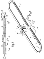
- Cable transportation system 1 indicates a cable transportation system for passenger transport.
- Cable transportation system 1 comprises a fixed structure 2 ( Figure 2 ) for supporting a pair of parallel rails 3 defining an endless transportation path P; a continuous draw cable 4 extending along transportation path P; a drive station 5 for driving draw cable 4; a number of vehicles 6 (only one shown in Figure 1 ) movable along transportation path P and connectable selectively to draw cable 4; and a number of passenger stations 7 (only one shown in Figure 1 ) where each vehicle 6 is stopped cyclically to allow passengers to board and alight from vehicle 6.
- Passenger station 7 comprises a deceleration portion 7a, of length D, where vehicle 6 is decelerated; a stop position 7b, where vehicle 6 is stopped; and an acceleration portion 7c, of length A, where vehicle 6 is accelerated.
- fixed structure 2 is anchored to a base 8, and provides for supporting rails 3, guiding draw cable 4 by means of guide rollers 9 and 10, and supporting a pair of runners 11 extending at passenger station 7, and which cooperate with vehicle 6 to connect and release vehicle 6 to and from draw cable 4.
- Each rail 3 has a top supporting face 12 and an inner lateral supporting face 13.
- the two runners 11 extend along path P, between the two rails 3, at deceleration portion 7a and acceleration portion 7c, as described in Patent EP 0687 607 B1 .
- the stop position 7b separating deceleration portion 7a and acceleration portion 7c is defined with a narrow tolerance of about 20 cm.
- Drive station 5 comprises a winch 14 of axis A1; and an electric motor 15 for rotating winch 14 about axis A1 continuously at constant speed, and moving draw cable 4 at constant speed along path P.
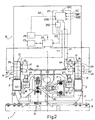
- vehicle 6 comprises a frame 16; a number of supporting wheels 17; a number of direction wheels 18; a cab 19 on top of frame 16; and a coupling device 20 for connection to draw cable 4.
- Coupling device 20 is of the type described in Patent EP 0687 607 B1 , and cooperates with the two runners 11 at each passenger station 7 as described in Patent EP 0687 607 B1 .
- vehicle 6 For each supporting wheel 17, vehicle 6 comprises an electric machine 21, which acts as a generator, motor, and brake. Vehicle 6 comprises a selector 22 for modulating electric power flow; an electric power accumulator 23; an electric user device 24; and a control unit 25, in turn comprising a computing module 25B and a regulating module 25C.
- Each wheel 17 is directional, rotates about a horizontal axis A2, and comprises a tyre 26 resting on the top supporting face 12 of a rail 3; and each direction wheel 18 rotates about a vertical axis A3, is forced against the inner lateral supporting face 13 of a rail 3 by elastic members not shown, and is fitted to a movable arm 27 connected to a respective wheel 17, and which imparts a steering moment to wheel 17, depending on the position of direction wheel 18.
- This method of orienting wheels 17 is made possible by axis A3 of direction wheel 18 and axis A2 of respective wheel 17 lying in different planes.
- each wheel 17 comprises a hub 28 supporting a wheel rim 29, in turn supporting tyre 26, and is mounted to rotate about a pin 30 connected to arm 27 and hinged to frame 16 about a steering axis A4.
- a rolling bearing 31 is interposed between pin 30 and hub 28.
- Hub 28 comprises an annular portion 32 projecting on the opposite side to frame 16, and in which is formed a seat for the rotor 33 of electric machine 21.
- Each wheel 17 has a cover 35 formed by two connected flanges 36 and 37, which enclose an annular stator 38 of electric machine 21. Cover 35 is fixed to pin 30, and provides for supporting stator 38 and protecting electric machine 21 from the surrounding environment.
- Stator 38 comprises a core 39 of ferromagnetic material, and an electric winding 40 supported by core 39.
- the rotor extends about the stator.
- vehicle 6 comprises a brake 41 at each wheel 17; and a speed sensor 42, which transmits a speed signal SV, related to the instantaneous speed of vehicle 6, to control unit 25.
- Cable transportation system 1 generates electric power when vehicle 6 is moving, and uses the generated electric power to power user device 24, which indicates as a whole one or more user devices, such as an interior lighting system of vehicle 6, and exterior lighting system of vehicle 6, a heating system of vehicle 6, an air-conditioning system of vehicle 6, etc..
- User device 24 also represents as a whole a group of different user devices in general, and supplies an absorption signal SA to computing module 25B.
- electric machines 21 at respective wheels 17 generate electric power which is stored in accumulator 23 by means of selector 22; and accumulator 23 powers user device 24, as required, by means of selector 22 and under the control of control unit 25 which coordinates operation of selector 22.
- Electric machines 21 operate as generators along the whole of transportation path P, with the exception of the portions at passenger station 7, where control unit 25 operates electric machines 21 as generators, motors, and brakes, depending on circumstances.
- Electric machines 21 on board vehicle 6, and brakes 41 eliminate the need to install, at each passenger station 7, the deceleration and acceleration conveyors described in Patent EP 0 687 607 B1 .
- vehicle 6 is decelerated as follows : once the draw cable is detached from vehicle 6, vehicle 6 is braked by electric machines 21, which absorb power by operating as electric power generators, and by the normal rolling friction of wheels 17 and direction wheels 18 on rails 3. These braking forces, however, do not guarantee stoppage of vehicle 6 at stop position 7b and at the required speed. Moreover, the mass of vehicle 6 varies, depending on the number of passengers; and other uncontrollable parameters, such as external temperature and humidity, may also affect the forces in play when decelerating vehicle 6.
- computing module 25B receives speed signal SV from sensor 42, and compares speed signal SV with a deceleration speed curve SVD corresponding to the ideal deceleration speed, as a function of time, from the start of deceleration portion 7a to stop position 7b. Whenever speed signal SV exceeds the ideal speed, according to deceleration speed curve SVD, by more than a given acceptance range, control unit 25 transmits an instantaneous actuating signal F1 to brakes 41.
- regulating module 25C Under the control of computing module 25B, emits an actuating signal F2 to instantaneously operate at least one electric machine 21 as a motor.
- the instantaneous speed SV of vehicle 6 is compared repeatedly with deceleration speed curve SVD and acceleration speed curve SVA, and, by means of successive adjustments, control unit 25 guides vehicle 6 into stop position 7b. Once the passengers have alighted or boarded, vehicle 6 is ready to depart.
- vehicle 6 is braked solely by electric machines 21 operating as brakes. That is, when speed SV of vehicle 6 is greater than deceleration speed SVD, regulating module 25C, in accordance with instructions from computing module 25B, transmits a signal F2 to selector 22, which increases the electric absorption, and hence the braking force, of electric machines 21. Regulating the braking force of electric machines 21 allows brakes 41 to be omitted. Alternatively, electric machines 21 brake vehicle 6 together with brakes 41.
- electric machines 21 may be used to advantage as emergency brakes : computing unit 25B is supplied by the control system (not shown) of cable transportation system 1 with a signal SRC relating to the integrity of draw cable 4.
- signal SRC assumes a value indicating failure of draw cable 4
- the computing module transmits a signal to regulating module 25C, which, by means of signal F2, sets selector 22 to maximum absorption (resistance) to enable electric machines 21 as brakes - in this case, as emergency brakes.
- selector 22 can be operated as a power dissipater.
- the start signal to start vehicle 6 is received by control unit 25 from the control system (not shown) of cable transportation system 1; and, on receiving the start signal, control unit 25 commands selector 22 to power all the electric machines 21 as motors.
- computing module 25B compares vehicle speed SV with an ideal acceleration speed curve SVA, calculated as a function of the speed SC of the cable, and accelerates or decelerates vehicle 6 by adjusting power supply to electric machines 21, depending on the deviation of speed signal SV with respect to acceleration speed curve SVA and the relative acceptance range. Vehicle 6 is thus brought to substantially the same speed as speed SC of draw cable 4 by the end of portion 7c, and can therefore be connected smoothly to draw cable 4.
- the power supplied on board vehicle 6 is substantially that transmitted to draw cable 4 in the form of kinetic energy at drive station 5 and temporarily stored in accumulator 23 for use in accelerating vehicle 6.
- This power is supplied to user device 24, fed back to wheels 17 as drive power, and, if necessary, dissipated when operating electric machine 21 as a brake.
- number 43 indicates a passenger "to-and-fro" cable transportation system, which comprises two parallel rails 44 defining a straight transportation path P1; a continuous draw cable 45 extending along transportation path P1; a drive station 46 for driving draw cable 45; a vehicle 47 movable along transportation path P1 and connected to draw cable 45; and two passenger stations 48 located at opposite ends of transportation path P1, and where vehicle 47 is stopped to allow passengers to board and alight from vehicle 47.
- Drive station 46 comprises a winch 49 of axis A5; and an electric motor 50 for rotating winch 49 about axis A5, and moving draw cable 45 along path P1. Vehicle 47 is reversed and stopped at passenger stations 48 by winch 49.
- Vehicle 47 is equipped with an electric machine 21 of the type described with reference to the first embodiment of the invention, and which acts as a current generator, and, in the event of failure of draw cable 45, as an emergency brake and as a motor to return vehicle 47 to passenger station 48.
- the component parts are substantially the same as in the first embodiment, and operation differs solely as regards selective connection to the draw cable.
Landscapes
- Engineering & Computer Science (AREA)
- Mechanical Engineering (AREA)
- Transportation (AREA)
- Life Sciences & Earth Sciences (AREA)
- Sustainable Development (AREA)
- Sustainable Energy (AREA)
- Power Engineering (AREA)
- Electric Propulsion And Braking For Vehicles (AREA)
- Load-Engaging Elements For Cranes (AREA)
- Ropes Or Cables (AREA)
- Platform Screen Doors And Railroad Systems (AREA)
- Electric Cable Arrangement Between Relatively Moving Parts (AREA)
Claims (12)
- Seiltransportsystem (1), das umfasst: Schienen (3; 44) und ein Zugseil (4; 45), die sich beide entlang eines Transportwegs (P; P1) erstrecken; ein Antriebselement (15; 50) zum Antreiben des Zugseils (4; 45); wenigstens ein Fahrzeug (6; 47), das sich entlang des Transportwegs (P; P1) bewegt und einen Rahmen (16) umfasst; eine Anzahl von Tragrädern (17), die entlang der Schienen (3; 44) rollen, eine Kopplungsvorrichtung (20) zum Verbinden des Fahrzeugs (6; 47) mit dem Zugseil (4; 45), eine Anzahl von Lenkrädern (18); und eine Kabine (19) über dem Rahmen (16); und wenigstens eine Fahrgaststation (7; 48), wo das Fahrzeug (6; 47) gestoppt wird; wobei das Fahrzeug (6; 47) eine elektrische Maschine umfasst, um an Bord des Fahrzeugs (6; 47) elektrische Leistung zu erzeugen; wobei das System dadurch gekennzeichnet ist, dass die elektrische Maschine (21) einen Stator und einen Rotor, der von den Tragrädern (17) angetrieben wird, umfasst, und das Fahrzeug (6; 47) eine Anzahl elektrischer Maschinen (21) umfasst, von denen jede ein Rad (17) hält, das eine Nabe (28) umfasst, die eine Radfelge (29) hält, die wiederum einen Reifen (26) hält, und derart montiert ist, dass es sich um einen Stift (30) dreht, der mit dem Arm (27) verbunden ist und an dem Rahmen (16) um eine Lenkachse (A4) gelenkig befestigt ist; wobei jede elektrische Maschine (21) an die Nabe (28) eines entsprechenden Tragrads (17) angebaut ist, und wobei die Nabe (28) des Tragrads (17) sich um den Stift (30) dreht und den Rotor (33) der elektrischen Maschine (21) hält.
- System nach Anspruch 1, dadurch gekennzeichnet, dass das Fahrzeug (6; 47) einen Akkumulator (23) zum Speichern der von den elektrischen Maschinen (21) erzeugten elektrischen Leistung umfasst.
- System nach Anspruch 1, dadurch gekennzeichnet, dass das Fahrzeug (6; 47) wenigstens eine Benutzervorrichtung (24) umfasst, die mit der elektrischen Leistung betrieben wird, die von den elektrischen Maschinen (21) erzeugt wird.
- System nach einem der vorhergehenden Ansprüche, dadurch gekennzeichnet, dass die elektrischen Maschinen (21) reversibel sind und ein Antriebsdrehmoment an wenigstens ein Tragrad (17) liefern.
- System nach einem der vorhergehenden Ansprüche, dadurch gekennzeichnet, dass ein Selektor (22) mit dem Akkumulator (23) verbunden ist, um den elektrischen Leistungsfluss zu und von den elektrischen Maschinen (21), dem Akkumulator (23) und der Benutzervorrichtung (24) zu regulieren.
- Verfahren zum Antreiben eines Seiltransportsystems (1; 43), das umfasst: Vorrücken eines Fahrzeugs (6; 47), das mit einer Anzahl von Tragrädern (17) ausgerüstet ist, die auf Schienen (3; 44) ruhen, welche sich entlang eines Transportwegs (P; P1) erstrecken, und das einen Rahmen (16), eine Kopplungsvorrichtung (20) zum Verbinden des Fahrzeugs (6; 47) mit einem Zugseil (4; 45), eine Anzahl von Lenkrädern (18); und eine Kabine (19) über dem Rahmen (16) umfasst; Antreiben des Fahrzeugs (6; 47) mittels eines Zugseils (4; 45), das sich entlang des Transportwegs (P; P1) erstreckt und von einem Antriebselement (15; 50) angetrieben wird; Stoppen des Fahrzeugs (6; 47) an wenigstens einer Fahrgaststation (7; 48), die entlang des Transportwegs (P; P1) angeordnet ist; und Antreiben einer elektrischen Maschine (21), um an Bord des Fahrzeugs (6; 47) elektrische Leistung zu erzeugen; wobei das Verfahren dadurch gekennzeichnet ist, dass eine Anzahl elektrischer Maschinen (21) mittels der Tragräder (17) des Fahrzeugs (6; 47) angetrieben wird und jedes Tragrad (17) eine Nabe (28) umfasst, die eine Radfelge (29) hält, die wiederum einen Reifen (26) hält, und derart montiert ist, dass es sich um einen Stift (30) dreht, der mit dem Arm (27) verbunden ist und an dem Rahmen (16) um eine Lenkachse (A4) gelenkig befestigt ist; wobei jede elektrische Maschine (21) an die Nabe (28) eines entsprechenden Rads (17) angebaut ist, und wobei die Nabe (28) des Rads (17) sich um den Stift (30) dreht und den Rotor (33) der elektrischen Maschine (21) hält; wobei das Verfahren den Betrieb jeder elektrischen Maschine (21) als ein Generator, ein Motor und eine Bremse umfasst.
- Verfahren nach Anspruch 6, dadurch gekennzeichnet, dass elektrische Leitung in einem Akkumulator (23) an Bord des Fahrzeugs (6; 47) gespeichert wird.
- Verfahren nach Anspruch 6 oder 7, gekennzeichnet durch die Leistungsversorgung wenigstens einer Benutzervorrichtung (24) an Bord des Fahrzeugs (6; 47) mit der elektrischen Leistung, die von den elektrischen Maschinen (21) erzeugt wird.
- Verfahren nach Anspruch 6 oder 7, wobei das Fahrzeug (6; 47) selektiv von dem Zugkabel (4; 45) trennbar ist; wobei das Verfahren durch die Lieferung der in dem Akkumulator (23) gespeicherten elektrischen Leistung an die elektrischen Maschinen (21), um wenigstens eines der Räder (17) mit Leistung zu versorgen, gekennzeichnet ist.
- Verfahren nach einem der Ansprüche 6 bis 9, gekennzeichnet durch Ausgeben eines Geschwindigkeitssignals (SV) in Bezug auf die Geschwindigkeit des Fahrzeugs (6) mittels eines Geschwindigkeitssensors (42); Vergleichen des Geschwindigkeitssignals (SV) mit einer Verlangsamungsgeschwindigkeitskurve (SVD), die der idealen Verlangsamungsgeschwindigkeit als eine Funktion der Zeit entlang eines Verlangsamungsabschnitts (7a) des Transportwegs (P) entspricht; und Ausgeben eines ersten Betätigungssignals (F1), um immer dann unverzüglich die Bremse (21; 41; 21, 41) zu betätigen, wenn das Geschwindigkeitssignal (SV) die Verlangsamungsgeschwindigkeitskurve (SVD) um mehr als einen gegebenen Akzeptanzbereich überschreitet.
- Verfahren nach einem der Ansprüche 6 bis 9, gekennzeichnet durch Ausgeben eines Geschwindigkeitssignals (SV) in Bezug auf die Geschwindigkeit des Fahrzeugs (6) mittels eines Geschwindigkeitssensors (42); Vergleichen des Geschwindigkeitssignals (SV) mit einer Verlangsamungsgeschwindigkeitskurve (SVD), die der idealen Verlangsamungsgeschwindigkeit als eine Funktion der Zeit entlang eines Verlangsamungsabschnitts (7a) des Transportwegs (P) entspricht; und Ausgeben eines zweiten Betätigungssignals (F2), um immer dann die elektrische Leistungsversorgung an die elektrischen Maschinen (21) zu regulieren, wenn das Geschwindigkeitssignal (SV) um mehr als einen gegebenen Akzeptanzbereich unter die Verlangsamungsgeschwindigkeitskurve (SVD) fällt.
- Verfahren nach einem der Ansprüche 6 bis 9, gekennzeichnet durch Ausgeben eines Geschwindigkeitssignals (SV) in Bezug auf die Geschwindigkeit des Fahrzeugs (6) mittels eines Geschwindigkeitssensors (42); Vergleichen des Geschwindigkeitssignals (SV) mit einer Beschleunigungsgeschwindigkeitskurve (SVA), die der idealen Beschleunigungsgeschwindigkeit als eine Funktion der Zeit entlang eines Beschleunigungsabschnitts (7c) des Transportwegs (P) entspricht, mittels einer Steuereinheit (25); und Ausgeben eines zweiten Betätigungssignals (F2), um immer dann die elektrische Leistungsversorgung an die elektrischen Maschinen (21) zu regulieren, wenn das Geschwindigkeitssignal (SV) um mehr als einen gegebenen Akzeptanzbereich von der Beschleunigungsgeschwindigkeitskurve (SVA) abweicht.
Applications Claiming Priority (2)
| Application Number | Priority Date | Filing Date | Title |
|---|---|---|---|
| IT000835A ITMI20070835A1 (it) | 2007-04-20 | 2007-04-20 | Impianto di trasporto a fune e metodo di azionamento dello stesso |
| PCT/EP2008/054774 WO2008129019A1 (en) | 2007-04-20 | 2008-04-18 | Rail transportation system with releasable haulage cable and relative drive method |
Publications (3)
| Publication Number | Publication Date |
|---|---|
| EP2148801A1 EP2148801A1 (de) | 2010-02-03 |
| EP2148801B1 EP2148801B1 (de) | 2012-03-21 |
| EP2148801B2 true EP2148801B2 (de) | 2019-09-25 |
Family
ID=39673202
Family Applications (1)
| Application Number | Title | Priority Date | Filing Date |
|---|---|---|---|
| EP08736407.1A Active EP2148801B2 (de) | 2007-04-20 | 2008-04-18 | Schienentransportsystem mit lösbarem zugseil und verwandtes antriebsverfahren |
Country Status (7)
| Country | Link |
|---|---|
| US (2) | US8844446B2 (de) |
| EP (1) | EP2148801B2 (de) |
| AT (1) | ATE550237T2 (de) |
| ES (1) | ES2383625T5 (de) |
| IT (1) | ITMI20070835A1 (de) |
| PT (1) | PT2148801E (de) |
| WO (1) | WO2008129019A1 (de) |
Families Citing this family (26)
| Publication number | Priority date | Publication date | Assignee | Title |
|---|---|---|---|---|
| ITBZ20030005A1 (it) | 2003-01-30 | 2004-07-31 | High Technology Invest Bv | Dispositivo pressore per la conduzione di fune in sistemi di trasporto a trazione di fune. |
| ITBZ20050051A1 (it) | 2005-09-29 | 2007-03-30 | High Technology Invest Bv | Dispositivo antiscarrucolamento per funi di impianti funiviari. |
| ITMI20070157U1 (it) | 2007-04-20 | 2008-10-21 | Rolic Invest Sarl | Seggiovia |
| ITMI20071618A1 (it) | 2007-08-03 | 2009-02-04 | Rolic Invest Sarl | Impianto di trasporto a fune e metodo di azionamento dello stesso |
| ITMI20072071A1 (it) | 2007-10-26 | 2009-04-27 | Rolic Invest Sarl | Impianto di trasporto a fune e metodo di azionamento dello stesso |
| IT1395098B1 (it) | 2009-07-09 | 2012-09-05 | Rolic Invest Sarl | Unita' di trasporto per impianti di trasporto a fune |
| IT1395737B1 (it) | 2009-08-04 | 2012-10-19 | Rolic Invest Sarl | Dispostivo di richiamo di un sedile per skilift |
| IT1401120B1 (it) | 2010-07-14 | 2013-07-12 | Rolic Invest Sarl | Scambio per impianto di trasporto a fune e impianto di trasporto a fune comprendente tale scambio. |
| AT512298B1 (de) | 2012-02-06 | 2013-07-15 | Innova Patent Gmbh | Rolle, insbesondere laufrolle bzw. tragrolle für seilbahnanlagen |
| FR2993227B1 (fr) * | 2012-07-10 | 2015-10-30 | Pomagalski Sa | Installation de transport par cable |
| ITMI20130309A1 (it) | 2013-02-28 | 2014-08-29 | Rolic Internat S A R L | Impianto di trasporto a fune per avanzare unita' di trasporto lungo un tracciato determinato |
| ITMI20130308A1 (it) | 2013-02-28 | 2014-08-29 | Rolic Internat S A R L | Scambio per un impianto di trasporto a fune |
| ITMI20130609A1 (it) * | 2013-04-12 | 2014-10-13 | Rolic Internat S A R L | Carrello per impianti di trasporto a fune e impianto di trasporto a fune comprendente tale carrello |
| ITMI20130741A1 (it) | 2013-05-07 | 2014-11-08 | Rolic Internat S A R L | Impianto di trasporto a fune per avanzare unita' di trasporto lungo un tracciato determinato |
| TW201525283A (zh) * | 2013-12-30 | 2015-07-01 | 鈞富綠能股份有限公司 | 循環發電裝置 |
| WO2015166357A1 (en) | 2014-05-02 | 2015-11-05 | Dimensione Ingenierie S.R.L. | A continuously moving cableway |
| AT516963B1 (de) | 2015-03-19 | 2016-10-15 | Innova Patent Gmbh | Anlage zur Versorgung mindestens eines elektrischen Verbrauchers bzw. eines Energiespeichers mit Gleichstrom |
| EP3504095B1 (de) | 2016-08-25 | 2021-11-24 | Kinkead, Jordan | Schienentransportsystem |
| FR3069512B1 (fr) * | 2017-07-27 | 2019-08-23 | Vinci Construction | Installation de transport a cable ou analogue, et vehicule adapte a une telle installation |
| CA3028449A1 (en) * | 2017-12-22 | 2019-06-22 | Leitner S.P.A. | Cable transportation system and method for transporting people or goods and clamp for a vehicle of a cable transportation system |
| US10784744B2 (en) * | 2018-08-10 | 2020-09-22 | Russell Wayne Crawford | Gravity line power generation system including an overhead trolley mechanism to harvest kinetic energy from a wheeled vehicle moving down a slope |
| EP3978302A1 (de) * | 2020-10-01 | 2022-04-06 | Bartholet Maschinenbau AG | Seilbahnanlage und verfahren zum betreiben einer seilbahnanlage |
| CA3239016A1 (en) * | 2021-11-29 | 2023-06-01 | Faycal Chaabi | Transportation systems |
| US11565884B1 (en) | 2021-12-01 | 2023-01-31 | Cooley Enterprises, LLC | Clean energy integrated transportation system using a track and cable |
| US11827249B2 (en) | 2021-12-01 | 2023-11-28 | Cooley Enterprises, LLC | Clean energy integrated transportation system using a hydro system |
| US11390470B1 (en) * | 2021-12-01 | 2022-07-19 | Cooley Enterprises, LLC | Clean energy integrated transportation system |
Citations (7)
| Publication number | Priority date | Publication date | Assignee | Title |
|---|---|---|---|---|
| DE1588622A1 (de) † | 1967-05-03 | 1970-05-21 | Pintsch Bamag Ag | Schleifringloser Generator zur Steuerung von Hilfseinrichtungen eines Fahrzeuges |
| GB1242749A (en) † | 1967-08-25 | 1971-08-11 | George Crompton | Electrically driven locomotive |
| CH564445A5 (en) † | 1973-07-20 | 1975-07-31 | Vevey Atel Const Mec | Electrical generator used on railway carriages - is assembled in annular space between wheel and axle uses permanent magnet |
| US5465806A (en) † | 1989-03-31 | 1995-11-14 | Kabushiki Kaisha Shikoku Sogo Kenkyujo | Electric vehicle |
| DE19756904A1 (de) † | 1996-12-20 | 1998-06-25 | Whitaker Corp Wilmington | Elektrische Leistungsvorrichtung zur Anbringung an einer Achse |
| EP1088729B1 (de) † | 1999-10-01 | 2005-04-20 | High Technology Investments B.V. | Zwangsgeführtes Nahverkehrssystem |
| DE102006040220A1 (de) † | 2006-08-28 | 2008-03-20 | Franc Just | Radnabenmotor |
Family Cites Families (91)
| Publication number | Priority date | Publication date | Assignee | Title |
|---|---|---|---|---|
| US472211A (en) * | 1892-04-05 | Half to louis a | ||
| DE423865C (de) | 1925-02-28 | 1926-01-12 | Karl Laissle Dipl Ing | Seiltragevorrichtung |
| US1944446A (en) * | 1932-05-27 | 1934-01-23 | Mckay Co | Swing |
| FR891743A (fr) | 1941-11-25 | 1944-03-17 | Pohlig J Ag | Commande pour téléfériques |
| FR913146A (fr) | 1945-08-06 | 1946-08-29 | Téléphérique à bennes multiples, à marche continue, pour voyageurs | |
| CH259291A (de) | 1947-02-21 | 1949-01-15 | Eisen Und Stahlwerke Oehler & | Sicherheitseinrichtung an Schwebebahnanlagen. |
| US2662587A (en) * | 1949-11-18 | 1953-12-15 | Mcilvaine Alexander | Chair for aerial skilifts |
| FR1100001A (fr) | 1954-02-19 | 1955-09-15 | Perfectionnements aux transporteurs aériens | |
| US2710650A (en) * | 1954-03-19 | 1955-06-14 | Riblet Tramway Company | Aerial ski lift chair |
| US2985224A (en) * | 1958-03-28 | 1961-05-23 | Riblet Tramway Company | Aerial lift passenger chair |
| FR1199721A (fr) | 1958-06-20 | 1959-12-16 | Perfectionnements aux transporteurs aériens à câble | |
| CH360704A (fr) | 1960-03-15 | 1962-03-15 | Mayor Henry | Dispositif de sécurité pour un câble de transporteurs aériens |
| US3170412A (en) * | 1963-05-06 | 1965-02-23 | Ribiet Tramway Company | Chair swing damper |
| FR1423648A (fr) | 1963-05-10 | 1966-01-07 | Doppelmayr & Sohn | Dispositif de sécurité pour téléphériques, notamment pour téléphériques monocâbles |
| GB1326264A (en) | 1969-10-29 | 1973-08-08 | Krampe Co Fertigund In Bergbau | Railway track and vehicles for use in underground mining |
| DE2020746C3 (de) | 1970-04-28 | 1979-03-08 | Fritz 6685 Schiffweiler Leh | Seilführungsstation für schienengebundene Flurförderwagen |
| AT315910B (de) | 1970-08-21 | 1974-06-25 | Waagner Biro Ag | Zugseilschwingungsdämpfer |
| DE2101743A1 (de) | 1971-01-15 | 1972-09-07 | Maschinenfabrik Scharf Gmbh, 4700 Hamm | Rollenbock mit einer gesteuerten Zwangsführung für das Zugseil einer insbesondere in Förderstrecken des Bergbaus verlegten Seilbahn |
| CH554761A (de) | 1972-11-03 | 1974-10-15 | Streiff Mathias | Vorrichtung zum befestigen von zugseiltragrollen, fahrund/oder fuehrungsschienen und treppen an rampe von standseilbahnen. |
| CH563902A5 (de) * | 1973-11-20 | 1975-07-15 | Habegger Willy | |
| GB1460106A (en) * | 1974-05-22 | 1976-12-31 | Coal Industry Patents Ltd | Method of propulsion of vehicles |
| FR2340895A1 (fr) | 1976-02-12 | 1977-09-09 | Pomagalski Sa | Dispositif de support et de guidage d'un cable aerien |
| AT342655B (de) | 1976-06-14 | 1978-04-10 | Waagner Biro Ag | Zugseilschwingungsdampfer fur seilforderanlagen |
| JPS5810264B2 (ja) * | 1976-08-31 | 1983-02-24 | 日産自動車株式会社 | 架空索道システムにおける車両の走行安定機構 |
| FR2387830A1 (fr) | 1977-04-22 | 1978-11-17 | Pomagalski Sa | Dispositif de securite surveillant l'integrite des elements d'appui du cable d'un balancier d'une telecabine ou d'un telesiege |
| FR2416148A1 (fr) * | 1978-02-01 | 1979-08-31 | Pomagalski Sa | Dispositif de securite pour un balancier de support d'un cable aerien d'une installation de transport |
| FR2392858A1 (fr) | 1977-05-12 | 1978-12-29 | Mautino Victor | Ensemble support a galets pour cable d'installation de transport aerien par monocable porteur-tracteur |
| FR2391450A1 (fr) | 1977-05-18 | 1978-12-15 | Stgm | Procede et dispositif de controle de position d'un cable par rapport a un guide roulant |
| US4470355A (en) * | 1977-11-14 | 1984-09-11 | Kunczynski Jan K | Pneumatic cable tensioning apparatus and method for an aerial tramway or the like |
| DE2811336A1 (de) | 1978-03-16 | 1979-09-20 | Scharf Gmbh Maschf | Zugseilbetriebene transportbahn |
| US4226187A (en) * | 1978-10-23 | 1980-10-07 | Sdi Welding Corporation | Ski lift apparatus and safety device |
| JPS5599456A (en) * | 1979-01-25 | 1980-07-29 | Nissan Motor | Suspension mechanism of aerial track car |
| FR2496579A1 (fr) | 1980-12-22 | 1982-06-25 | Pomagalski Sa | Telepherique bicable |
| DE3109294A1 (de) | 1981-03-11 | 1982-10-14 | Muckenhaupt GmbH, 4320 Hattingen | Seilgezogene transportbahn fuer den untertaegigen grubenbetrieb |
| DE3109944C2 (de) * | 1981-03-14 | 1984-02-02 | PHB Weserhütte AG, 5000 Köln | Kuppelbare Umlauf-Drahtseilbahn zur Beförderung von Material, wie Schüttgut |
| AT373832B (de) | 1981-04-21 | 1984-02-27 | Nejez Josef Dipl Ing Dr Techn | Sicherheitseinrichtung fuer die ueberwachung der seillage von geerdeten foerderseilen auf rollenbatterien von seilbahnen und schleppliften |
| US4462314A (en) * | 1982-02-05 | 1984-07-31 | Kunczynski Jan K | Rocker arm assembly for an aerial tramway |
| CH656357A5 (fr) * | 1983-07-04 | 1986-06-30 | Vevey Atel Const Mec | Vehicule motorise suspendu. |
| IT8322994U1 (it) | 1983-09-16 | 1985-03-16 | Leitner Spa | Freno centrifugo per dispositivo di traino ad azione progressiva per sciovie. |
| FR2562857B1 (fr) * | 1984-04-13 | 1987-01-16 | Pomagalski Sa | Balanciers d'une installation de transport a cable aerien |
| AT385480B (de) | 1985-09-11 | 1988-04-11 | Doppelmayr & Sohn | Laufwerkstraeger fuer seilbahnen, insbesondere fuer einseil-umlaufbahnen |
| US4671187A (en) * | 1985-09-20 | 1987-06-09 | Kunczynski Jan K | Deropement sensor apparatus with gravity-biased, falling, magnetic member |
| IT206251Z2 (it) | 1985-10-09 | 1987-07-13 | Leitner Spa | Guida di invito ammortizzato per veicoli funiviari. |
| FR2604675B1 (fr) * | 1986-10-02 | 1988-12-30 | Pomagalski Sa | Installation de transport aerien a deux cables porteurs-tracteurs a poulies decalees |
| IT1207747B (it) | 1987-03-06 | 1989-06-01 | Lettner S P A | Impianto teleferico con deviazione del persorso della fune traente. |
| FR2612144B1 (fr) * | 1987-03-11 | 1991-09-06 | Pomagalski Sa | Installation de transport aerien a deux cables porteurs-tracteurs a poulies decalees verticalement |
| DE3834116A1 (de) | 1987-11-04 | 1989-05-24 | Scharf Gmbh Maschf | Anordnung zur fuehrung eines zugseils |
| AT388146B (de) | 1988-01-08 | 1989-05-10 | Engel Edwin Dipl Ing Dr Techn | Verfahren und vorrichtungen zur selbsttaetigen ueberwachung der lage der foerderseile von seilbahnen und schleppliften auf einer seiltragrolle |
| AT390926B (de) | 1989-03-14 | 1990-07-25 | Swoboda Seilbahnbau Gmbh | Vorrichtung zum ueberwachen der lage eines foerderseiles einer seilbahn oder eines schleppliftes auf einer seilrolle |
| DE3927757C1 (en) | 1989-08-23 | 1991-03-28 | Kloeckner-Becorit Gmbh, 4620 Castrop-Rauxel, De | Wagon rope haulage system - uses single flange rollers on spring-loaded levers |
| AT393479B (de) * | 1990-03-08 | 1991-10-25 | Waagner Biro Ag | Verbindung von seilbahnwagen |
| FR2670452A1 (fr) | 1990-12-18 | 1992-06-19 | Pomagalski Sa | Dispositif amortisseur des oscillations du cable tracteur d'un telepherique. |
| FR2670451A1 (fr) | 1990-12-18 | 1992-06-19 | Pomagalski Sa | Telecabine ou telesiege debrayage a deux boucles de cable. |
| US5113768A (en) * | 1991-03-15 | 1992-05-19 | Brown Garrett W | Cable-suspended apparatus for supporting a stabilized camera assembly |
| FR2676981B1 (fr) | 1991-06-03 | 1993-08-27 | Pomagalski Sa | Dispositif de securite d'une installation de transport a cable aerien. |
| DE4127373A1 (de) * | 1991-08-19 | 1993-02-25 | Wolf Von Bodisco | Schwebebahn an einer schiene haengend |
| WO1993011015A1 (fr) | 1991-11-29 | 1993-06-10 | Seiko Epson Corporation | Deplacement dans un appareil de transfert et controleur d'entrainement de l'element de transfert |
| FR2706404A1 (fr) | 1993-06-09 | 1994-12-23 | Montagner Rene | Installation de téléski. |
| FR2709278B1 (fr) * | 1993-08-25 | 1995-10-27 | Pomagalski Sa | Dispositif de stabilisation des pinces d'un téléporteur. |
| CA2143504A1 (en) * | 1994-03-11 | 1995-09-12 | Ernst Egli | Rope guide system for an aerial ropeway, particularly a circuital aerial ropeway |
| FR2719011B1 (fr) * | 1994-04-22 | 1996-07-12 | Pomagalski Sa | Installation de transport à câble tracteur et à moteur embarqué. |
| IT1270233B (it) * | 1994-06-16 | 1997-04-29 | Leitner Spa | Morsa del tipo a doppia azione per il vincolo alla fune traente di un veicolo funicolare |
| IT1270234B (it) | 1994-06-16 | 1997-04-29 | Leitner Spa | Impianto funicolare a rotaia e fune traente, in particolare per il trasporto urbano, del tipo in cui i veicoli sono dotati di morsa a ganasce mobili per l'agganciamento/sganciamento da detta fune traente |
| IT1276268B1 (it) | 1994-07-14 | 1997-10-28 | Hoelzl Costruzione Funivie Srl | Sistema di movimentazione per impianti funiviari a due o rispettivamente una via di corsa e presentante funi portanti o funi |
| AT403147B (de) | 1995-05-29 | 1997-11-25 | Girak Garaventa Gmbh | Mechanischer seilentgleisungsschutz |
| CA2311673C (en) * | 1997-11-26 | 2009-02-17 | Litens Automotive Partnership | Load sensor having an annular gauge ring |
| EP0970864B1 (de) | 1998-07-09 | 2003-12-03 | Ropetrans AG | Haltevorrichtung für ein Tragseil |
| IT1313108B1 (it) | 1999-08-18 | 2002-06-17 | Leitner Spa | Morsa a ganasce mobili perfezionata per l'aggancio e lo sgancio diveicoli ad una fune traente di un impianto di trasporto |
| IT1310249B1 (it) * | 1999-09-24 | 2002-02-11 | Leitner Spa | Rulliera a doppio effetto per sostegni d'impianti a monofune, inparticolare seggiovie e cabinovie. |
| IT1316116B1 (it) * | 2000-01-21 | 2003-03-28 | Leitner Spa | Dispositivo per la impostazione e regolazione automatica della forzadi trazione di una fune di un verricello sopratesta per una macchina |
| AT409253B (de) | 2000-07-20 | 2002-07-25 | Innova Patent Gmbh | Anlage zur beförderung von personen und verfahren zum betrieb einer derartigen anlage |
| US20020043829A1 (en) | 2000-10-04 | 2002-04-18 | Garaventa Holding Ag | Method and arrangement to close a bubble top for a chairlift |
| IT1316148B1 (it) | 2000-11-27 | 2003-03-28 | High Technology Invest Bv | Dispositivo di controrullo per impianti di trasporto a fune ditrazione. |
| IT1316149B1 (it) * | 2000-11-27 | 2003-03-28 | High Technology Invest Bv | Impianto di trasporto a trazione di fune mossa continua con veicolidotati di morse di agganciamento disimpegnabile. |
| US6615118B2 (en) * | 2001-03-27 | 2003-09-02 | General Electric Company | Hybrid energy power management system and method |
| FR2823482A1 (fr) | 2001-04-11 | 2002-10-18 | Pomagalski Sa | Dispositif de support et de guidage pour cable de systeme de transport |
| AT411523B (de) | 2002-01-24 | 2004-02-25 | Innova Patent Gmbh | Sessel für eine seilbahnanlage |
| EP1364853A1 (de) | 2002-05-22 | 2003-11-26 | Pomagalski S.A. | Stütz- und Führungsvorrichtung für das Seil eines Transportsystems |
| EP1419950A1 (de) * | 2002-11-14 | 2004-05-19 | Innova Patent GmbH | Seilbahnanlage mit verdrehbaren Kabinen oder Sesseln |
| ITBZ20030005A1 (it) | 2003-01-30 | 2004-07-31 | High Technology Invest Bv | Dispositivo pressore per la conduzione di fune in sistemi di trasporto a trazione di fune. |
| AT411983B (de) | 2003-03-26 | 2004-08-26 | Edwin Dipl Ing Dr Techn Engel | Beweglicher seilfangschuh |
| ITBZ20030050A1 (it) | 2003-10-03 | 2005-04-04 | High Technology Invest Bv | Smorzatore per funi traenti di funivie. |
| FR2867142B1 (fr) | 2004-03-08 | 2010-09-17 | Pomagalski Sa | Dispositif d'appui et de guidage d'un cable aerien porteur- tracteur au moyen d'un balancier a liaison d'accouplement elastique, et installation de remontee mecanique du type telesiege ou telecabine comportant un tel dispositif |
| ITMI20050800A1 (it) * | 2005-05-03 | 2006-11-04 | Ferruccio Levi | Sistema di movimentazione per impianto funiviario comprendente due funi traenri |
| ITBZ20050051A1 (it) * | 2005-09-29 | 2007-03-30 | High Technology Invest Bv | Dispositivo antiscarrucolamento per funi di impianti funiviari. |
| ITBZ20060036A1 (it) | 2006-08-16 | 2008-02-17 | High Technology Investments Bv | Dispositivo anticaduta per seggiole di seggiovie con dispositivo di comando d'impegno e disimpegno dello sbarramento. |
| ITMI20070157U1 (it) | 2007-04-20 | 2008-10-21 | Rolic Invest Sarl | Seggiovia |
| US7410068B1 (en) * | 2007-07-06 | 2008-08-12 | Agudio S.P.A. | Blondin cableway installation |
| ITMI20071618A1 (it) | 2007-08-03 | 2009-02-04 | Rolic Invest Sarl | Impianto di trasporto a fune e metodo di azionamento dello stesso |
| ITMI20072071A1 (it) | 2007-10-26 | 2009-04-27 | Rolic Invest Sarl | Impianto di trasporto a fune e metodo di azionamento dello stesso |
| EP2075172A1 (de) * | 2007-12-28 | 2009-07-01 | Rolic Invest Sarl | Seilbahnsystem mit Tragkabeln und einem getrennten Zugkabel |
-
2007
- 2007-04-20 IT IT000835A patent/ITMI20070835A1/it unknown
-
2008
- 2008-04-18 AT AT08736407T patent/ATE550237T2/de active
- 2008-04-18 PT PT08736407T patent/PT2148801E/pt unknown
- 2008-04-18 ES ES08736407T patent/ES2383625T5/es active Active
- 2008-04-18 EP EP08736407.1A patent/EP2148801B2/de active Active
- 2008-04-18 US US12/596,801 patent/US8844446B2/en active Active
- 2008-04-18 WO PCT/EP2008/054774 patent/WO2008129019A1/en not_active Ceased
-
2014
- 2014-09-15 US US14/486,657 patent/US9463811B2/en active Active
Patent Citations (7)
| Publication number | Priority date | Publication date | Assignee | Title |
|---|---|---|---|---|
| DE1588622A1 (de) † | 1967-05-03 | 1970-05-21 | Pintsch Bamag Ag | Schleifringloser Generator zur Steuerung von Hilfseinrichtungen eines Fahrzeuges |
| GB1242749A (en) † | 1967-08-25 | 1971-08-11 | George Crompton | Electrically driven locomotive |
| CH564445A5 (en) † | 1973-07-20 | 1975-07-31 | Vevey Atel Const Mec | Electrical generator used on railway carriages - is assembled in annular space between wheel and axle uses permanent magnet |
| US5465806A (en) † | 1989-03-31 | 1995-11-14 | Kabushiki Kaisha Shikoku Sogo Kenkyujo | Electric vehicle |
| DE19756904A1 (de) † | 1996-12-20 | 1998-06-25 | Whitaker Corp Wilmington | Elektrische Leistungsvorrichtung zur Anbringung an einer Achse |
| EP1088729B1 (de) † | 1999-10-01 | 2005-04-20 | High Technology Investments B.V. | Zwangsgeführtes Nahverkehrssystem |
| DE102006040220A1 (de) † | 2006-08-28 | 2008-03-20 | Franc Just | Radnabenmotor |
Also Published As
| Publication number | Publication date |
|---|---|
| EP2148801B1 (de) | 2012-03-21 |
| WO2008129019A1 (en) | 2008-10-30 |
| ES2383625T5 (es) | 2020-09-15 |
| ATE550237T2 (de) | 2012-04-15 |
| EP2148801A1 (de) | 2010-02-03 |
| US20100180792A1 (en) | 2010-07-22 |
| WO2008129019A8 (en) | 2009-11-19 |
| US9463811B2 (en) | 2016-10-11 |
| ITMI20070835A1 (it) | 2008-10-21 |
| US20150000547A1 (en) | 2015-01-01 |
| ES2383625T3 (es) | 2012-06-22 |
| PT2148801E (pt) | 2012-06-01 |
| US8844446B2 (en) | 2014-09-30 |
Similar Documents
| Publication | Publication Date | Title |
|---|---|---|
| EP2148801B1 (de) | Schienentransportsystem mit lösbarem zugseil und verwandtes antriebsverfahren | |
| EP2183142B2 (de) | Kabeltransportsystem und verwandtes betriebsverfahren | |
| US10315886B2 (en) | Electronic safety actuation device with a power assembly, magnetic brake and electromagnetic component | |
| CN100411926C (zh) | 运输系统 | |
| EP3228573B1 (de) | Elektronische sicherheitsvorrichtung mit einer leistungsanordnung | |
| CN110497798B (zh) | 一种联合制动系统及方法 | |
| CN105377663B (zh) | 轨道交通转向架和轨道交通系统 | |
| US20220194742A1 (en) | Elevator system with a climbing counterweight | |
| JP5189774B2 (ja) | 軌道車両の制動エネルギ回収装置および輸送システム | |
| JP6124525B2 (ja) | 索条牽引式輸送設備の救助運転装置 | |
| JP7587864B2 (ja) | 輸送システム | |
| CN111132887B (zh) | 缆绳或类似的运输设备以及适合这种设备的车辆 | |
| CN111347870B (zh) | 一种微轨车辆及其走行装置 | |
| JP3098861B2 (ja) | 地上一次リニアモータ交通システムの運転制御装置 | |
| KR100459973B1 (ko) | 인원 수송장치 | |
| CN120397604B (zh) | 一种电动车架加工的悬挂式输送装置 | |
| CN114929545B (zh) | 用于气力运输系统的动能转换器 | |
| KR20180060632A (ko) | 등속주행 에스컬레이터 | |
| JP4695162B2 (ja) | 輸送装置 | |
| JP6708459B2 (ja) | 索条牽引式輸送設備の運転停止制御方法 | |
| JP2023133866A (ja) | エレベータ | |
| CN121201118A (zh) | 输送系统 | |
| HK40030371A (en) | Cable or similar transport installation, and vehicle suitable for such installation | |
| KR20110133067A (ko) | 정차가 없는 열차운행방법 | |
| JP2011162001A (ja) | 駆動構造、輸送車及び輸送システム |
Legal Events
| Date | Code | Title | Description |
|---|---|---|---|
| PUAI | Public reference made under article 153(3) epc to a published international application that has entered the european phase |
Free format text: ORIGINAL CODE: 0009012 |
|
| 17P | Request for examination filed |
Effective date: 20091120 |
|
| AK | Designated contracting states |
Kind code of ref document: A1 Designated state(s): AT BE BG CH CY CZ DE DK EE ES FI FR GB GR HR HU IE IS IT LI LT LU LV MC MT NL NO PL PT RO SE SI SK TR |
|
| AX | Request for extension of the european patent |
Extension state: AL BA MK RS |
|
| DAX | Request for extension of the european patent (deleted) | ||
| 17Q | First examination report despatched |
Effective date: 20100726 |
|
| GRAP | Despatch of communication of intention to grant a patent |
Free format text: ORIGINAL CODE: EPIDOSNIGR1 |
|
| GRAS | Grant fee paid |
Free format text: ORIGINAL CODE: EPIDOSNIGR3 |
|
| GRAA | (expected) grant |
Free format text: ORIGINAL CODE: 0009210 |
|
| AK | Designated contracting states |
Kind code of ref document: B1 Designated state(s): AT BE BG CH CY CZ DE DK EE ES FI FR GB GR HR HU IE IS IT LI LT LU LV MC MT NL NO PL PT RO SE SI SK TR |
|
| RAP1 | Party data changed (applicant data changed or rights of an application transferred) |
Owner name: ROLIC INVEST S.AR.L. |
|
| REG | Reference to a national code |
Ref country code: GB Ref legal event code: FG4D |
|
| REG | Reference to a national code |
Ref country code: CH Ref legal event code: EP |
|
| REG | Reference to a national code |
Ref country code: IE Ref legal event code: FG4D |
|
| REG | Reference to a national code |
Ref country code: AT Ref legal event code: REF Ref document number: 550237 Country of ref document: AT Kind code of ref document: T Effective date: 20120415 |
|
| REG | Reference to a national code |
Ref country code: DE Ref legal event code: R096 Ref document number: 602008014269 Country of ref document: DE Effective date: 20120516 |
|
| REG | Reference to a national code |
Ref country code: CH Ref legal event code: NV Representative=s name: HEPP WENGER RYFFEL AG |
|
| REG | Reference to a national code |
Ref country code: PT Ref legal event code: SC4A Free format text: AVAILABILITY OF NATIONAL TRANSLATION Effective date: 20120524 |
|
| REG | Reference to a national code |
Ref country code: ES Ref legal event code: FG2A Ref document number: 2383625 Country of ref document: ES Kind code of ref document: T3 Effective date: 20120622 |
|
| REG | Reference to a national code |
Ref country code: NL Ref legal event code: VDEP Effective date: 20120321 |
|
| PG25 | Lapsed in a contracting state [announced via postgrant information from national office to epo] |
Ref country code: NO Free format text: LAPSE BECAUSE OF FAILURE TO SUBMIT A TRANSLATION OF THE DESCRIPTION OR TO PAY THE FEE WITHIN THE PRESCRIBED TIME-LIMIT Effective date: 20120621 Ref country code: HR Free format text: LAPSE BECAUSE OF FAILURE TO SUBMIT A TRANSLATION OF THE DESCRIPTION OR TO PAY THE FEE WITHIN THE PRESCRIBED TIME-LIMIT Effective date: 20120321 Ref country code: LT Free format text: LAPSE BECAUSE OF FAILURE TO SUBMIT A TRANSLATION OF THE DESCRIPTION OR TO PAY THE FEE WITHIN THE PRESCRIBED TIME-LIMIT Effective date: 20120321 |
|
| LTIE | Lt: invalidation of european patent or patent extension |
Effective date: 20120321 |
|
| PG25 | Lapsed in a contracting state [announced via postgrant information from national office to epo] |
Ref country code: LV Free format text: LAPSE BECAUSE OF FAILURE TO SUBMIT A TRANSLATION OF THE DESCRIPTION OR TO PAY THE FEE WITHIN THE PRESCRIBED TIME-LIMIT Effective date: 20120321 Ref country code: GR Free format text: LAPSE BECAUSE OF FAILURE TO SUBMIT A TRANSLATION OF THE DESCRIPTION OR TO PAY THE FEE WITHIN THE PRESCRIBED TIME-LIMIT Effective date: 20120622 Ref country code: FI Free format text: LAPSE BECAUSE OF FAILURE TO SUBMIT A TRANSLATION OF THE DESCRIPTION OR TO PAY THE FEE WITHIN THE PRESCRIBED TIME-LIMIT Effective date: 20120321 |
|
| PG25 | Lapsed in a contracting state [announced via postgrant information from national office to epo] |
Ref country code: CY Free format text: LAPSE BECAUSE OF FAILURE TO SUBMIT A TRANSLATION OF THE DESCRIPTION OR TO PAY THE FEE WITHIN THE PRESCRIBED TIME-LIMIT Effective date: 20120321 |
|
| PG25 | Lapsed in a contracting state [announced via postgrant information from national office to epo] |
Ref country code: PL Free format text: LAPSE BECAUSE OF FAILURE TO SUBMIT A TRANSLATION OF THE DESCRIPTION OR TO PAY THE FEE WITHIN THE PRESCRIBED TIME-LIMIT Effective date: 20120321 Ref country code: SI Free format text: LAPSE BECAUSE OF FAILURE TO SUBMIT A TRANSLATION OF THE DESCRIPTION OR TO PAY THE FEE WITHIN THE PRESCRIBED TIME-LIMIT Effective date: 20120321 Ref country code: SE Free format text: LAPSE BECAUSE OF FAILURE TO SUBMIT A TRANSLATION OF THE DESCRIPTION OR TO PAY THE FEE WITHIN THE PRESCRIBED TIME-LIMIT Effective date: 20120321 Ref country code: EE Free format text: LAPSE BECAUSE OF FAILURE TO SUBMIT A TRANSLATION OF THE DESCRIPTION OR TO PAY THE FEE WITHIN THE PRESCRIBED TIME-LIMIT Effective date: 20120321 Ref country code: CZ Free format text: LAPSE BECAUSE OF FAILURE TO SUBMIT A TRANSLATION OF THE DESCRIPTION OR TO PAY THE FEE WITHIN THE PRESCRIBED TIME-LIMIT Effective date: 20120321 Ref country code: IS Free format text: LAPSE BECAUSE OF FAILURE TO SUBMIT A TRANSLATION OF THE DESCRIPTION OR TO PAY THE FEE WITHIN THE PRESCRIBED TIME-LIMIT Effective date: 20120721 Ref country code: RO Free format text: LAPSE BECAUSE OF FAILURE TO SUBMIT A TRANSLATION OF THE DESCRIPTION OR TO PAY THE FEE WITHIN THE PRESCRIBED TIME-LIMIT Effective date: 20120321 Ref country code: BE Free format text: LAPSE BECAUSE OF FAILURE TO SUBMIT A TRANSLATION OF THE DESCRIPTION OR TO PAY THE FEE WITHIN THE PRESCRIBED TIME-LIMIT Effective date: 20120321 |
|
| PG25 | Lapsed in a contracting state [announced via postgrant information from national office to epo] |
Ref country code: MC Free format text: LAPSE BECAUSE OF NON-PAYMENT OF DUE FEES Effective date: 20120430 Ref country code: SK Free format text: LAPSE BECAUSE OF FAILURE TO SUBMIT A TRANSLATION OF THE DESCRIPTION OR TO PAY THE FEE WITHIN THE PRESCRIBED TIME-LIMIT Effective date: 20120321 |
|
| PLBI | Opposition filed |
Free format text: ORIGINAL CODE: 0009260 |
|
| 26 | Opposition filed |
Opponent name: INNOVA PATENT GMBH Effective date: 20121203 |
|
| REG | Reference to a national code |
Ref country code: IE Ref legal event code: MM4A |
|
| PLAX | Notice of opposition and request to file observation + time limit sent |
Free format text: ORIGINAL CODE: EPIDOSNOBS2 |
|
| PG25 | Lapsed in a contracting state [announced via postgrant information from national office to epo] |
Ref country code: NL Free format text: LAPSE BECAUSE OF FAILURE TO SUBMIT A TRANSLATION OF THE DESCRIPTION OR TO PAY THE FEE WITHIN THE PRESCRIBED TIME-LIMIT Effective date: 20120321 Ref country code: IE Free format text: LAPSE BECAUSE OF NON-PAYMENT OF DUE FEES Effective date: 20120418 Ref country code: DK Free format text: LAPSE BECAUSE OF FAILURE TO SUBMIT A TRANSLATION OF THE DESCRIPTION OR TO PAY THE FEE WITHIN THE PRESCRIBED TIME-LIMIT Effective date: 20120321 |
|
| REG | Reference to a national code |
Ref country code: DE Ref legal event code: R026 Ref document number: 602008014269 Country of ref document: DE Effective date: 20121203 |
|
| PLAB | Opposition data, opponent's data or that of the opponent's representative modified |
Free format text: ORIGINAL CODE: 0009299OPPO |
|
| REG | Reference to a national code |
Ref country code: DE Ref legal event code: R082 Ref document number: 602008014269 Country of ref document: DE Representative=s name: MUELLER-BORE & PARTNER PATENTANWAELTE, EUROPEA, DE |
|
| R26 | Opposition filed (corrected) |
Opponent name: INNOVA PATENT GMBH Effective date: 20121203 |
|
| PLAF | Information modified related to communication of a notice of opposition and request to file observations + time limit |
Free format text: ORIGINAL CODE: EPIDOSCOBS2 |
|
| PLBB | Reply of patent proprietor to notice(s) of opposition received |
Free format text: ORIGINAL CODE: EPIDOSNOBS3 |
|
| REG | Reference to a national code |
Ref country code: CH Ref legal event code: PUE Owner name: ROLIC INTERNATIONAL S.A R.L., LU Free format text: FORMER OWNER: ROLIC INVEST S.AR.L., LU |
|
| REG | Reference to a national code |
Ref country code: DE Ref legal event code: R082 Ref document number: 602008014269 Country of ref document: DE Representative=s name: MUELLER-BORE & PARTNER PATENTANWAELTE, EUROPEA, DE Effective date: 20130522 Ref country code: DE Ref legal event code: R081 Ref document number: 602008014269 Country of ref document: DE Owner name: ROLIC INTERNATIONAL S.A R.L., LU Free format text: FORMER OWNER: ROLIC INVEST SARL, LUXEMBURG, LU Effective date: 20130522 Ref country code: DE Ref legal event code: R082 Ref document number: 602008014269 Country of ref document: DE Representative=s name: MUELLER-BORE & PARTNER PATENTANWAELTE PARTG MB, DE Effective date: 20130522 Ref country code: DE Ref legal event code: R081 Ref document number: 602008014269 Country of ref document: DE Owner name: ROPFIN B.V., NL Free format text: FORMER OWNER: ROLIC INVEST SARL, LUXEMBURG, LU Effective date: 20130522 Ref country code: DE Ref legal event code: R081 Ref document number: 602008014269 Country of ref document: DE Owner name: LEITNER S.P.A., VIPITENO, IT Free format text: FORMER OWNER: ROLIC INVEST SARL, LUXEMBURG, LU Effective date: 20130522 |
|
| REG | Reference to a national code |
Ref country code: PT Ref legal event code: PC4A Owner name: ROLIC INTERNATIONAL S.A R.L., LU Effective date: 20130710 |
|
| PG25 | Lapsed in a contracting state [announced via postgrant information from national office to epo] |
Ref country code: BG Free format text: LAPSE BECAUSE OF FAILURE TO SUBMIT A TRANSLATION OF THE DESCRIPTION OR TO PAY THE FEE WITHIN THE PRESCRIBED TIME-LIMIT Effective date: 20120621 Ref country code: MT Free format text: LAPSE BECAUSE OF FAILURE TO SUBMIT A TRANSLATION OF THE DESCRIPTION OR TO PAY THE FEE WITHIN THE PRESCRIBED TIME-LIMIT Effective date: 20120321 |
|
| REG | Reference to a national code |
Ref country code: FR Ref legal event code: TP Owner name: ROLIC INTERNATIONAL S.A.R.L., LU Effective date: 20130711 |
|
| REG | Reference to a national code |
Ref country code: GB Ref legal event code: 732E Free format text: REGISTERED BETWEEN 20130815 AND 20130821 |
|
| REG | Reference to a national code |
Ref country code: ES Ref legal event code: PC2A Owner name: ROLIC INTERNATIONAL S.A.R.L. Effective date: 20130903 |
|
| PG25 | Lapsed in a contracting state [announced via postgrant information from national office to epo] |
Ref country code: TR Free format text: LAPSE BECAUSE OF FAILURE TO SUBMIT A TRANSLATION OF THE DESCRIPTION OR TO PAY THE FEE WITHIN THE PRESCRIBED TIME-LIMIT Effective date: 20120321 |
|
| REG | Reference to a national code |
Ref country code: AT Ref legal event code: PC Ref document number: 550237 Country of ref document: AT Kind code of ref document: T Owner name: ROLIC INTERNATIONAL S.A.R.L., LU Effective date: 20140414 |
|
| PG25 | Lapsed in a contracting state [announced via postgrant information from national office to epo] |
Ref country code: LU Free format text: LAPSE BECAUSE OF NON-PAYMENT OF DUE FEES Effective date: 20120418 |
|
| PG25 | Lapsed in a contracting state [announced via postgrant information from national office to epo] |
Ref country code: HU Free format text: LAPSE BECAUSE OF FAILURE TO SUBMIT A TRANSLATION OF THE DESCRIPTION OR TO PAY THE FEE WITHIN THE PRESCRIBED TIME-LIMIT Effective date: 20080418 |
|
| REG | Reference to a national code |
Ref country code: DE Ref legal event code: R082 Ref document number: 602008014269 Country of ref document: DE Representative=s name: MUELLER-BORE & PARTNER PATENTANWAELTE PARTG MB, DE |
|
| REG | Reference to a national code |
Ref country code: GB Ref legal event code: 732E Free format text: REGISTERED BETWEEN 20150305 AND 20150311 |
|
| REG | Reference to a national code |
Ref country code: CH Ref legal event code: PUE Owner name: ROPFIN B.V., NL Free format text: FORMER OWNER: ROLIC INTERNATIONAL S.A R.L., LU |
|
| REG | Reference to a national code |
Ref country code: DE Ref legal event code: R082 Ref document number: 602008014269 Country of ref document: DE Representative=s name: MUELLER-BORE & PARTNER PATENTANWAELTE PARTG MB, DE Effective date: 20150306 Ref country code: DE Ref legal event code: R081 Ref document number: 602008014269 Country of ref document: DE Owner name: ROPFIN B.V., NL Free format text: FORMER OWNER: ROLIC INTERNATIONAL S.A R.L., LUXEMBOURG, LU Effective date: 20150306 Ref country code: PT Ref legal event code: PC4A Owner name: ROPFIN B.V., NL Effective date: 20150312 Ref country code: DE Ref legal event code: R081 Ref document number: 602008014269 Country of ref document: DE Owner name: LEITNER S.P.A., VIPITENO, IT Free format text: FORMER OWNER: ROLIC INTERNATIONAL S.A R.L., LUXEMBOURG, LU Effective date: 20150306 |
|
| REG | Reference to a national code |
Ref country code: ES Ref legal event code: PC2A Owner name: ROPFIN B.V. Effective date: 20150512 |
|
| REG | Reference to a national code |
Ref country code: FR Ref legal event code: TP Owner name: ROPFIN B.V., NL Effective date: 20150527 |
|
| RAP2 | Party data changed (patent owner data changed or rights of a patent transferred) |
Owner name: ROLIC INTERNATIONAL S.A R.L. |
|
| RAP2 | Party data changed (patent owner data changed or rights of a patent transferred) |
Owner name: ROPFIN B.V. |
|
| REG | Reference to a national code |
Ref country code: AT Ref legal event code: PC Ref document number: 550237 Country of ref document: AT Kind code of ref document: T Owner name: ROPFIN B.V., NL Effective date: 20151218 |
|
| REG | Reference to a national code |
Ref country code: FR Ref legal event code: PLFP Year of fee payment: 9 |
|
| PLCK | Communication despatched that opposition was rejected |
Free format text: ORIGINAL CODE: EPIDOSNREJ1 |
|
| APBM | Appeal reference recorded |
Free format text: ORIGINAL CODE: EPIDOSNREFNO |
|
| APBP | Date of receipt of notice of appeal recorded |
Free format text: ORIGINAL CODE: EPIDOSNNOA2O |
|
| APAH | Appeal reference modified |
Free format text: ORIGINAL CODE: EPIDOSCREFNO |
|
| PLAB | Opposition data, opponent's data or that of the opponent's representative modified |
Free format text: ORIGINAL CODE: 0009299OPPO |
|
| APBQ | Date of receipt of statement of grounds of appeal recorded |
Free format text: ORIGINAL CODE: EPIDOSNNOA3O |
|
| R26 | Opposition filed (corrected) |
Opponent name: INNOVA PATENT GMBH Effective date: 20121203 |
|
| REG | Reference to a national code |
Ref country code: FR Ref legal event code: PLFP Year of fee payment: 10 |
|
| PLAB | Opposition data, opponent's data or that of the opponent's representative modified |
Free format text: ORIGINAL CODE: 0009299OPPO |
|
| R26 | Opposition filed (corrected) |
Opponent name: INNOVA PATENT GMBH Effective date: 20121203 |
|
| REG | Reference to a national code |
Ref country code: DE Ref legal event code: R082 Ref document number: 602008014269 Country of ref document: DE Representative=s name: MUELLER-BORE & PARTNER PATENTANWAELTE PARTG MB, DE Ref country code: DE Ref legal event code: R081 Ref document number: 602008014269 Country of ref document: DE Owner name: LEITNER S.P.A., VIPITENO, IT Free format text: FORMER OWNER: ROPFIN B.V., LEIMUIDEN, NL |
|
| RAP2 | Party data changed (patent owner data changed or rights of a patent transferred) |
Owner name: LEITNER S.P.A. |
|
| REG | Reference to a national code |
Ref country code: CH Ref legal event code: PUE Owner name: LEITNER S.P.A., IT Free format text: FORMER OWNER: ROPFIN B.V., NL |
|
| REG | Reference to a national code |
Ref country code: GB Ref legal event code: 732E Free format text: REGISTERED BETWEEN 20180301 AND 20180307 |
|
| REG | Reference to a national code |
Ref country code: FR Ref legal event code: PLFP Year of fee payment: 11 |
|
| REG | Reference to a national code |
Ref country code: AT Ref legal event code: PC Ref document number: 550237 Country of ref document: AT Kind code of ref document: T Owner name: LEITNER S.P.A., IT Effective date: 20180509 |
|
| REG | Reference to a national code |
Ref country code: FR Ref legal event code: TP Owner name: LEITNER S.P.A., IT Effective date: 20180605 |
|
| APBU | Appeal procedure closed |
Free format text: ORIGINAL CODE: EPIDOSNNOA9O |
|
| PUAH | Patent maintained in amended form |
Free format text: ORIGINAL CODE: 0009272 |
|
| STAA | Information on the status of an ep patent application or granted ep patent |
Free format text: STATUS: PATENT MAINTAINED AS AMENDED |
|
| REG | Reference to a national code |
Ref country code: CH Ref legal event code: AELC |
|
| 27A | Patent maintained in amended form |
Effective date: 20190925 |
|
| AK | Designated contracting states |
Kind code of ref document: B2 Designated state(s): AT BE BG CH CY CZ DE DK EE ES FI FR GB GR HR HU IE IS IT LI LT LU LV MC MT NL NO PL PT RO SE SI SK TR |
|
| REG | Reference to a national code |
Ref country code: DE Ref legal event code: R102 Ref document number: 602008014269 Country of ref document: DE |
|
| REG | Reference to a national code |
Ref country code: AT Ref legal event code: UEP Ref document number: 550237 Country of ref document: AT Kind code of ref document: T Effective date: 20190925 |
|
| REG | Reference to a national code |
Ref country code: ES Ref legal event code: DC2A Ref document number: 2383625 Country of ref document: ES Kind code of ref document: T5 Effective date: 20200915 |
|
| PGFP | Annual fee paid to national office [announced via postgrant information from national office to epo] |
Ref country code: PT Payment date: 20210329 Year of fee payment: 14 |
|
| PGFP | Annual fee paid to national office [announced via postgrant information from national office to epo] |
Ref country code: ES Payment date: 20210510 Year of fee payment: 14 |
|
| PG25 | Lapsed in a contracting state [announced via postgrant information from national office to epo] |
Ref country code: PT Free format text: LAPSE BECAUSE OF NON-PAYMENT OF DUE FEES Effective date: 20221018 |
|
| REG | Reference to a national code |
Ref country code: ES Ref legal event code: FD2A Effective date: 20230601 |
|
| P01 | Opt-out of the competence of the unified patent court (upc) registered |
Effective date: 20230524 |
|
| PG25 | Lapsed in a contracting state [announced via postgrant information from national office to epo] |
Ref country code: ES Free format text: LAPSE BECAUSE OF NON-PAYMENT OF DUE FEES Effective date: 20220419 |
|
| PGFP | Annual fee paid to national office [announced via postgrant information from national office to epo] |
Ref country code: GB Payment date: 20260304 Year of fee payment: 19 |
|
| REG | Reference to a national code |
Ref country code: CH Ref legal event code: U11 Free format text: ST27 STATUS EVENT CODE: U-0-0-U10-U11 (AS PROVIDED BY THE NATIONAL OFFICE) Effective date: 20260501 |
|
| PGFP | Annual fee paid to national office [announced via postgrant information from national office to epo] |
Ref country code: IT Payment date: 20260403 Year of fee payment: 19 |
|
| PGFP | Annual fee paid to national office [announced via postgrant information from national office to epo] |
Ref country code: DE Payment date: 20260421 Year of fee payment: 19 |
|
| PGFP | Annual fee paid to national office [announced via postgrant information from national office to epo] |
Ref country code: AT Payment date: 20260416 Year of fee payment: 19 |
|
| PGFP | Annual fee paid to national office [announced via postgrant information from national office to epo] |
Ref country code: CH Payment date: 20260501 Year of fee payment: 19 |
|
| PGFP | Annual fee paid to national office [announced via postgrant information from national office to epo] |
Ref country code: FR Payment date: 20260423 Year of fee payment: 19 |