EP2159539A2 - Dispositif laser - Google Patents
Dispositif laser Download PDFInfo
- Publication number
- EP2159539A2 EP2159539A2 EP09168701A EP09168701A EP2159539A2 EP 2159539 A2 EP2159539 A2 EP 2159539A2 EP 09168701 A EP09168701 A EP 09168701A EP 09168701 A EP09168701 A EP 09168701A EP 2159539 A2 EP2159539 A2 EP 2159539A2
- Authority
- EP
- European Patent Office
- Prior art keywords
- solid
- laser device
- receptacle
- base element
- laser
- Prior art date
- Legal status (The legal status is an assumption and is not a legal conclusion. Google has not performed a legal analysis and makes no representation as to the accuracy of the status listed.)
- Granted
Links
Images


Classifications
-
- G—PHYSICS
- G01—MEASURING; TESTING
- G01C—MEASURING DISTANCES, LEVELS OR BEARINGS; SURVEYING; NAVIGATION; GYROSCOPIC INSTRUMENTS; PHOTOGRAMMETRY OR VIDEOGRAMMETRY
- G01C15/00—Surveying instruments or accessories not provided for in groups G01C1/00 - G01C13/00
- G01C15/002—Active optical surveying means
- G01C15/004—Reference lines, planes or sectors
-
- Y—GENERAL TAGGING OF NEW TECHNOLOGICAL DEVELOPMENTS; GENERAL TAGGING OF CROSS-SECTIONAL TECHNOLOGIES SPANNING OVER SEVERAL SECTIONS OF THE IPC; TECHNICAL SUBJECTS COVERED BY FORMER USPC CROSS-REFERENCE ART COLLECTIONS [XRACs] AND DIGESTS
- Y10—TECHNICAL SUBJECTS COVERED BY FORMER USPC
- Y10S—TECHNICAL SUBJECTS COVERED BY FORMER USPC CROSS-REFERENCE ART COLLECTIONS [XRACs] AND DIGESTS
- Y10S33/00—Geometrical instruments
- Y10S33/21—Geometrical instruments with laser
Definitions
- the invention relates to a laser device, in particular a rotary laser, comprising a receptacle with a laser unit emanating from this laser unit and optionally with a laser beam in a plane of rotation deflecting rotary head, wherein the receptacle is connected to a base member to which the recording inclination over at least one actuator is adjustable.
- Rotationslasem usually tilt or ball joints are used to align the rotary head with the axis of rotation for a pentaprism or a similar element, by means of which the laser beam is deflected into a plane of rotation.
- the rotary head emanating from a sensor housing, z. B. is connected via a ball joint with a frame to which the sensor housing is aligned.
- the sensor housing are electronic dragonflies to determine the verticality.
- an adjustment of the sensor housing via two servo motors to allow the desired verticality for the sensor housing and thus aligning the plane of rotation to the horizontal.
- Spindle drives are preferably used.
- tilting joints which comprise two legs, which in turn attack servomotors to align appropriate axes of rotation. Furthermore, bearings via gimbals are feasible.
- the US-B-6,688,011 mutually adjustable plates as storage for a laser unit with the rotary head before.
- the known constructions have the disadvantage that in addition to a complex construction due to a variety of mechanical components by the storage of a base to be designated as the frame or housing adjustable the laser unit and the laser head receiving assembly a game between them is present, the an inaccuracy of the orientation of the plane of rotation to the horizontal or to a frequent readjustment leads.
- the DE-A-10 2004 024 755 describes a holder for an optical element which is connected to a carrier via solid joints.
- a rotary warehouse after the DE-C-2004 052 154 consists of a conical or pyramidal and perforations bearing basket, which supports an optical mirror relative to a carrier. By means of the rotation bearing, a highly accurate adjustability of the optical mirror is to be made possible. For adjusting actuators are provided.
- a miniaturized bi-axis piezo actuator provides solid flexures extending in the plane in which a support frame is connected to a plate.
- Subject of the DE-A-10 2004 053 249 is a construction laser with tilting deflection means, wherein an adjustment via a piezoelectric actuator takes place.
- the present invention is based on the object, a laser device such as rotary laser of the type mentioned in such a way that with structurally simple measures secure storage of the recording for the laser unit is given, at the same time a game between the mutually tiltable components to be excluded.
- the invention essentially provides that the receptacle is connected to the base element on the one hand via a solid-state joint and the other via two actuators, wherein the actuators are arranged to the solid body joint such that connecting lines between the longitudinal axis of the solid-body joint and the actuators include a right angle.
- the base element or frame of the laser device such as the rotary laser and the carrier as to be designated recording for the laser unit and the optionally existing rotary head a single component, recording and base element to the extent necessary against each other in terms of tilt over the solid-state joint are adjustable.
- the use of the preferably rod-like parallelepiped or cylindrical solid-body joint results in a play-free tilting of the receptacle to the base element without friction. Lubrication is not required. Maintenance of the joint itself is eliminated.
- the relative movement of the receptacle and base element takes place via two actuators, via which the receptacle is connected to the base element, wherein the actuators are arranged to the solid-body joint such that connecting lines between Include longitudinal axis of the solid-state joint and the longitudinal axes of the actuators a right angle. This ensures that when actuating a servomotor, a tilting of the receptacle to the base element takes place about a single defined axis.
- each actuator comprises a spindle with spindle nut supporting itself on the base element, wherein the spindle can be put in rotary motion by means of a motor extending from the receptacle.
- a development of the invention provides that the spindle nuts of the actuators are mounted on the base member in support points, which lie in one or almost in a plane in which the fulcrum of the solid-state hinge extends.
- the spindle nut is sleeve-shaped and surrounds the spindle.
- actuators and other actuators such as piezo elements can be used.
- the receptacle comprises a base plate, from which a housing for the laser unit emanates, which can be connected to a rotary head or can accommodate it.
- the base element itself is preferably plate-shaped, so that the solid-body joint thus connects two plate-shaped components together.
- the receptacle or the base plate of these forms a unit with the solid-state joint and the base element.
- the unit consists of plastic, in particular polypropylene.
- the receptacle or the base plate with the solid-body joint and the base member is an injection molded part.
- the solid body joint forming a solid body preferably has a cuboid geometry at least in sections.
- the connecting lines, the extend between the actuators and the longitudinal axis of the solid-state joint, perpendicular or nearly perpendicular prevail outer surfaces of the cuboid geometry having portion of the solid-state joint.
- the solid-body joint consists of a central part having a cuboid geometry and end sections which increase in cross-section and extend on both sides, which extend into the base plate or the base element.
- the invention would not leave even if the middle part is designed such that its outer surfaces are each curved, ie have a radius, without necessarily the desired effect of the cuboid must be left.
- the solid-state joint should be formed symmetrically to a perpendicular to the longitudinal axis of the solid-state joint intersecting plane, wherein preferably the plane extends centrally between facing surfaces of the base plate and the base member.
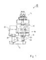
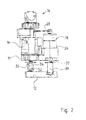
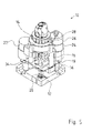
- a rotary laser which is designated by the reference numeral 10 and is arranged in an outer casing, not shown, of the laser.
- a corresponding rotary laser also called a rotary laser, which comprises an at least segmentally rotating laser beam is z. B. used in construction, to define a defined inclined plane, in particular a horizontally extending plane.
- a laser beam is emitted by a laser unit, which is deflected by about 90 ° from a deflection device, which in turn is rotatably mounted in a rotary head.
- the axis of rotation intersects with the laser beam axis of the deflected laser beam.
- the deflection can be such.
- B. act to a pentaprism.
- the laser unit with the rotary head must be adjustable to the desired extent to a base of the rotary laser in order to set the desired plane of rotation of the laser radiation.
- the laser unit and the recording head receiving the rotary head have electronic dragonflies for actuating actuators in a control loop in order to achieve the desired horizontal alignment of the recording with a base element supporting the rotary laser.
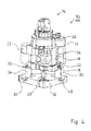
- the inner part of the rotary laser shown in the figures comprises a plate-shaped base element 12, which extends within the housing of the rotary laser, not shown, but also optionally closes the housing on the bottom side.
- the base member 12 is plate-shaped, without thereby limiting the invention.
- the rotary head 14 and arranged in a housing 16 laser unit start from a receptacle 18, which is also referred to as a carrier.
- the carrier 18 is plate-shaped or comprises a plate-shaped carrier element 19 and according to the invention connected to the base member 12 via a solid-body joint 20.
- the output signals are used to control gear motors 22, 24 to regulate, so that the receptacle 18 regardless of the position of the base member 12 aligned to the horizontal and thus of the rotary head 14 deflected laser beam can be deflected in a horizontally extending plane of rotation.
- the existing in the rotary head 14 beam deflecting device such as pentaprism is offset by means of another motor 26 and a belt 28 in rotational movement.
- the rotary head with the housing 16 extending from the receptacle 18 may form a unit, but are preferably components manufactured separately.
- a spindle 30, 32 set in rotary motion, which engages in a formed as a sleeve 34, 36 spindle nut, which in turn is supported on the base member 12 and formed in this wells 38, 40.
- the spindle 30, 32 are adjusted to the sleeve 34, 36, with the result that the receptacle 18 is tiltable to the base member 12 in the desired extent.
- the sleeve 34, 36 is preferably connected to a spring element, not shown, so that a relative movement in the longitudinal direction of the sleeve 34, 36 to the base element 12 is prevented.
- the tilting or tilting of the receptacle 18 to the base member 12 enabling spindles 30, 32 and spindle sleeves 34, 36 are aligned with the solid joint 20 such that between them extending connecting lines, so on the one hand, a connecting line between the longitudinal axis of the spindle 30 and the longitudinal axis of the solid-body joint 20 and, on the other hand, a connecting line between the longitudinal axis of the spindle 32 and the longitudinal axis of the solid-body joint 20, including a right-hand or near-right angle.
- This ensures that upon actuation of a motor 22 to 24, a tilting of the receptacle 18 and thus the laser unit and the rotary head 14 takes place solely in one axis.
- the solid-state joint has a cuboid geometry, with the solid-body joint 20 being composed of a middle part 42 and end sections 44, 46 which merge into the receptacle 18 and the base element 12.
- the cross section of the solid-body joint 20, starting from the middle part 42, increases in the direction of the receptacle 18 or of the base element 12.
- the solid-state joint 20 is symmetrical to a plane (dashed line 56 in FIG Fig. 7 ) which perpendicularly intersects the longitudinal axis of the solid-body joint 20 and extends centrally between facing surfaces of the support plate 19 and the base plate 12. From the surfaces of the solid state joint 20 goes out.
- the solid-state joint 20 is aligned with the spindles 30, 32 such that the lines extending therefrom and intersecting the longitudinal axis of the solid-body joint 20 pass vertically through the outer surfaces 50, 52 of the middle part 42.
- the inventive solid-body joint 20 results in a play-free tilting of the receptacle 18 to the base element 12 without friction occurring. Thus, a lubrication is not required. Furthermore, the solid-body joint is maintenance-free.
- the receptacle 18 with the solid-body joint 20 and the base element 12 are preferably made of polypropylene or other suitable materials such as POM (polyoxymethylene) and are preferably produced by injection molding. Thus, a cost-effective production of the corresponding unit is possible.
- the housing 16 accommodating the laser unit can be a component produced separately from the receptacle 18 or the support plate 19 and can be connected to the receptacle 18 via screwed or latched connections.
Landscapes
- Physics & Mathematics (AREA)
- Engineering & Computer Science (AREA)
- General Physics & Mathematics (AREA)
- Radar, Positioning & Navigation (AREA)
- Remote Sensing (AREA)
- Lasers (AREA)
- Laser Beam Processing (AREA)
- Semiconductor Lasers (AREA)
- Moving Of The Head For Recording And Reproducing By Optical Means (AREA)
- Aiming, Guidance, Guns With A Light Source, Armor, Camouflage, And Targets (AREA)
Applications Claiming Priority (1)
| Application Number | Priority Date | Filing Date | Title |
|---|---|---|---|
| DE202008008821U DE202008008821U1 (de) | 2008-08-28 | 2008-08-28 | Laservorrichtung |
Publications (3)
| Publication Number | Publication Date |
|---|---|
| EP2159539A2 true EP2159539A2 (fr) | 2010-03-03 |
| EP2159539A3 EP2159539A3 (fr) | 2011-08-31 |
| EP2159539B1 EP2159539B1 (fr) | 2013-03-13 |
Family
ID=41396288
Family Applications (1)
| Application Number | Title | Priority Date | Filing Date |
|---|---|---|---|
| EP09168701A Active EP2159539B1 (fr) | 2008-08-28 | 2009-08-26 | Dispositif laser |
Country Status (5)
| Country | Link |
|---|---|
| US (1) | US8171649B2 (fr) |
| EP (1) | EP2159539B1 (fr) |
| JP (1) | JP5372663B2 (fr) |
| CN (1) | CN101662119B (fr) |
| DE (1) | DE202008008821U1 (fr) |
Families Citing this family (6)
| Publication number | Priority date | Publication date | Assignee | Title |
|---|---|---|---|---|
| JP5550855B2 (ja) * | 2009-06-12 | 2014-07-16 | 株式会社トプコン | 回転レーザ出射装置 |
| US9441967B2 (en) | 2013-05-31 | 2016-09-13 | Stanley Black & Decker Inc. | Laser level system |
| DE102014004158A1 (de) | 2014-03-17 | 2015-09-17 | Technische Universität Dresden | Verfahren zur Herstellung von Strukturelementen aus Lasteinleitungselement und Faser-Kunststoff-Verbund-Hohlprofil und Strukturelemente |
| US9664514B2 (en) * | 2015-10-08 | 2017-05-30 | Precaster Enterprises Co., Ltd. | Laser level assembly |
| CN113205694B (zh) * | 2021-04-15 | 2023-10-13 | 山西路泽交通科技有限公司 | 一种道路交通安全智能控制方法及系统 |
| CN222351950U (zh) | 2021-10-11 | 2025-01-14 | 米沃奇电动工具公司 | 用于激光水平仪装置的机动化安装件、机动化装置以及可调整机动化装置 |
Citations (8)
| Publication number | Priority date | Publication date | Assignee | Title |
|---|---|---|---|---|
| EP0854351A2 (fr) | 1997-01-21 | 1998-07-22 | Kabushiki Kaisha Topcon | Instrument d'arpentage à laser |
| US6688011B2 (en) | 2002-06-18 | 2004-02-10 | Agatec | Modular laser system for level determination |
| DE102004024755A1 (de) | 2004-05-12 | 2005-12-08 | Fraunhofer-Gesellschaft zur Förderung der angewandten Forschung e.V. | Halterung für optische Elemente |
| DE102004053249A1 (de) | 2004-11-04 | 2006-05-11 | Hilti Ag | Baulaser mit neigbarem Umlenkmittel |
| DE102004052154A1 (de) | 2004-10-24 | 2006-05-11 | Berliner Elektronenspeicherring-Gesellschaft für Synchrotronstrahlung mbH | Rotationslager zur hochgenauen Winkelpositionierung eines Gegenstandes |
| DE102004011724B4 (de) | 2004-02-06 | 2006-08-10 | Physik Instrumente (Pi) Gmbh & Co. Kg | Miniaturisierte Zweiachsen-Piezo-Betätigungseinrichtung |
| EP1484578B1 (fr) | 2003-06-06 | 2007-01-24 | HILTI Aktiengesellschaft | Laser rotatif pour la construction |
| DE102006004898A1 (de) | 2006-02-03 | 2007-08-09 | Dr. Johannes Heidenhain Gmbh | Abtastsystem einer Positionsmesseinrichtung |
Family Cites Families (14)
| Publication number | Priority date | Publication date | Assignee | Title |
|---|---|---|---|---|
| DE1975746U (de) | 1967-07-28 | 1967-12-28 | Siemens Ag | Dieselelektrisches fahrzeug mit elektrischer getriebeanordnung. |
| JPH0479209U (fr) * | 1990-11-26 | 1992-07-10 | ||
| JP2917261B2 (ja) * | 1992-03-19 | 1999-07-12 | 株式会社トプコン | レーザ測量機 |
| JP3454926B2 (ja) * | 1994-07-29 | 2003-10-06 | 株式会社ソキア | 基準平面設定装置 |
| AU5381096A (en) * | 1995-04-03 | 1996-10-23 | Momentum Laser, Inc. | Laser level |
| JPH0982065A (ja) * | 1995-09-18 | 1997-03-28 | Sony Corp | テープカセット |
| US5991005A (en) * | 1996-04-11 | 1999-11-23 | Nikon Corporation | Stage apparatus and exposure apparatus having the same |
| DE19757461A1 (de) | 1997-12-23 | 1999-06-24 | Hilti Ag | Baulaser |
| JP2000249207A (ja) * | 1999-03-04 | 2000-09-12 | Olympus Optical Co Ltd | 変位拡大機構 |
| US6346710B1 (en) * | 1998-08-31 | 2002-02-12 | Olympus Optical Co., Ltd. | Stage apparatus including displacement amplifying mechanism |
| DE20021784U1 (de) * | 2000-12-22 | 2001-03-01 | Stabila-Messgeräte Gustav Ullrich GmbH & Co KG, 76855 Annweiler | Lasernivellierer mit Schutzgehäuse |
| JP4610117B2 (ja) * | 2001-03-29 | 2011-01-12 | 富士フイルム株式会社 | フーリエ変換縞解析方法および装置 |
| KR100396021B1 (ko) * | 2001-05-25 | 2003-08-27 | 박희재 | 초정밀 이송장치 |
| TWI274854B (en) | 2005-08-31 | 2007-03-01 | Asia Optical Co Inc | Laser level |
-
2008
- 2008-08-28 DE DE202008008821U patent/DE202008008821U1/de not_active Expired - Lifetime
-
2009
- 2009-08-14 US US12/541,212 patent/US8171649B2/en active Active
- 2009-08-26 EP EP09168701A patent/EP2159539B1/fr active Active
- 2009-08-28 JP JP2009198623A patent/JP5372663B2/ja active Active
- 2009-08-28 CN CN2009101720969A patent/CN101662119B/zh active Active
Patent Citations (8)
| Publication number | Priority date | Publication date | Assignee | Title |
|---|---|---|---|---|
| EP0854351A2 (fr) | 1997-01-21 | 1998-07-22 | Kabushiki Kaisha Topcon | Instrument d'arpentage à laser |
| US6688011B2 (en) | 2002-06-18 | 2004-02-10 | Agatec | Modular laser system for level determination |
| EP1484578B1 (fr) | 2003-06-06 | 2007-01-24 | HILTI Aktiengesellschaft | Laser rotatif pour la construction |
| DE102004011724B4 (de) | 2004-02-06 | 2006-08-10 | Physik Instrumente (Pi) Gmbh & Co. Kg | Miniaturisierte Zweiachsen-Piezo-Betätigungseinrichtung |
| DE102004024755A1 (de) | 2004-05-12 | 2005-12-08 | Fraunhofer-Gesellschaft zur Förderung der angewandten Forschung e.V. | Halterung für optische Elemente |
| DE102004052154A1 (de) | 2004-10-24 | 2006-05-11 | Berliner Elektronenspeicherring-Gesellschaft für Synchrotronstrahlung mbH | Rotationslager zur hochgenauen Winkelpositionierung eines Gegenstandes |
| DE102004053249A1 (de) | 2004-11-04 | 2006-05-11 | Hilti Ag | Baulaser mit neigbarem Umlenkmittel |
| DE102006004898A1 (de) | 2006-02-03 | 2007-08-09 | Dr. Johannes Heidenhain Gmbh | Abtastsystem einer Positionsmesseinrichtung |
Also Published As
| Publication number | Publication date |
|---|---|
| US20100050447A1 (en) | 2010-03-04 |
| US8171649B2 (en) | 2012-05-08 |
| JP5372663B2 (ja) | 2013-12-18 |
| JP2010054509A (ja) | 2010-03-11 |
| EP2159539A3 (fr) | 2011-08-31 |
| CN101662119B (zh) | 2012-11-07 |
| DE202008008821U1 (de) | 2010-02-11 |
| EP2159539B1 (fr) | 2013-03-13 |
| CN101662119A (zh) | 2010-03-03 |
Similar Documents
| Publication | Publication Date | Title |
|---|---|---|
| EP2159539B1 (fr) | Dispositif laser | |
| EP1035426A2 (fr) | Dispositif pour déplacer un élément optique le long de l'axe optique | |
| DE3844659A1 (de) | Mikromanipulator | |
| DE3741016A1 (de) | Einstellvorrichtung zum einstellen von optischen elementen mit zwei freiheitsgraden | |
| EP2154474B1 (fr) | Appareil laser | |
| DE202007007193U1 (de) | Selbst-Nivellierende Laservorrichtung | |
| EP2361443B1 (fr) | Convertisseur d'énergie électromécanique destiné à produire de l'énergie électrique à partir de mouvements mécaniques | |
| DE4020299C2 (de) | Spiegelhaltevorrichtung | |
| EP1484578B1 (fr) | Laser rotatif pour la construction | |
| DE3615930A1 (de) | Vorrichtung zum einstellen der lage eines spiegels | |
| EP3236205A1 (fr) | Laser rotatif | |
| DE19909913B4 (de) | Elektromechanische Antriebsvorrichtung | |
| EP0469412B1 (fr) | Pivot de flexion pour la liaison articulée de deux pièces | |
| DE19742205A1 (de) | Mikropositioniereinrichtung | |
| EP0831351A2 (fr) | Dispositif de basculement | |
| DE60219018T2 (de) | Gelenkverbindung | |
| EP3633679A1 (fr) | Support mécanique réglable pour un ajustement fin de la position d'un élément tel qu'une lentille | |
| EP1959231A2 (fr) | Niveau, instrument de prise d'aplomb et de calibrage d'angle avec un fil à plomb à suspension pendulaire | |
| WO2008011970A2 (fr) | Porte-pièce de position variable destiné à une machine et installation d'usinage comprenant un porte-pièce correspondant | |
| DE102020134653B3 (de) | Justierbarer Optikhalter für ein optisches Element | |
| EP1353110B1 (fr) | Table de positionnement | |
| DE19813637C2 (de) | Schraubengetriebe | |
| DE102010041689A1 (de) | Buchse zur Aufnahme eines Steckers mit einem Lichtleiter | |
| DE4419524C2 (de) | Stehachsensystem für geodätische Geräte | |
| DE10155637B4 (de) | Halte-und Fixiereinrichtung für optische Elemente |
Legal Events
| Date | Code | Title | Description |
|---|---|---|---|
| PUAI | Public reference made under article 153(3) epc to a published international application that has entered the european phase |
Free format text: ORIGINAL CODE: 0009012 |
|
| AK | Designated contracting states |
Kind code of ref document: A2 Designated state(s): AT BE BG CH CY CZ DE DK EE ES FI FR GB GR HR HU IE IS IT LI LT LU LV MC MK MT NL NO PL PT RO SE SI SK SM TR |
|
| PUAL | Search report despatched |
Free format text: ORIGINAL CODE: 0009013 |
|
| AK | Designated contracting states |
Kind code of ref document: A3 Designated state(s): AT BE BG CH CY CZ DE DK EE ES FI FR GB GR HR HU IE IS IT LI LT LU LV MC MK MT NL NO PL PT RO SE SI SK SM TR |
|
| RIC1 | Information provided on ipc code assigned before grant |
Ipc: G01C 15/00 20060101AFI20110727BHEP |
|
| 17P | Request for examination filed |
Effective date: 20111224 |
|
| GRAP | Despatch of communication of intention to grant a patent |
Free format text: ORIGINAL CODE: EPIDOSNIGR1 |
|
| GRAS | Grant fee paid |
Free format text: ORIGINAL CODE: EPIDOSNIGR3 |
|
| GRAP | Despatch of communication of intention to grant a patent |
Free format text: ORIGINAL CODE: EPIDOSNIGR1 |
|
| GRAA | (expected) grant |
Free format text: ORIGINAL CODE: 0009210 |
|
| AK | Designated contracting states |
Kind code of ref document: B1 Designated state(s): AT BE BG CH CY CZ DE DK EE ES FI FR GB GR HR HU IE IS IT LI LT LU LV MC MK MT NL NO PL PT RO SE SI SK SM TR |
|
| REG | Reference to a national code |
Ref country code: GB Ref legal event code: FG4D Free format text: NOT ENGLISH |
|
| REG | Reference to a national code |
Ref country code: CH Ref legal event code: EP Ref country code: AT Ref legal event code: REF Ref document number: 601064 Country of ref document: AT Kind code of ref document: T Effective date: 20130315 |
|
| REG | Reference to a national code |
Ref country code: IE Ref legal event code: FG4D Free format text: LANGUAGE OF EP DOCUMENT: GERMAN |
|
| REG | Reference to a national code |
Ref country code: CH Ref legal event code: NV Representative=s name: LUCHS AND PARTNER AG PATENTANWAELTE, CH |
|
| REG | Reference to a national code |
Ref country code: DE Ref legal event code: R096 Ref document number: 502009006464 Country of ref document: DE Effective date: 20130508 |
|
| PG25 | Lapsed in a contracting state [announced via postgrant information from national office to epo] |
Ref country code: NO Free format text: LAPSE BECAUSE OF FAILURE TO SUBMIT A TRANSLATION OF THE DESCRIPTION OR TO PAY THE FEE WITHIN THE PRESCRIBED TIME-LIMIT Effective date: 20130613 Ref country code: SE Free format text: LAPSE BECAUSE OF FAILURE TO SUBMIT A TRANSLATION OF THE DESCRIPTION OR TO PAY THE FEE WITHIN THE PRESCRIBED TIME-LIMIT Effective date: 20130313 Ref country code: BG Free format text: LAPSE BECAUSE OF FAILURE TO SUBMIT A TRANSLATION OF THE DESCRIPTION OR TO PAY THE FEE WITHIN THE PRESCRIBED TIME-LIMIT Effective date: 20130613 Ref country code: LT Free format text: LAPSE BECAUSE OF FAILURE TO SUBMIT A TRANSLATION OF THE DESCRIPTION OR TO PAY THE FEE WITHIN THE PRESCRIBED TIME-LIMIT Effective date: 20130313 Ref country code: ES Free format text: LAPSE BECAUSE OF FAILURE TO SUBMIT A TRANSLATION OF THE DESCRIPTION OR TO PAY THE FEE WITHIN THE PRESCRIBED TIME-LIMIT Effective date: 20130624 |
|
| REG | Reference to a national code |
Ref country code: NL Ref legal event code: VDEP Effective date: 20130313 |
|
| REG | Reference to a national code |
Ref country code: LT Ref legal event code: MG4D |
|
| PG25 | Lapsed in a contracting state [announced via postgrant information from national office to epo] |
Ref country code: SI Free format text: LAPSE BECAUSE OF FAILURE TO SUBMIT A TRANSLATION OF THE DESCRIPTION OR TO PAY THE FEE WITHIN THE PRESCRIBED TIME-LIMIT Effective date: 20130313 Ref country code: GR Free format text: LAPSE BECAUSE OF FAILURE TO SUBMIT A TRANSLATION OF THE DESCRIPTION OR TO PAY THE FEE WITHIN THE PRESCRIBED TIME-LIMIT Effective date: 20130614 Ref country code: FI Free format text: LAPSE BECAUSE OF FAILURE TO SUBMIT A TRANSLATION OF THE DESCRIPTION OR TO PAY THE FEE WITHIN THE PRESCRIBED TIME-LIMIT Effective date: 20130313 Ref country code: LV Free format text: LAPSE BECAUSE OF FAILURE TO SUBMIT A TRANSLATION OF THE DESCRIPTION OR TO PAY THE FEE WITHIN THE PRESCRIBED TIME-LIMIT Effective date: 20130313 |
|
| PG25 | Lapsed in a contracting state [announced via postgrant information from national office to epo] |
Ref country code: HR Free format text: LAPSE BECAUSE OF FAILURE TO SUBMIT A TRANSLATION OF THE DESCRIPTION OR TO PAY THE FEE WITHIN THE PRESCRIBED TIME-LIMIT Effective date: 20130313 |
|
| PG25 | Lapsed in a contracting state [announced via postgrant information from national office to epo] |
Ref country code: EE Free format text: LAPSE BECAUSE OF FAILURE TO SUBMIT A TRANSLATION OF THE DESCRIPTION OR TO PAY THE FEE WITHIN THE PRESCRIBED TIME-LIMIT Effective date: 20130313 Ref country code: PT Free format text: LAPSE BECAUSE OF FAILURE TO SUBMIT A TRANSLATION OF THE DESCRIPTION OR TO PAY THE FEE WITHIN THE PRESCRIBED TIME-LIMIT Effective date: 20130715 Ref country code: RO Free format text: LAPSE BECAUSE OF FAILURE TO SUBMIT A TRANSLATION OF THE DESCRIPTION OR TO PAY THE FEE WITHIN THE PRESCRIBED TIME-LIMIT Effective date: 20130313 Ref country code: CZ Free format text: LAPSE BECAUSE OF FAILURE TO SUBMIT A TRANSLATION OF THE DESCRIPTION OR TO PAY THE FEE WITHIN THE PRESCRIBED TIME-LIMIT Effective date: 20130313 Ref country code: IS Free format text: LAPSE BECAUSE OF FAILURE TO SUBMIT A TRANSLATION OF THE DESCRIPTION OR TO PAY THE FEE WITHIN THE PRESCRIBED TIME-LIMIT Effective date: 20130713 Ref country code: SK Free format text: LAPSE BECAUSE OF FAILURE TO SUBMIT A TRANSLATION OF THE DESCRIPTION OR TO PAY THE FEE WITHIN THE PRESCRIBED TIME-LIMIT Effective date: 20130313 Ref country code: NL Free format text: LAPSE BECAUSE OF FAILURE TO SUBMIT A TRANSLATION OF THE DESCRIPTION OR TO PAY THE FEE WITHIN THE PRESCRIBED TIME-LIMIT Effective date: 20130313 |
|
| PG25 | Lapsed in a contracting state [announced via postgrant information from national office to epo] |
Ref country code: CY Free format text: LAPSE BECAUSE OF FAILURE TO SUBMIT A TRANSLATION OF THE DESCRIPTION OR TO PAY THE FEE WITHIN THE PRESCRIBED TIME-LIMIT Effective date: 20130313 Ref country code: PL Free format text: LAPSE BECAUSE OF FAILURE TO SUBMIT A TRANSLATION OF THE DESCRIPTION OR TO PAY THE FEE WITHIN THE PRESCRIBED TIME-LIMIT Effective date: 20130313 |
|
| PLBE | No opposition filed within time limit |
Free format text: ORIGINAL CODE: 0009261 |
|
| STAA | Information on the status of an ep patent application or granted ep patent |
Free format text: STATUS: NO OPPOSITION FILED WITHIN TIME LIMIT |
|
| PG25 | Lapsed in a contracting state [announced via postgrant information from national office to epo] |
Ref country code: DK Free format text: LAPSE BECAUSE OF FAILURE TO SUBMIT A TRANSLATION OF THE DESCRIPTION OR TO PAY THE FEE WITHIN THE PRESCRIBED TIME-LIMIT Effective date: 20130313 |
|
| 26N | No opposition filed |
Effective date: 20131216 |
|
| BERE | Be: lapsed |
Owner name: STABILA MESSGERATE GUSTAV ULLRICH G.M.B.H. Effective date: 20130831 |
|
| REG | Reference to a national code |
Ref country code: DE Ref legal event code: R097 Ref document number: 502009006464 Country of ref document: DE Effective date: 20131216 |
|
| PG25 | Lapsed in a contracting state [announced via postgrant information from national office to epo] |
Ref country code: MC Free format text: LAPSE BECAUSE OF FAILURE TO SUBMIT A TRANSLATION OF THE DESCRIPTION OR TO PAY THE FEE WITHIN THE PRESCRIBED TIME-LIMIT Effective date: 20130313 |
|
| REG | Reference to a national code |
Ref country code: IE Ref legal event code: MM4A |
|
| PG25 | Lapsed in a contracting state [announced via postgrant information from national office to epo] |
Ref country code: BE Free format text: LAPSE BECAUSE OF NON-PAYMENT OF DUE FEES Effective date: 20130831 |
|
| PG25 | Lapsed in a contracting state [announced via postgrant information from national office to epo] |
Ref country code: IE Free format text: LAPSE BECAUSE OF NON-PAYMENT OF DUE FEES Effective date: 20130826 |
|
| PG25 | Lapsed in a contracting state [announced via postgrant information from national office to epo] |
Ref country code: SM Free format text: LAPSE BECAUSE OF FAILURE TO SUBMIT A TRANSLATION OF THE DESCRIPTION OR TO PAY THE FEE WITHIN THE PRESCRIBED TIME-LIMIT Effective date: 20130313 |
|
| PG25 | Lapsed in a contracting state [announced via postgrant information from national office to epo] |
Ref country code: TR Free format text: LAPSE BECAUSE OF FAILURE TO SUBMIT A TRANSLATION OF THE DESCRIPTION OR TO PAY THE FEE WITHIN THE PRESCRIBED TIME-LIMIT Effective date: 20130313 Ref country code: MT Free format text: LAPSE BECAUSE OF FAILURE TO SUBMIT A TRANSLATION OF THE DESCRIPTION OR TO PAY THE FEE WITHIN THE PRESCRIBED TIME-LIMIT Effective date: 20130313 |
|
| PG25 | Lapsed in a contracting state [announced via postgrant information from national office to epo] |
Ref country code: MK Free format text: LAPSE BECAUSE OF FAILURE TO SUBMIT A TRANSLATION OF THE DESCRIPTION OR TO PAY THE FEE WITHIN THE PRESCRIBED TIME-LIMIT Effective date: 20130313 Ref country code: LU Free format text: LAPSE BECAUSE OF NON-PAYMENT OF DUE FEES Effective date: 20130826 Ref country code: HU Free format text: LAPSE BECAUSE OF FAILURE TO SUBMIT A TRANSLATION OF THE DESCRIPTION OR TO PAY THE FEE WITHIN THE PRESCRIBED TIME-LIMIT; INVALID AB INITIO Effective date: 20090826 |
|
| REG | Reference to a national code |
Ref country code: FR Ref legal event code: PLFP Year of fee payment: 8 |
|
| REG | Reference to a national code |
Ref country code: FR Ref legal event code: PLFP Year of fee payment: 9 |
|
| REG | Reference to a national code |
Ref country code: FR Ref legal event code: PLFP Year of fee payment: 10 |
|
| PGFP | Annual fee paid to national office [announced via postgrant information from national office to epo] |
Ref country code: CH Payment date: 20200819 Year of fee payment: 12 |
|
| REG | Reference to a national code |
Ref country code: CH Ref legal event code: PL |
|
| PG25 | Lapsed in a contracting state [announced via postgrant information from national office to epo] |
Ref country code: LI Free format text: LAPSE BECAUSE OF NON-PAYMENT OF DUE FEES Effective date: 20210831 Ref country code: CH Free format text: LAPSE BECAUSE OF NON-PAYMENT OF DUE FEES Effective date: 20210831 |
|
| P01 | Opt-out of the competence of the unified patent court (upc) registered |
Effective date: 20230528 |
|
| PGFP | Annual fee paid to national office [announced via postgrant information from national office to epo] |
Ref country code: DE Payment date: 20250825 Year of fee payment: 17 |
|
| PGFP | Annual fee paid to national office [announced via postgrant information from national office to epo] |
Ref country code: IT Payment date: 20250825 Year of fee payment: 17 |
|
| PGFP | Annual fee paid to national office [announced via postgrant information from national office to epo] |
Ref country code: GB Payment date: 20250708 Year of fee payment: 17 |
|
| PGFP | Annual fee paid to national office [announced via postgrant information from national office to epo] |
Ref country code: FR Payment date: 20250829 Year of fee payment: 17 Ref country code: AT Payment date: 20250821 Year of fee payment: 17 |