EP2178782B1 - Steuerung zur begrenzung des trommelfelldrucks von aufzugspassagieren und verfahren dafür - Google Patents
Steuerung zur begrenzung des trommelfelldrucks von aufzugspassagieren und verfahren dafür Download PDFInfo
- Publication number
- EP2178782B1 EP2178782B1 EP08797257A EP08797257A EP2178782B1 EP 2178782 B1 EP2178782 B1 EP 2178782B1 EP 08797257 A EP08797257 A EP 08797257A EP 08797257 A EP08797257 A EP 08797257A EP 2178782 B1 EP2178782 B1 EP 2178782B1
- Authority
- EP
- European Patent Office
- Prior art keywords
- elevator
- passenger
- pressure differential
- differential value
- elevator car
- Prior art date
- Legal status (The legal status is an assumption and is not a legal conclusion. Google has not performed a legal analysis and makes no representation as to the accuracy of the status listed.)
- Not-in-force
Links
- 238000000034 method Methods 0.000 title claims description 35
- 230000036461 convulsion Effects 0.000 claims description 27
- 230000001133 acceleration Effects 0.000 claims description 25
- 210000000959 ear middle Anatomy 0.000 claims description 22
- 210000000883 ear external Anatomy 0.000 claims description 17
- 210000005069 ears Anatomy 0.000 abstract description 3
- 238000004088 simulation Methods 0.000 abstract description 3
- 238000012544 monitoring process Methods 0.000 abstract 1
- 230000008859 change Effects 0.000 description 24
- 210000003454 tympanic membrane Anatomy 0.000 description 11
- 230000007423 decrease Effects 0.000 description 10
- 230000006378 damage Effects 0.000 description 7
- 238000010586 diagram Methods 0.000 description 6
- 210000002388 eustachian tube Anatomy 0.000 description 6
- 210000003027 ear inner Anatomy 0.000 description 4
- 208000027418 Wounds and injury Diseases 0.000 description 3
- 238000013459 approach Methods 0.000 description 3
- 238000004364 calculation method Methods 0.000 description 3
- 230000003111 delayed effect Effects 0.000 description 3
- 208000014674 injury Diseases 0.000 description 3
- 230000002045 lasting effect Effects 0.000 description 3
- 208000032843 Hemorrhage Diseases 0.000 description 2
- 230000000694 effects Effects 0.000 description 2
- 238000012986 modification Methods 0.000 description 2
- 230000004048 modification Effects 0.000 description 2
- 230000006978 adaptation Effects 0.000 description 1
- 238000013473 artificial intelligence Methods 0.000 description 1
- 230000009286 beneficial effect Effects 0.000 description 1
- 230000015556 catabolic process Effects 0.000 description 1
- 238000006243 chemical reaction Methods 0.000 description 1
- 230000009194 climbing Effects 0.000 description 1
- 238000006731 degradation reaction Methods 0.000 description 1
- 230000001934 delay Effects 0.000 description 1
- 238000009434 installation Methods 0.000 description 1
- 230000002452 interceptive effect Effects 0.000 description 1
- 230000007246 mechanism Effects 0.000 description 1
- 230000000737 periodic effect Effects 0.000 description 1
- 230000004044 response Effects 0.000 description 1
Images




Classifications
-
- B—PERFORMING OPERATIONS; TRANSPORTING
- B66—HOISTING; LIFTING; HAULING
- B66B—ELEVATORS; ESCALATORS OR MOVING WALKWAYS
- B66B1/00—Control systems of elevators in general
- B66B1/24—Control systems with regulation, i.e. with retroactive action, for influencing travelling speed, acceleration, or deceleration
- B66B1/28—Control systems with regulation, i.e. with retroactive action, for influencing travelling speed, acceleration, or deceleration electrical
- B66B1/30—Control systems with regulation, i.e. with retroactive action, for influencing travelling speed, acceleration, or deceleration electrical effective on driving gear, e.g. acting on power electronics, on inverter or rectifier controlled motor
-
- B—PERFORMING OPERATIONS; TRANSPORTING
- B66—HOISTING; LIFTING; HAULING
- B66B—ELEVATORS; ESCALATORS OR MOVING WALKWAYS
- B66B1/00—Control systems of elevators in general
- B66B1/24—Control systems with regulation, i.e. with retroactive action, for influencing travelling speed, acceleration, or deceleration
- B66B1/28—Control systems with regulation, i.e. with retroactive action, for influencing travelling speed, acceleration, or deceleration electrical
Definitions
- the present application relates to elevators and elevator control systems.
- the present application provides a system and method for controlling an elevator car while limiting the passenger discomfort caused by pressure changes.
- Atmospheric air pressure can be described as the pressure at any given point in the earth's atmosphere. Atmospheric air pressure increases as an elevator travels downward, and decreases as an elevator travels upward. If these pressure changes occur too rapidly, they may cause passenger discomfort, specifically to a passenger's ears.
- the ear can be divided into three sections: (1) the outer ear, (2) the middle ear, and (3) the inner ear.
- the middle ear is an air-filled chamber that is connected to the nose and throat through a channel called the eustachian tube.
- the middle ear is surrounded at respective sides by the outer ear and the inner ear. Air moves through the eustachian tube into the middle ear to equalize the pressure with the pressure of the outer ear.
- the middle ear contains the tympanic member, otherwise known as the ear drum. Hence, the pressure in the middle ear is often referred to as the typmanic pressure.
- the air pressure of the outer ear decreases with the atmospheric pressure.
- the pressure in the middle ear generally does not adjust as quickly to pressure changes.
- the automatic adjustment for pressure differences in the normal human ear will be referred to as "natural relief.”
- the outer ear therefore has lower air pressure compared to the middle ear due to the middle ear's slower adjustment to pressure changes.
- the air pressure in the middle air remains higher until equalized.
- the tympanic membrane of the ear otherwise known as the eardrum, may bulge towards the outer ear in reaction to having a higher pressure in the middle ear. If this bulge becomes too great, the person may experience discomfort, or injury to the eardrum including small hemorrhages in the ear drum, small blisters, or other injuries. In extreme cases, the eardrum may rupture, which may lead to permanent damage.
- the atmospheric pressure increases in the outer ear.
- This pressure increase in the outer ear results in the pressure in the middle ear being lower compared to the outer ear.
- This pressure difference between the outer ear and the middle ear can cause the tympanic membrane of the ear to bulge inward toward the middle ear. If this bulge becomes too great, the person may experience discomfort, small hemorrhages in the ear drum, small blisters, or other injuries. In extreme cases, the eardrum may rupture, which may lead to permanent damage.
- the person has a cold or other condition that causes partial or complete blockage of the Eustachian tube, natural relief may not be able to equalize the increased pressure difference, such that discomfort may persist for an extended period of time.
- the sudden opening of the Eustachian tube may force a rapid pressure change in the middle ear. This sudden pressure change in the middle ear can be further transmitted to the inner ear and possibly damage the delicate mechanisms of the middle ear (i.e. the ear drum) and the inner ear.
- FIG. 1 depicts a schematic diagram of an exemplary elevator system.
- FIG. 2 depicts a block diagram for an exemplary system for controlling an elevator.
- FIG. 3 depicts a block diagram for an alternative exemplary system for controlling an elevator.
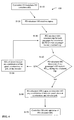
- FIG. 4 depicts an exemplary flow chart for a pressure differential calculator.
- FIG. 5 depicts an exemplary flow chart for simulating a passenger's trip.
- FIG. 6 depicts an exemplary flow chart for a pressure differential database and database updater.
- FIG. 7 shows a table depicting exemplary pressure information.
- FIG. 8 shows a chart depicting an exemplary air pressure differential experienced by a passenger descending in an elevator car.
- FIG. 1 depicts an exemplary elevator system (40) including multiple elevator cars (42) positioned within a plurality of elevator shafts (44). Elevator cars (42) travel vertically within respective shafts (44) and stop at a plurality of landings (46). As depicted in the example, each of the various landings (46) includes an external destination entry device (48). Elevator cars (42) include internal destination entry devices (49). Examples of destination entry devices include interactive displays, computer touch screens, or any combination thereof. Still, other structures, components, and techniques for destination entry devices are well known and may be used. Yet further, traditional up/down call signals may be used at a landing.
- a controller (50) communicates with elevator system (40). As will be explained in more detail hereafter, controller (50) governs the movement of elevator cars (42) to limit the air pressure differential ("PD") experienced by passenger. The movement of elevators (42), as directed by controller (50), ensures that passengers' PDs do not exceed a maximum allowable PD ("PD max ").
- PD max a maximum allowable PD
- a passenger's PD may be defined as the pressure difference between a passenger's outer ear and middle ear.
- controller (50) operates to limit passengers' PDs by adjusting the speed, direction, and jerk of elevators cars.
- the term elevator jerk describes the rate of change in relation to an elevator's acceleration.
- Controller (50) receives suitable inputs from elevator system (40) in order to appropriately adjust the speed, direction, and jerk of elevator cars. Examples of such inputs include new destination calls, the status of each elevator, pressure readings throughout the elevator shafts, and the current time.
- Elevator system (40) may use any suitable structure, component, and technique to obtain and send these or other inputs to controller (50).
- elevator system (40) may use sensors (52) to gauge the air pressure in the elevator shaft.
- controller (50) may use any suitable structure, component, and technique to receive such inputs.
- Controller (50) communicates at least some of the inputs described above to a PD calculator (60) (see FIG. 2 and FIG. 3 ).
- PD calculator (60) uses the inputs to determine the correct settings at which to operate the elevator cars. These settings may include any combination of elevator speed, direction, and jerk, selected such that no passenger's PD exceeds PD max .
- PD calculator (60) sends the settings as outputs to controller (50). Controller (50) uses the received outputs to control the speed, direction, and jerk of the elevator cars.
- An exemplary operation of PD calculator (60) is shown in the flowchart of FIG. 4 and described below.
- Passenger information may include information specific to each individual passenger, or a group of passengers. Examples of passenger information includes call signals, destination choices, current and past pressure differentials for a passenger, elevator weight, the time when a passenger enters and exits the elevator, and so on.
- the passenger information in PD database (70) may need to be updated because passengers' PDs may change over time due to natural relief. Also, passenger information may need to be updated when a new passenger enters the elevator or a previous passenger exits the elevator.
- controller (50) communicates inputs to PD calculator (60).
- PD calculator (60) also obtains inputs from database (70).
- PD calculator (60) uses these inputs to monitor passengers' PDs as described below and send outputs to controller (50).
- Controller (50) uses the outputs from PD calculator (60) to control one or more elevators so that no passenger's PD exceeds PD max .
- Controller (50) communicates with database updater (80) which refreshes database (70) to contain current passenger information.
- PD calculator (60) receives inputs only from controller (50). Controller (50) also communicates with database (70) via database updater (80). Controller (50) sends the passenger information received from database updater (80) to PD calculator (60). PD calculator (60) uses information from controller (50) and database (70) to formulate outputs. These outputs are sent to controller (50). Controller (50) uses the outputs to control the movement of elevators so that no passenger's PD exceeds PD max .
- controller (50) initializes PD calculator (60) in step (S 110).
- the initialization of controller (50) may occur at various times, for example, upon receiving a new destination call signal or after the elevator doors close.
- the systems discussed herein may be incorporated into previously known methods and apparatuses for assigning or controlling elevator cars, such as that disclosed in U.S. Patent No. 6,439,349 , entitled “Method and Apparatus for Assigning New Hall Calls To One of a Plurality of Elevator Cars," issued August 27, 2002, the disclosure of which is incorporated herein by reference.
- controller (50) sends at least one input to PD calculator (60) in step (S120).
- these inputs may include, but are not limited to: the maximum and the minimum speed of the elevator, the maximum and minimum jerk of the elevator, a trip distance, passenger information including destination calls and current PD, the maximum allowable PD, the distance the elevator is to travel between the departure floor and the arrival floor, and pressure information.
- Pressure information may be the atmospheric pressure at various locations in the elevator shaft, the air pressure at specific floors, the air pressure differences between floors, or any combination thereof.
- Controller (50) may use any suitable method and device for obtaining and sending these inputs to PD calculator (60).
- controller (50) may be a general purpose computer pre-programmed with the maximum and minimum speed of the elevator, the maximum and minimum jerk of the elevator, pressure information, and PD max . It will be understood that controller (50) may obtain passenger information from PD database (70). Likewise, controller (50) may obtain pressure information through sensors (52) positioned in elevator shaft (44).
- PD calculator (60) simulates a complete single trip for each passenger in step (S 130).
- a trip is defined as the elevator traveling from a first position to a second position. For example, two trips would occur where an elevator car picks up a passenger on the 150 th floor, stops at the 100 th floor for another passenger, and proceeds to the 1 st floor where both passengers depart.
- the first passenger trip is traveling from the 150 th floor to the 100 th floor.
- the second passenger trip is traveling from the 100 th floor to the 1 st floor.
- a trip may be defined as the steps necessary to carry passengers to requested destinations and address any elevator calls from waiting passengers.
- a passenger trip would occur when the elevator car travels from the 150 th floor to the 1 st floor, including picking up a passenger at the 100 th floor.
- Simulating a trip for each passenger is desirable because passengers may have different PD values. For example, a person entering the elevator car at the 150 th floor may have a different PD value compared to a person entering the elevator car at the 100 th floor.
- the flowchart shown in FIG. 5 depicts an exemplary operation for simulating a passenger trip, including determining the pressure change when the elevator car travels between a departure floor and an arrival floor.
- the pressure values at particular floors, or the pressure differentials between floors may be programmed into controller (50), which in turn sends these pressure values to PD calculator (60).
- the pressure information may also be programmed into PD calculator (60) directly.
- Controller (50) and PD calculator (60) may also be provided with the ability to calculate the required pressure information.
- One method for calculating this pressure change between a departure floor and an arrival floor includes determining the pressure changes between (1) the 1 st floor and the departure floor, and (2) the 1 st floor and the arrival floor.
- Equation (1) is described in the publication " Effective Atmospheric Pressure Control for Ultra-High Speed Elevator" in Proceedings of ELEVCON 2004, pp.225-233 by Shudo, T., Y. Fujita, S. Nakagaki, M. Okamoto and A. Yamamoto .
- PC d/l represents the pressure change between the departure floor and the 1 st floor
- PC a/l represents the pressure change between the arrival floor and the 1 st floor
- the passenger's current pressure differential value, PD c is then added to PC d/a to determine the passenger's potential pressure differential, PDp.
- the value of PD p represents the potential pressure differential which would be experienced by a passenger during the trip if no natural relief were to occur during the trip. Where no natural relief occurs, it is presumed that a passenger's PD increases or decreases directly with the pressure changes experienced by the passenger.
- the passenger's current pressure differential, PD c will measure zero when the passenger enters the elevator.
- the passenger's PD c will change when the passenger experiences pressure changes. In some circumstances, for example where a passenger travels slowly, the passenger's PD c may still be zero even though the passenger experienced pressure changes. This will occur where the pressure differential caused by the pressure changes is offset by natural relief.
- the passenger information stored in PD database (70) includes a PD c value for each passenger.
- PD calculator (60) receives this information as an input for the trip simulation calculation.
- PD max is subtracted from PD p to obtain the excess pressure differential value, PD e , as shown in equation (3) below.
- P ⁇ D e P ⁇ D p - P ⁇ D max
- One of the important aspects of the present method is using the passenger's natural relief to reduce the pressure differential experienced by the passenger, whether the elevator car is moving or stopped.
- sky lobbies are provided where natural relief can relieve pressure differences as the passenger walks from one bank of elevators to another.
- the present method uses the passenger's natural relief which occurs while the elevator car is stopped to pick up or discharge passengers to reduce the pressure difference experienced by the passengers' ears as a factor to optimally control the operation of the elevator, and thereby minimize the total passenger travel time.
- the speed of the elevator between destinations can be increased since the passengers will be starting from a lower initial pressure difference, and can therefore experience a higher pressure change per unit time, provided a comfortable ear pressure differential is not exceeded..
- the elevator will need to travel at a speed, acceleration, or jerk to provide the time necessary for natural relief to equalize or at least reduce the passenger's PD e .
- the present method contemplates that elevator run at an acceleration, speed, and/or jerk such that a passenger's PD approaches but does not exceed PD max . This requires equalizing PD e .
- Equalizing PD e can be accomplished by calculating a comfort time, T c .
- the comfort time, T c represents a period of time over which PD e is equalized. More specifically, this comfort time represents the time necessary to equalize PD e based on a rate of natural relief, N r .
- the natural relief rate can be estimated based on pressure change values used by pressurized airline cabins to insure passenger comfort. As is generally understood, while climbing or descending, the automatic pressurization system the rate of altitude change within the airplane cabin is limited to a comfortable range, often around 350 to 450 feet per minute. Using equation (1) above, the lower end of this range, 350 feet per minute (1.75 m/sec.), equates to a pressure change of about 22 pascels/sec.
- T c P ⁇ D e N r
- PD calculator (60) determines in step (S 140) whether any passenger's PD exceeds PD max during the trip. This is determined by examining whether the estimated duration of the simulated trip is less than any passenger's T c . That is, a passenger's PD will exceed PD max during the trip if the simulated trip duration is less than T c . A passenger's PD will not exceed PD max during the trip if the simulated trip duration is greater than T c . Alternatively, PD calculator (60) may only compare the simulated trip duration with the largest T c value where the elevator contains multiple passengers.
- PD calculator (60) performs step (S 150) and alters at least one variable input of the simulated trip so as to increase the trip duration so it is equal to or greater than T c .
- the elevator's speed, acceleration and/or jerk may be reduced. Any suitable methods and techniques may be used to vary the inputs needed to increase the simulated trip duration to a value equal to or greater than T c .
- PD calculator (60) After altering at least one variable input in step (S150), PD calculator (60) either partially or completely repeats step (S 130).
- PD calculator (60) may be configured to only re-calculate the simulated trip duration.
- PD calculator (60) may be configured to only repeat step (S 130) for the passenger whose PD exceeded PD max.
- step (S 140) After iteratively repeating step (S 130), PD calculator (60) repeats step (S 140) to determine whether any passenger's PD exceeds PD max by comparing the simulated trip duration with each passenger's T c . If the simulated trip duration is less than any passenger's T c , steps (S150) and (S140) are repeated. PD calculator (60) continues to repeat steps (S 150) and (S 140) until a determination is made that the simulated trip duration is equal to or greater than every passenger's T c . Upon making a determination that no passenger's PD exceeds PD max , PD calculator (60) outputs the speed, acceleration and jerk values to controller (50) in step (S 150).
- PD calculator (60) may be configured with the ability to calculate elevator speed, acceleration, and jerk based on the target travel time, T c , and distance to be traveled. Using this approach may prevent PD calculator (60) from simulating trips until an adequate value for the car's speed, acceleration, and jerk are found. For example, a passenger enters the elevator at the 120 th floor and selects the lobby as a destination. The distance between the 120 1h floor and the 1 st floor is 486 meters. PD calculator (60) calculates a T c for the passenger of 88.8 seconds.
- PD calculator 60 then would use available elevator speeds, accelerations, and/or jerk capabilities to create a trip for this passenger lasting 88.8 seconds. It will be observed that this methodology permits the system to reduce or optimize the total travel time by taking into account the natural relief of the passenger, while insuring passenger comfort. The average velocity necessary for traveling 486 meters in 88.8 seconds is 5.47 m/s. Numerous devices, systems, and techniques such as artificial intelligence are well known and may be used to create a trip for a passenger lasting a time equal to or greater than T c .
- Controller (50) may also use the output from PD calculator (60) to take into account the delays associated with picking up waiting passengers.
- This embodiment would be especially useful for elevator systems having multiple elevator cars.
- this embodiment (as well as others described herein) may be implemented using the system described in U.S. Patent No. 6,439,349 , titled “Method and Apparatus for Assigning New Hall Calls To One of a Plurality of Elevator Cars," issued August 27, 2002.
- controller (50) analyzes the degree to which that car's speed, acceleration or jerk may be limited as a result of the current PDs of that car's passengers.
- Controller (50) then utilizes that information to assess which car should be assigned to particular waiting passengers, based on their destinations. For example, controller (50) may allocate certain waiting passengers to a car already delayed because of the PD levels associated with one or more of that car's passengers. This improves the efficiency of the operation of the overall elevator system compared to allocating waiting passengers to other cars where travel is not limited by the passengers' PDs.
- controller (50) may be programmed to recognize when multiple cars may potentially arrive at a call signal at about the same time.
- each elevator may be assigned a PD level representative of the passenger for that car having the highest PD or T c .
- controller (50) may calculate an estimated time to inferred destination (ETID) as described in U.S. Patent 6,439,349 . This ETID represents the estimated time for a particular elevator car to reach its final destination. Controller (50) may use the stoppage time associated with allowing passengers to enter and depart the elevator car in calculating the ETID.
- ETID estimated time to inferred destination
- Controller (50) may then use the ETID so calculated to determine which elevator car should address a particular call signal. For example, an elevator car stopping for a waiting call signal would unnecessarily delay passengers which are not PD limited, since that car could travel at maximum speed and/or acceleration. Alternatively, PD limited passengers in a second elevator responding to the same call signal would be unnecessarily delayed already as the need for the car to travel or accelerate more slowly due to at least one passenger's PD. Accordingly, in this example, it would be more efficient for controller (50) to direct the second car to respond to the call signal as its passengers are already delayed due to at least one passenger's PD. Further, allowing the second car to address the call signal will permit natural relief to equalize the passengers PDs such that the second car may travel more quickly to its next destination.
- CC call cost value
- SDF equals the system degradation factor
- ETD stands for estimated time to destination, wherein each car has the a quantity of (n) existing car and hall calls (k).
- the value of CC is calculated respectively for each elevator car in an elevator system.
- the elevator car with the lowest CC is assigned to respond to an elevator car.
- the value for SDF equals the time required for a car to respond to a call signal. Various time periods may be predicted for this amount. For example, the elevator may allocate an increased amount of time to respond to a call signal during peak hours of elevator use due to the increased time required for larger numbers of individuals to enter the elevator. As evidence from equation (5), a higher value for SDF reduces the chance that an elevator is assigned to respond to an elevator car.
- an elevator car may be allotted an SDF of zero, or some other value factoring in a passenger's PD. Stopping to respond to a call signal allows passengers in an elevator car to equalize at least a portion of their respective PD. This equalization caused by natural relief may allow the elevator car to travel faster during its remaining travels compared to when its travels where limited by at least one passenger's PD. In some circumstances, the elevator car may even reach its remaining destinations at the same time as it would have when it originally departed despite stopping to respond to a call signal.
- the elevator calculates the ETD as 60 seconds without stopping when traveling from the 149 th floor to the lobby. However, the elevator could travel more quickly to the lobby if not for at least one passenger's PD exceeding PD max during the trip.
- a third individual at the 100 th floor presses the external destination entry device when the elevator begins departing from the 149 th floor. The third individual is traveling to the 75 th floor.
- the value of SDF could be calculated using the time necessary for the elevator to respond to the call signal at the 100 th floor and stop at the 75 th floor.
- This value for SDF could be used to calculate CC for the elevator, and hence help determine which elevator is assigned to respond to a call signal.
- the value for SDF for each of the two passengers would be 20 seconds based on 10 seconds to stop respectively at the 100 th floor and the 75 th floor.
- an alternative system for calculating CC may be used where the system factors in a value of SDF reflecting at least one passenger's PD limiting the elevator's speed and/or acceleration. Natural relief occurs when the elevator stops and equalizes passengers' PDs. Equalizing a passenger's PD may permit the elevator car to travel faster to overcome time lost for responding to call signals. It is seen in the example above that the system may send the elevator car carrying the two passengers to pick up the third individual at the 100 th floor and stop at the 75 th floor. When the elevator stops at each floor, natural relief equalizes at least some value of the passengers' PDs. Equalizing a portion of the passengers' PDs may permit the elevator to reach the lobby floor with the two passengers in 60 seconds because the elevator car may travel more quickly due to natural relief equalizing passengers' PDs.
- the SDF for an elevator's car could be zeroed when calculating CC.
- any other suitable method may be used.
- a different SDF value may be calculated measuring the overall effect of stopping to respond to a call signal. This value may equal the difference between the ETD where no stops occur and the elevator's travel is limited by a passenger's PD, and the ETD where the elevator responds to a call signal but the elevator's travel is not limited by a passenger's PD.
- the elevator may travel from the 149 th floor to the lobby in 60 seconds without stopping. However, its travel is limited due to a passenger's PD during this non-stop trip lasting 60 seconds. Otherwise, the trip would only last 45 seconds. Assume that the elevator may travel from the 149 th floor to the lobby in 65 seconds when the elevator stops to pick up the third passenger at the 100 th floor and stop at the 75 th floor where each stop lasts 10 seconds. Normally, SDF would equal 20 seconds. However, a different value of SDF could be measured that equals 5 seconds. This value would reflect the ability of the elevator to travel at an increased speed due to the effect of natural relief equalizing passengers' PDs when the elevator stopped to respond to the call signal.
- TE reflects the time gained by traveling at a greater speed due to passengers' PD no longer limiting the elevator speed compared to when the elevator speed is limited by a passenger's PD.
- TE reflects the value equaling the difference between the non-stop travel time unhindered by passengers' PD (45 seconds) and the non-strop travel time hindered by passengers PD (60 seconds). It will be understood that the value of TE may never exceed ETD. Otherwise, the difference between ETD and TE will be provided a value of zero.
- FIG. 7 illustrates for each floor the respective height and pressure change in relation to the 1 st floor, (PC x/1 ).
- the 1 st floor is assumed to have a relative pressure of zero.
- Passenger B then enters the elevator at the 89 th floor. Passenger B previously selected the 1 st floor as the destination on the destination entry device.
- controller (50) After updating database (70) as described below, controller (50) initializes PD calculator (60). Controller (50) sends inputs to PD calculator (60) including passenger information, and pressure information as shown in FIG. 7 . For this example, it is assumed that the maximum elevator speed, acceleration, and/or jerk are programmed in PD calculator (60). PD calculator (60) then simulates a prospective trip for Passenger A and Passenger B from the 89 th floor to the 1 st floor.
- PD calculator (60) calculates the potential pressure differential, PDp, that would be experienced by the passengers during the simulated trip. Using equation (1), PD calculator (60) adds the passenger's current pressure differential, PD c , (2,207 pascals for Passenger A and zero for passenger B, since Passenger B entered the elevator at the 89th floor), to the pressure change between the 89 th floor and the 1 st floor, PC 89/1 (4,363 pascals as shown in FIG. 7 .) Therefore, Passenger A's PD p is 6,570 pascals and Passenger B's PD p is 4,363 pascals.
- Each passenger's pressure differential excess, PD e is then calculated by subtracting the passenger's PD p from PD max as shown in equation (3). It is assumed that PD max is 4,000 pascals for this example, as described below. Therefore, Passenger A's PD e is 2,570 pascals, and Passenger B's PD e is 363 pascals. It will be understood that both Passenger A and B's PD e should be equalized over the trip, otherwise, one or both of the passenger's PD will exceed PD max .
- the comfort time, T c provides the time necessary for the pressure differential PD e to equalize due to natural relief.
- T c for passenger A and B respectively are about 115 seconds and 16 seconds, assuming that natural relief occurs at about 22 Pa/s. Accordingly, in this example, it will be understood that Passenger A's T c limits the elevator's traveling speed compared to Passenger B's T c .
- PD calculator (60) then simulates a trip duration from the 89 th floor to the 1 st floor using the maximum elevator acceleration, speed, and/or jerk. Passenger A's PD exceeds PD max if the calculated trip duration is less than Passenger A's T c . PD calculator (60) then reduces the elevator acceleration, speed, and/or jerk, or any combination thereof and recalculates the simulated trip duration until the simulated trip duration is greater than Passenger A's T c value of about 115.8.
- PD max values may be chosen for PD max . although it is preferred that PD max be in the range of 100 pascals to 4,000 pascals. Generally, ear pressure is automatically vented through the Eustachian tubes when the pressure differential reaches about 4,000 pascals. However, the eardrum also reaches the limit of its flexibility with a pressure differential of 4,000 pascals. And some individuals may experience discomfort when the pressure differential reaches 1250 pascals. In any event, larger differential pressure levels may cause passenger discomfort, or even ear damage. Generally, it is also advisable to have a PD max greater than 100 pascals because individuals generally do not notice pressure differentials less than 100 pascals. It will be further understood that these values may be affected by individual characteristics, such as blockages to the Eustachian tube caused by illness, etc.
- PD max may also affect the selection of PD max including the height of the building in which the elevator operates, the range of the floors the elevator operates within, the average ride length, the number of other elevators in the system, whether an elevator will travel nonstop to a destination, and the range of speeds for an elevator.
- choosing a value for PD max involves balancing operation of the elevator in an efficient manner while minimizing the potential discomfort caused to passengers.
- database updater (80) refreshes database (70). Refreshing and updating are used interchangeably herein. Refreshing database (70) ensures that PD calculator (60) receives the necessary information to accurately simulate a trip for each passenger.
- FIG. 6 depicts an exemplary embodiment for refreshing database (70).
- controller (50) initializes database updater (80) in step (S210). Controller (50) may send inputs to database updater (80) simultaneously with initializing it, or in a separate step (S220).
- the inputs sent by controller (50) may include, but are not limited to, new destination calls, the status of all elevators in a system, the previous movements by all elevators subsequent to the most recent update of database (70), and the current time.
- the status of an elevator may be described as its location, speed, and direction.
- database updater (80) retrieves the most recent passenger information (S230) and refreshes database (70) as shown in steps (S250), (S260), and (S270).
- database updater (80) adds new passengers to database (70) where an input received is a new call signal.
- each passenger added to database (70) will be assigned an initial PD of 0.
- Database updater (80) may also add new passengers to database (70) based on destination call information.
- Each passenger may be assigned the destination selected where passengers select the same destination. Passengers may be assigned to different groups where multiple destinations are selected. For example, if two individuals select different destinations, each passenger is assigned that passenger's respective destination. If multiple passengers select only a single destination, the passengers may be assigned to a single group designated by the destination selected.
- database updater (80) may assign a default destination, for example the highest floor where the elevator is traveling upwards, or the lowest floor where the elevator is traveling downwards.
- the default destination may comprise the highest selected destination where the elevator is traveling upward, or the lowest selected destination where the elevator is traveling downward.
- Weight sensors (54) may also be incorporated into the elevator system, as shown in FIG. 1 , which communicate with controller (50). Sensors (54) are intended to sense changes in the weight of the elevator car, caused by passengers entering or exiting the car. Sensors (54) may also be used to sense weight changes to determine which passengers or groups of passengers exit an elevator car. For example, if the elevator car weight increases by 325 pounds after responding to a single destination call, controller (50) may determine whether the elevator car weight is reduced by 325 pounds at the selected destination. Thus if the weight decreases by 325 pounds at the selected destination, controller (50) may conclude that all passengers entering at the previously call signal departed the elevator car at that destination.
- sensors (54) in this manner would also be useful where passengers enter an already occupied elevator already car. For example, assume that two passengers enter an elevator at the 80 th floor where the elevator is already carrying a passenger from the 100 th floor to the 1 st floor. The two 80 th floor passengers select the 20 th floor as a destination using an external destination entry device. Sensors (54) may be used to monitor the increase in elevator weight when the two 80 th floor passengers enter the elevator. If the weight decreases by this amount at the 20 th floor, controller (50) will conclude that both 80 th floor passengers departed from the elevator. If the weight decreases by a smaller amount, controller (50) will conclude that one or more of the 80 th floor passengers remained on the elevator. Controller (50) may also assign a default value to the passenger who entered at the 80 th floor but remains on the elevator.
- Database updater (80) also updates each passenger's past PD (PD o ) in step (S260) using inputs received in step (S220).
- the inputs may include the most recent passenger information, the elevator's trip information since the last update, and the time transpired since the last update.
- Pressure information may be permanently stored in database updater (80), for example as the table shown in FIG. 7 .
- PD updater (80) may use equation (1) to calculate the appropriate pressure changes between floors, e.g., the pressure changes between (1) the last departure floor and the 1 st floor (PC d/l ); and (2) the arrival floor and the 1 st floor (PC a/l ).
- PD updater (80) uses PC d/l and PC a/l to calculate the pressure change between the departure floor and the arrival floor (PC a/d ).
- PC a/d represents the pressure change experienced by a passenger during a past trip.
- Database updater (80) updates Passenger C's information to reflect stopping at the 101 th floor.
- Database updater (80) also calculates Passenger C's PC 101/146 as 2,145 pascals.
- Database updater (80) uses the time traveled, T t , to lower PC a/d because of natural relief.
- a value for PD f can be calculated for each passenger. It will be observed that a passenger's PD increases where PD f is a positive value, and decreases where PD f is a negative value.
- the current pressure differential (PD c ) for a particular passenger can be calculated by adding PD f to the passenger's previous PD value, PD o . This calculation is described in equation (9) below.
- P ⁇ D c P ⁇ D o + P ⁇ D f
- Passenger C's PD o is zero because that passenger entered the elevator at the 146 th floor, the starting floor. Therefore, Passenger C's PD c is 1,705 pascals, the value of Passenger C's PD f .
- This PD c value for Passenger C is used during the trip simulation by PD calculator (60).
- database updater (80) communicates with database (70) to delete passengers from database (70) as shown in step (S270).
- database updater (80) assumes that destination entries represent a passenger's departure floor, even though a passenger may change his or her mind after the elevator begins traveling.
- inputs to database updater (80) may include the weight of the elevator car.
- database updater (80) may utilize weight changes to monitor passengers' entrances to and departures from the elevator car.
- database updater (80) outputs the passenger information to database (70) in step (S280).
- Database updater (80) uses this output as a reference point when subsequently updating database (70).
- Database updater (80) may also output the passenger information to controller (50).
- Controller (50) sends the information to PD calculator (60) or acts as a backup source for the passenger information. It may not be necessary for the database updater (80) to output updated passenger information to controller (50) where PD calculator (60) retrieves updated passenger information directly from database (70).
- the update of database (70) may be automatic.
- database (70) may communicate directly with controller (50) or PD calculator (60) to obtain inputs to update itself.
- the updates of database (70) may be periodically sent to controller (50), PD calculator (60), and database updater (80).
- PD calculator (60) may receive updates of database (70) each time the elevator stops.
- PD calculator (60) may receive updates of database (70) during certain time intervals.
- Controller (50) may also determine when updates of database (70) are sent to PD calculator (60).
- PD calculator (60) may retrieve updates from database (70).
- PD calculator (60) may receive updates of database (70) at both elevator stops and during predetermined periodic time intervals.
- FIG. 8 shows an example of the change in a single passenger's PD where the elevator car descends beginning at time t 0 as quickly as possible without the passenger's PD exceeding PD max .
- the elevator car makes three stops at times t 1 , t 3 , and t 5 , for example to pick up waiting passengers.
- Times t 2 and t 4 represent the points when the elevator resumes traveling.
- the passenger's PD as depicted, reaches PD max at times t 1 , t 3 , and t 5 . Therefore, this example illustrates an efficient method for operating the elevator system where the elevator travels as quickly as possible from one stop to the next without the passenger's PD exceeding PD max .
- the term "trip" is used to describe the elevator's travels from time t 0 to t 1 , from time t 2 to t 3 , and from time t 4 to t 5 .
- natural relief of the passenger's PD occurs while the elevator is stopped beginning at times t 1 , t 3 , and t 5 .
- natural relief lowers a passenger's PD at a slower rate compared to the rate by which a passenger's PD increases during movement of the elevator.
- a passenger enters an elevator whereupon the elevator begins descending at time t 0 .
- the elevator continues descending from time t 0 to t 1 . This would constitute a first trip.
- the elevator stops at time t 1 .
- the elevator travels at the greatest speed possible between times t 0 and t 1 so that the passenger's PD reaches PD max at time t 1 without exceeding PD max .
- the elevator then remains stationary from time t 1 to t 2 , whereupon the passenger's PD decreases due to natural relief. During this period, other passengers may enter or exit the elevator. It will thus be observed that the passenger's natural relief while the elevator car is stopped is used as a factor to optimally control the operation of the elevator, and thereby minimize the total passenger travel time.
- the elevator continues descending at time t 2 to arrive at its next stop. This would constitute the second trip.
- the elevator descends at the greatest speed possible between times t 2 and t 3 so that the passenger's PD reaches PD max at time t 3 , but without exceeding PD max .
- the elevator is then stationary from time t 3 to t 4 whereupon the passenger's PD again decreases due to natural relief.
Landscapes
- Engineering & Computer Science (AREA)
- Automation & Control Theory (AREA)
- Elevator Control (AREA)
Claims (28)
- Aufzugsteuerung zur Verwendung mit einem Aufzugsystem (40), das wenigstens eine Aufzugkabine (42) zur vertikalen Beförderung von Passagieren und eine Aufzugsteuerungsvorrichtung (50) zur Steuerung der Bewegung der Aufzugkabine (42) umfasst, dadurch gekennzeichnet, dass die Bewegung der Aufzugkabine (42) so gesteuert wird, dass der Druckunterschied, dem ein Ohr eines Passagiers ausgesetzt ist, einen maximalen Druckunterschiedwert nicht übersteigt, wenn die Aufzugkabine (42) sich vertikal bewegt.
- Aufzugsteuerung nach Anspruch 1, wobei die Aufzugsteuerungsvorrichtung (50) einen Druckunterschiedrechner umfasst, um einen Druckunterschiedwert zu berechnen, der den Druckunterschied angibt, dem ein Ohr eines Passagiers an einer oder mehreren vertikalen Positionen, die einer Fahrt der Aufzugkabine zugeordnet sind, ausgesetzt wäre, und wobei die Aufzugsteuerung die Aufzugsteuerungsvorrichtung (50) so betreibt, dass von der Geschwindigkeit, der Beschleunigung und den ruckartigen Bewegungen der Aufzugkabine (42) eine oder mehrere Größen so eingestellt werden, dass der berechnete Druckunterschiedwert den maximalen Druckunterschiedwert nicht übersteigt.
- Aufzugsteuerung nach Anspruch 2, wobei der Druckunterschiedrechner (60) für mehr als einen Passagier einen Druckunterschiedwert bestimmt.
- Aufzugsteuerung nach Anspruch 3, wobei die Aufzugsteuerung die Aufzugsteuerungsvorrichtung (50) so betreibt, dass der Druckunterschied, dem ein Ohr eines beliebigen Passagiers ausgesetzt ist, den maximalen Druckunterschiedwert nicht übersteigt, wenn die Aufzugkabine (42) sich vertikal bewegt.
- Aufzugsteuerung nach Anspruch 2, wobei der Druckunterschiedrechner (60) für eine Gruppe von Passagieren denselben Druckunterschiedwert bestimmt.
- Aufzugsteuerung nach Anspruch 1, wobei die Steuerung für wenigstens einen Aufzugpassagier eine Aufzugfahrt zwischen einer anfänglichen Position und einer Zielposition simuliert, einen Druckunterschiedwert berechnet, der den Druckunterschied zwischen dem Mittelohr und dem Außenohr eines Passagiers an einem oder mehreren Punkten während der simulierten Fahrt angibt, und die für die Geschwindigkeit und/oder Beschleunigung und/oder ruckartigen Bewegungen der Aufzugkabine (42) während der simulierten Fahrt Werte bestimmt, und dies derart, dass der berechnete Druckunterschiedwert den maximalen Druckunterschiedwert nicht übersteigt, wenn der Aufzug während der simulierten Fahrt von der anfänglichen Position zur Zielposition fährt, und wobei die Aufzugsteuerungsvorrichtung (50) dafür eingerichtet ist, die Aufzugkabine (42) gemäß den bestimmten Werten zu betreiben.
- Aufzugsteuerung nach Anspruch 6, wobei die Steuerung die Werte für die Geschwindigkeit, Beschleunigung oder ruckartigen Bewegungen bestimmt, indem sie einen oder mehrere der Werte für die Geschwindigkeit, die Beschleunigung oder die ruckartigen Bewegungen der Aufzugkabine (42) während der simulierten Fahrt iterativ verändert, und dies derart, dass der berechnete Druckunterschiedwert den maximalen Druckunterschiedwert nicht übersteigt, wenn der Aufzug während der simulierten Fahrt von der anfänglichen Position zur Zielposition fährt.
- Aufzugsteuerung nach Anspruch 6, wobei von der Geschwindigkeit, der Beschleunigung oder den ruckartigen Bewegungen der Aufzugkabine (42) eine oder mehrere Größen während der simulierten Fahrt derart verändert werden, dass der berechnete Druckunterschiedwert im Wesentlichen gleich dem maximalen Druckunterschiedwert ist.
- Aufzugsteuerung nach Anspruch 6, wobei die Steuerung den berechneten Druckunterschiedwert basierend auf einem Wert für den natürlichen Druckausgleich einstellt, wobei dieser dem natürlichen Druckausgleich entspricht, der während der Zeitspanne, in der die Aufzugkabine (42) an einem Zwischenpunkt zwischen der anfänglichen Position und der Zielposition anhält, dem Ohr des Passagiers zugeordnet werden kann.
- Aufzugsteuerung nach Anspruch 9, wobei der Wert für den natürlichen Druckausgleich bei etwa 22 Pascal pro Sekunde liegt.
- Aufzugsteuerung nach Anspruch 9, wobei von der Geschwindigkeit oder der Beschleunigung der Aufzugkabine eine oder mehrere Größen basierend auf dem eingestellten berechneten Druckunterschiedwert erhöht werden.
- Aufzugsteuerung nach Anspruch 1, die mehrere Aufzugsteuerungsvorrichtungen (50) zur Steuerung der Bewegung mehrerer Aufzugkabinen (42) umfasst.
- Aufzugsteuerung nach Anspruch 11, die eine Entscheidungssteuerung für die Zuordnung einer Aufzugkabine (42) zu einem wartenden Passagier umfasst, und dies basierend auf den eingestellten Druckunterschiedwerten von Passagieren, die in den Aufzugkabinen (42) fahren.
- Aufzugsteuerung nach Anspruch 1, wobei der maximale Druckunterschiedwert im Bereich von etwa 100 bis 4000 Pascal liegt.
- Aufzugsteuerung nach Anspruch 6, wobei die Steuerung für jeden Passagier eine Fahrt simuliert, wenn ein neuer Passagier in die Aufzugkabine (42) zusteigt.
- Verfahren zum Betreiben einer Aufzugkabine (42) zur vertikalen Beförderung wenigstens eines Passagiers zwischen einer anfänglichen und einer Zielposition, das die folgenden Schritte umfasst:a) Bestimmen eines maximalen Druckunterschiedwerts, der den maximalen angenehmen und sicheren Druckunterschied zwischen dem Mittelohr und dem Außenohr eines Passagiers angibt; undb) Betreiben der Aufzugkabine (42) derart, dass der Druckunterschied zwischen dem Mittelohr und dem Außenohr eines Passagiers den maximalen Druckunterschiedwert nicht übersteigt, wenn der Aufzug sich zwischen der anfänglichen Position und der Zielposition bewegt.
- Verfahren nach Anspruch 16, wobei der Schritt zum Betreiben die folgenden Schritte umfasst:a) Simulieren einer Aufzugfahrt zwischen der anfänglichen Position und der Zielposition für wenigstens einen Aufzugpassagier;b) Berechnen eines Druckunterschiedwerts, der den Druckunterschied zwischen dem Mittelohr und dem Außenohr eines Passagiers an einem oder mehreren Punkten während der simulierten Fahrt angibt; undc) Bestimmen eines Werts für die Geschwindigkeit und/oder Beschleunigung und/oder ruckartigen Bewegungen der Aufzugkabine (42) während der simulierten Fahrt, und dies derart, dass der berechnete Druckunterschiedwert den maximalen Druckunterschiedwert nicht übersteigt, wenn der Aufzug während der simulierten Fahrt von der anfänglichen Position zur Zielposition fährt; undd) Betreiben der Aufzugkabinen (42) entsprechend den bestimmten Werten.
- Verfahren nach Anspruch 17, wobei der Schritt zum Bestimmen das iterative Verändern der Geschwindigkeit und/oder der Beschleunigung und/oder der ruckartigen Bewegungen der Aufzugkabine (42) während der simulierten Fahrt umfasst, und dies derart, dass der berechnete Druckunterschiedwert den maximalen Druckunterschiedwert nicht übersteigt, wenn der Aufzug während der simulierten Fahrt von der anfänglichen Position zur Zielposition fährt.
- Verfahren nach Anspruch 18, wobei von der Geschwindigkeit, der Beschleunigung und den ruckartigen Bewegungen der Aufzugkabine (42) eine oder mehrere Größen während der simulierten Fahrt derart verändert werden, dass der berechnete Druckunterschiedwert im Wesentlichen gleich dem maximalen Druckunterschiedwert ist.
- Verfahren nach Anspruch 16, wobei der Schritt zum Bestimmen das Berechnen eines Druckunterschiedwerts umfasst, der den Druckunterschied zwischen dem Mittelohr und dem Außenohr eines Passagiers an einer oder mehreren Positionen während einer Fahrt der Aufzugkabine angibt.
- Verfahren nach Anspruch 20, wobei die Aufzugkabine (42) zwischen der anfänglichen Position und der Zielposition wenigstens einen Zwischenhalt macht und wobei der Schritt zum Bestimmen das Einstellen des berechneten Druckunterschiedwerts basierend auf einem Wert für den natürlichen Druckausgleich umfasst, der den natürlichen Druckausgleich angibt, der dem Ohr des Passagiers zugeordnet wird, während die Aufzugkabine (42) am Zwischenhalt anhält.
- Verfahren nach Anspruch 21, wobei der Wert für den natürlichen Druckausgleich bei etwa 22 Pascal pro Sekunde liegt.
- Verfahren nach Anspruch 21, wobei der Schritt zum Betreiben das Erhöhen der Geschwindigkeit und/oder der Beschleunigung der Aufzugkabine umfasst, und dies basierend auf dem eingestellten berechneten Druckunterschiedwert.
- Verfahren nach Anspruch 16, das das Betreiben mehrere Aufzugkabinen (42) umfasst.
- Verfahren nach Anspruch 24, das das Zuordnen einer Aufzugkabine von den mehreren Aufzugkabinen (42) zu einem wartenden Passagier umfasst, und dies basierend auf den Druckunterschiedwerten von Passagieren, die in den mehreren Aufzugkabinen (42) fahren.
- Verfahren nach Anspruch 17, das das Simulieren einer Aufzugfahrt für jeden Passagier in der Aufzugkabine (42) umfasst.
- Verfahren nach Anspruch 17, das das Simulieren derselben Aufzugfahrt für eine Gruppe von Passagieren in der Aufzugkabine (42) umfasst.
- Verfahren nach Anspruch 26, wobei der maximale Druckunterschiedwert für keinen der Passagiere überschritten wird.
Applications Claiming Priority (2)
| Application Number | Priority Date | Filing Date | Title |
|---|---|---|---|
| US95420507P | 2007-08-06 | 2007-08-06 | |
| PCT/US2008/072305 WO2009021016A1 (en) | 2007-08-06 | 2008-08-06 | Control for limiting elevator passenger tympanic pressure and method for the same |
Publications (2)
| Publication Number | Publication Date |
|---|---|
| EP2178782A1 EP2178782A1 (de) | 2010-04-28 |
| EP2178782B1 true EP2178782B1 (de) | 2012-07-11 |
Family
ID=39865534
Family Applications (1)
| Application Number | Title | Priority Date | Filing Date |
|---|---|---|---|
| EP08797257A Not-in-force EP2178782B1 (de) | 2007-08-06 | 2008-08-06 | Steuerung zur begrenzung des trommelfelldrucks von aufzugspassagieren und verfahren dafür |
Country Status (5)
| Country | Link |
|---|---|
| US (2) | US8534426B2 (de) |
| EP (1) | EP2178782B1 (de) |
| CA (1) | CA2696165C (de) |
| ES (1) | ES2391233T3 (de) |
| WO (1) | WO2009021016A1 (de) |
Cited By (1)
| Publication number | Priority date | Publication date | Assignee | Title |
|---|---|---|---|---|
| EP2907783A1 (de) | 2014-02-17 | 2015-08-19 | ThyssenKrupp Elevator AG | Verfahren zur Steuerung der Bewegung einer Aufzugskabine |
Families Citing this family (6)
| Publication number | Priority date | Publication date | Assignee | Title |
|---|---|---|---|---|
| CA2696165C (en) * | 2007-08-06 | 2012-10-09 | Thyssen Elevator Capital Corp. | Control for limiting elevator passenger tympanic pressure and method for the same |
| US8490753B2 (en) * | 2008-06-13 | 2013-07-23 | Mitsubishi Electric Corporation | Elevator control apparatus with speed control to alleviate passenger ear block discomfort |
| US10112801B2 (en) * | 2014-08-05 | 2018-10-30 | Richard Laszlo Madarasz | Elevator inspection apparatus with separate computing device and sensors |
| EP3048074B1 (de) * | 2015-01-26 | 2022-01-05 | KONE Corporation | Verfahren zur Verhinderung eines Stoßes, der durch Beschleunigung einer Aufzugskabine entsteht |
| CN110095994B (zh) * | 2019-03-05 | 2023-01-20 | 永大电梯设备(中国)有限公司 | 一种电梯乘场交通流发生器和基于该电梯乘场交通流发生器自动生成客流数据的方法 |
| US12145820B2 (en) * | 2019-11-08 | 2024-11-19 | Otis Elevator Company | Elevator system including a passenger ear comfort application |
Family Cites Families (49)
| Publication number | Priority date | Publication date | Assignee | Title |
|---|---|---|---|---|
| JPS50113957A (de) | 1974-02-21 | 1975-09-06 | ||
| US4363381A (en) | 1979-12-03 | 1982-12-14 | Otis Elevator Company | Relative system response elevator call assignments |
| EP0090642B1 (de) | 1982-03-31 | 1987-09-23 | Kabushiki Kaisha Toshiba | System zum Messen des Verkehrs zwischen den Stockwerken und zur Steuerung von einer Gruppe von Fahrstuhlkabinen |
| FI85970C (fi) | 1986-09-24 | 1992-06-25 | Kone Oy | Foerfarande foer koordinering av hissgrupper. |
| ATE88980T1 (de) | 1987-12-22 | 1993-05-15 | Inventio Ag | Verfahren zur steuerung der absendung von aufzugskabinen von der haupthaltestelle bei aufwaertsspitzenverkehr. |
| EP0324068B1 (de) | 1988-01-14 | 1991-12-18 | Inventio Ag | Verfahren zur Bewältigung des Personenverkehrs auf der Haupthaltestelle einer Aufzugsanlage |
| JPH01192686A (ja) | 1988-01-25 | 1989-08-02 | Hitachi Ltd | エレベータ群の運行予定状況報知装置 |
| US5024295A (en) | 1988-06-21 | 1991-06-18 | Otis Elevator Company | Relative system response elevator dispatcher system using artificial intelligence to vary bonuses and penalties |
| CA1315900C (en) | 1988-09-01 | 1993-04-06 | Paul Friedli | Group control for lifts with immediate allocation of target cells |
| DE58905966D1 (de) | 1988-10-28 | 1993-11-25 | Inventio Ag | Verfahren und Einrichtung zur Gruppensteuerung von Aufzügen mit Doppelkabinen. |
| JPH07110748B2 (ja) | 1989-06-14 | 1995-11-29 | 株式会社日立製作所 | エレベータの群管理制御装置 |
| ES2046590T3 (es) | 1989-07-11 | 1994-02-01 | Inventio Ag | Procedimiento para el tratamiento de llamadas de destino realizadas en cabinas de ascensor. |
| ATE102578T1 (de) | 1989-09-27 | 1994-03-15 | Inventio Ag | Verfahren zur behandlung von in aufzugskabinen abgesetzten zielrufen. |
| EP0443188B1 (de) | 1990-02-22 | 1994-03-02 | Inventio Ag | Verfahren und Einrichtung zur sofortigen Zielrufzuteilung bei Aufzugsgrupppen, aufgrund von Bedienungskosten und von variablen Bonus-/Malus-Faktoren |
| JPH04246077A (ja) | 1990-09-11 | 1992-09-02 | Otis Elevator Co | エレベータ制御装置における階床人口検出装置 |
| US5276295A (en) | 1990-09-11 | 1994-01-04 | Nader Kameli | Predictor elevator for traffic during peak conditions |
| US5305194A (en) | 1991-04-10 | 1994-04-19 | Inventio Ag | Method and apparatus for preventing local bunching of cars in an elevator group with variable traffic flow |
| US5168133A (en) | 1991-10-17 | 1992-12-01 | Otis Elevator Company | Automated selection of high traffic intensity algorithms for up-peak period |
| US5427206A (en) | 1991-12-10 | 1995-06-27 | Otis Elevator Company | Assigning a hall call to an elevator car based on remaining response time of other registered calls |
| GB2266602B (en) | 1992-04-16 | 1995-09-27 | Inventio Ag | Artificially intelligent traffic modelling and prediction system |
| JP2682373B2 (ja) | 1993-04-07 | 1997-11-26 | フジテック株式会社 | エレベータの制御装置 |
| US5389748A (en) | 1993-06-09 | 1995-02-14 | Inventio Ag | Method and apparatus for modernizing the control of an elevator group |
| JPH06156893A (ja) | 1993-08-06 | 1994-06-03 | Hitachi Ltd | エレベーターの群管理制御装置 |
| JPH07179277A (ja) * | 1993-12-24 | 1995-07-18 | Mitsubishi Electric Corp | エレベーターの運転装置 |
| EP0663366B1 (de) | 1994-01-12 | 1999-08-04 | Inventio Ag | Intelligent verteilte Steuerung für Aufzüge |
| KR0178322B1 (ko) | 1994-05-17 | 1999-04-15 | 기타오카 다카시 | 엘리베이터 군관리시스템 |
| US5563386A (en) | 1994-06-23 | 1996-10-08 | Otis Elevator Company | Elevator dispatching employing reevaluation of hall call assignments, including fuzzy response time logic |
| JP3419089B2 (ja) * | 1994-07-26 | 2003-06-23 | 三菱電機株式会社 | エレベータ装置 |
| CH693065A5 (de) | 1994-08-30 | 2003-02-14 | Inventio Ag | Aufzugsanlage. |
| JP3630723B2 (ja) | 1994-09-09 | 2005-03-23 | 株式会社東芝 | エレベータ装置および建造物 |
| US5780789A (en) | 1995-07-21 | 1998-07-14 | Mitsubishi Denki Kabushiki Kaisha | Group managing system for elevator cars |
| JPH09255245A (ja) | 1996-03-19 | 1997-09-30 | Hitachi Ltd | エレベーター制御システム |
| KR100202720B1 (ko) | 1996-12-30 | 1999-06-15 | 이종수 | 엘리베이터의 군관리 제어방법 |
| FI111929B (fi) | 1997-01-23 | 2003-10-15 | Kone Corp | Hissiryhmän ohjaus |
| JPH10330050A (ja) * | 1997-05-29 | 1998-12-15 | Fujita Corp | エレベーターの気圧調整方法およびエレベーターの気圧調整装置 |
| JP4028681B2 (ja) | 2000-11-02 | 2007-12-26 | 東京製綱株式会社 | 樹幹養生具およびこれを利用した樹幹養生装置 |
| US6439349B1 (en) * | 2000-12-21 | 2002-08-27 | Thyssen Elevator Capital Corp. | Method and apparatus for assigning new hall calls to one of a plurality of elevator cars |
| JP4291594B2 (ja) * | 2003-02-17 | 2009-07-08 | 東芝エレベータ株式会社 | エレベータ装置 |
| WO2005121005A1 (ja) * | 2004-06-11 | 2005-12-22 | Toshiba Elevator Kabushiki Kaisha | エレベータシステム |
| US7762875B2 (en) * | 2004-06-29 | 2010-07-27 | Toshiba Elevator Kabushiki Kaisha | Blower controller for elevator system |
| JP5063093B2 (ja) * | 2006-11-29 | 2012-10-31 | 株式会社日立製作所 | エレベータ装置 |
| JP5063168B2 (ja) * | 2007-04-11 | 2012-10-31 | 株式会社日立製作所 | エレベータかご内の圧力調整システム |
| CA2696165C (en) * | 2007-08-06 | 2012-10-09 | Thyssen Elevator Capital Corp. | Control for limiting elevator passenger tympanic pressure and method for the same |
| JP2009113933A (ja) * | 2007-11-07 | 2009-05-28 | Hitachi Ltd | エレベーター装置 |
| US9017153B2 (en) * | 2007-11-09 | 2015-04-28 | Mitsubishi Electric Corporation | Elevator air pressure control device |
| US8490753B2 (en) * | 2008-06-13 | 2013-07-23 | Mitsubishi Electric Corporation | Elevator control apparatus with speed control to alleviate passenger ear block discomfort |
| JP5088501B2 (ja) * | 2008-07-29 | 2012-12-05 | 株式会社日立製作所 | エレベータ装置及びエレベータ装置の乗りかご内の気圧制御方法 |
| JP5393253B2 (ja) * | 2009-05-19 | 2014-01-22 | 株式会社日立製作所 | エレベータ装置 |
| JP4871982B2 (ja) * | 2009-09-11 | 2012-02-08 | 株式会社日立製作所 | エレベータ換気装置 |
-
2008
- 2008-08-06 CA CA2696165A patent/CA2696165C/en not_active Expired - Fee Related
- 2008-08-06 WO PCT/US2008/072305 patent/WO2009021016A1/en not_active Ceased
- 2008-08-06 EP EP08797257A patent/EP2178782B1/de not_active Not-in-force
- 2008-08-06 ES ES08797257T patent/ES2391233T3/es active Active
- 2008-08-06 US US12/186,798 patent/US8534426B2/en not_active Expired - Fee Related
-
2013
- 2013-07-10 US US13/938,272 patent/US20130292210A1/en not_active Abandoned
Cited By (1)
| Publication number | Priority date | Publication date | Assignee | Title |
|---|---|---|---|---|
| EP2907783A1 (de) | 2014-02-17 | 2015-08-19 | ThyssenKrupp Elevator AG | Verfahren zur Steuerung der Bewegung einer Aufzugskabine |
Also Published As
| Publication number | Publication date |
|---|---|
| WO2009021016A1 (en) | 2009-02-12 |
| US20130292210A1 (en) | 2013-11-07 |
| US20090152053A1 (en) | 2009-06-18 |
| EP2178782A1 (de) | 2010-04-28 |
| CA2696165C (en) | 2012-10-09 |
| CA2696165A1 (en) | 2009-02-12 |
| ES2391233T3 (es) | 2012-11-22 |
| US8534426B2 (en) | 2013-09-17 |
Similar Documents
| Publication | Publication Date | Title |
|---|---|---|
| US20130292210A1 (en) | Control for limiting elevator passenger tympanic pressure and method for the same | |
| US9017153B2 (en) | Elevator air pressure control device | |
| AU728556B2 (en) | Procedure for control of an elevator group consisting of double-deck elevators, which optimises passenger journey time | |
| AU746068B2 (en) | Procedure for controlling an elevator group where virtual passenger traffic is generated | |
| JP2935854B2 (ja) | エレベーター制御装置及びエレベーター制御方法 | |
| JP2730788B2 (ja) | エレベータの群管理方法及び群管理装置 | |
| EP2183178B1 (de) | Überlastungssteuerung für destination-dispatch-systeme | |
| JP2573715B2 (ja) | エレベータ制御装置 | |
| JP3234847B2 (ja) | エレベータ群の制御方法 | |
| US20090133967A1 (en) | Method and Apparatus to Reduce Waiting Times for Destination Based Dispatching Systems | |
| US20020112922A1 (en) | Method and apparatus for assigning new hall calls to one of a plurality of elevator cars | |
| WO2005102897A2 (en) | Method and apparatus for improving the leveling performance of an elevator | |
| JP7649651B2 (ja) | エレベータの運転方法 | |
| EP3650384A3 (de) | System zur überwachung der lobbyaktivität zur bestimmung, ob ein aufzugsdienst annulliert wird | |
| EP1735229B1 (de) | Verfahren zur steuerung eines aufzugssystems | |
| US20180327217A1 (en) | Elevator system | |
| JP2005119882A (ja) | エレベータ装置とエレベータ装置の制御方法および建造物 | |
| US12145820B2 (en) | Elevator system including a passenger ear comfort application | |
| JPH0881162A (ja) | エレベータ装置とエレベータ装置の制御方法および建造物 | |
| BRPI1000680A2 (pt) | controle para limitar a pressão timpánica do passageiro de elevador e o método para o mesmo | |
| CN109019200B (zh) | 组管理控制装置 | |
| Fuller | Control of Pressure-Comfort and Motion in Mega-Rise Elevators | |
| TH81648A (th) | ชุดของลิฟต์ที่มีระบบควบคุมร่วมและวิธีการสำหรับควบคุมชุดของลิฟต์ที่มีระบบควบคุมร่วม |
Legal Events
| Date | Code | Title | Description |
|---|---|---|---|
| PUAI | Public reference made under article 153(3) epc to a published international application that has entered the european phase |
Free format text: ORIGINAL CODE: 0009012 |
|
| 17P | Request for examination filed |
Effective date: 20100212 |
|
| AK | Designated contracting states |
Kind code of ref document: A1 Designated state(s): AT BE BG CH CY CZ DE DK EE ES FI FR GB GR HR HU IE IS IT LI LT LU LV MC MT NL NO PL PT RO SE SI SK TR |
|
| AX | Request for extension of the european patent |
Extension state: AL BA MK RS |
|
| DAX | Request for extension of the european patent (deleted) | ||
| 17Q | First examination report despatched |
Effective date: 20101110 |
|
| GRAP | Despatch of communication of intention to grant a patent |
Free format text: ORIGINAL CODE: EPIDOSNIGR1 |
|
| RIN1 | Information on inventor provided before grant (corrected) |
Inventor name: SMITH, RORY Inventor name: PETERS, RICHARD |
|
| GRAS | Grant fee paid |
Free format text: ORIGINAL CODE: EPIDOSNIGR3 |
|
| GRAA | (expected) grant |
Free format text: ORIGINAL CODE: 0009210 |
|
| AK | Designated contracting states |
Kind code of ref document: B1 Designated state(s): AT BE BG CH CY CZ DE DK EE ES FI FR GB GR HR HU IE IS IT LI LT LU LV MC MT NL NO PL PT RO SE SI SK TR |
|
| REG | Reference to a national code |
Ref country code: GB Ref legal event code: FG4D |
|
| REG | Reference to a national code |
Ref country code: CH Ref legal event code: EP Ref country code: CH Ref legal event code: NV Representative=s name: BUGNION S.A. |
|
| REG | Reference to a national code |
Ref country code: AT Ref legal event code: REF Ref document number: 566027 Country of ref document: AT Kind code of ref document: T Effective date: 20120715 |
|
| REG | Reference to a national code |
Ref country code: IE Ref legal event code: FG4D |
|
| REG | Reference to a national code |
Ref country code: DE Ref legal event code: R096 Ref document number: 602008017159 Country of ref document: DE Effective date: 20120906 |
|
| REG | Reference to a national code |
Ref country code: NL Ref legal event code: T3 |
|
| REG | Reference to a national code |
Ref country code: ES Ref legal event code: FG2A Ref document number: 2391233 Country of ref document: ES Kind code of ref document: T3 Effective date: 20121122 |
|
| REG | Reference to a national code |
Ref country code: LT Ref legal event code: MG4D Effective date: 20120711 |
|
| PG25 | Lapsed in a contracting state [announced via postgrant information from national office to epo] |
Ref country code: HR Free format text: LAPSE BECAUSE OF FAILURE TO SUBMIT A TRANSLATION OF THE DESCRIPTION OR TO PAY THE FEE WITHIN THE PRESCRIBED TIME-LIMIT Effective date: 20120711 Ref country code: CY Free format text: LAPSE BECAUSE OF FAILURE TO SUBMIT A TRANSLATION OF THE DESCRIPTION OR TO PAY THE FEE WITHIN THE PRESCRIBED TIME-LIMIT Effective date: 20120711 Ref country code: BE Free format text: LAPSE BECAUSE OF FAILURE TO SUBMIT A TRANSLATION OF THE DESCRIPTION OR TO PAY THE FEE WITHIN THE PRESCRIBED TIME-LIMIT Effective date: 20120711 Ref country code: NO Free format text: LAPSE BECAUSE OF FAILURE TO SUBMIT A TRANSLATION OF THE DESCRIPTION OR TO PAY THE FEE WITHIN THE PRESCRIBED TIME-LIMIT Effective date: 20121011 Ref country code: LT Free format text: LAPSE BECAUSE OF FAILURE TO SUBMIT A TRANSLATION OF THE DESCRIPTION OR TO PAY THE FEE WITHIN THE PRESCRIBED TIME-LIMIT Effective date: 20120711 Ref country code: IS Free format text: LAPSE BECAUSE OF FAILURE TO SUBMIT A TRANSLATION OF THE DESCRIPTION OR TO PAY THE FEE WITHIN THE PRESCRIBED TIME-LIMIT Effective date: 20121111 |
|
| PG25 | Lapsed in a contracting state [announced via postgrant information from national office to epo] |
Ref country code: PL Free format text: LAPSE BECAUSE OF FAILURE TO SUBMIT A TRANSLATION OF THE DESCRIPTION OR TO PAY THE FEE WITHIN THE PRESCRIBED TIME-LIMIT Effective date: 20120711 Ref country code: GR Free format text: LAPSE BECAUSE OF FAILURE TO SUBMIT A TRANSLATION OF THE DESCRIPTION OR TO PAY THE FEE WITHIN THE PRESCRIBED TIME-LIMIT Effective date: 20121012 Ref country code: SE Free format text: LAPSE BECAUSE OF FAILURE TO SUBMIT A TRANSLATION OF THE DESCRIPTION OR TO PAY THE FEE WITHIN THE PRESCRIBED TIME-LIMIT Effective date: 20120711 Ref country code: LV Free format text: LAPSE BECAUSE OF FAILURE TO SUBMIT A TRANSLATION OF THE DESCRIPTION OR TO PAY THE FEE WITHIN THE PRESCRIBED TIME-LIMIT Effective date: 20120711 Ref country code: SI Free format text: LAPSE BECAUSE OF FAILURE TO SUBMIT A TRANSLATION OF THE DESCRIPTION OR TO PAY THE FEE WITHIN THE PRESCRIBED TIME-LIMIT Effective date: 20120711 Ref country code: PT Free format text: LAPSE BECAUSE OF FAILURE TO SUBMIT A TRANSLATION OF THE DESCRIPTION OR TO PAY THE FEE WITHIN THE PRESCRIBED TIME-LIMIT Effective date: 20121112 |
|
| PG25 | Lapsed in a contracting state [announced via postgrant information from national office to epo] |
Ref country code: MC Free format text: LAPSE BECAUSE OF NON-PAYMENT OF DUE FEES Effective date: 20120831 |
|
| PG25 | Lapsed in a contracting state [announced via postgrant information from national office to epo] |
Ref country code: CZ Free format text: LAPSE BECAUSE OF FAILURE TO SUBMIT A TRANSLATION OF THE DESCRIPTION OR TO PAY THE FEE WITHIN THE PRESCRIBED TIME-LIMIT Effective date: 20120711 Ref country code: DK Free format text: LAPSE BECAUSE OF FAILURE TO SUBMIT A TRANSLATION OF THE DESCRIPTION OR TO PAY THE FEE WITHIN THE PRESCRIBED TIME-LIMIT Effective date: 20120711 Ref country code: RO Free format text: LAPSE BECAUSE OF FAILURE TO SUBMIT A TRANSLATION OF THE DESCRIPTION OR TO PAY THE FEE WITHIN THE PRESCRIBED TIME-LIMIT Effective date: 20120711 Ref country code: EE Free format text: LAPSE BECAUSE OF FAILURE TO SUBMIT A TRANSLATION OF THE DESCRIPTION OR TO PAY THE FEE WITHIN THE PRESCRIBED TIME-LIMIT Effective date: 20120711 |
|
| PLBE | No opposition filed within time limit |
Free format text: ORIGINAL CODE: 0009261 |
|
| REG | Reference to a national code |
Ref country code: FR Ref legal event code: ST Effective date: 20130430 |
|
| STAA | Information on the status of an ep patent application or granted ep patent |
Free format text: STATUS: NO OPPOSITION FILED WITHIN TIME LIMIT |
|
| REG | Reference to a national code |
Ref country code: IE Ref legal event code: MM4A |
|
| PG25 | Lapsed in a contracting state [announced via postgrant information from national office to epo] |
Ref country code: SK Free format text: LAPSE BECAUSE OF FAILURE TO SUBMIT A TRANSLATION OF THE DESCRIPTION OR TO PAY THE FEE WITHIN THE PRESCRIBED TIME-LIMIT Effective date: 20120711 Ref country code: IT Free format text: LAPSE BECAUSE OF FAILURE TO SUBMIT A TRANSLATION OF THE DESCRIPTION OR TO PAY THE FEE WITHIN THE PRESCRIBED TIME-LIMIT Effective date: 20120711 |
|
| 26N | No opposition filed |
Effective date: 20130412 |
|
| PG25 | Lapsed in a contracting state [announced via postgrant information from national office to epo] |
Ref country code: BG Free format text: LAPSE BECAUSE OF FAILURE TO SUBMIT A TRANSLATION OF THE DESCRIPTION OR TO PAY THE FEE WITHIN THE PRESCRIBED TIME-LIMIT Effective date: 20121011 Ref country code: IE Free format text: LAPSE BECAUSE OF NON-PAYMENT OF DUE FEES Effective date: 20120806 |
|
| REG | Reference to a national code |
Ref country code: DE Ref legal event code: R097 Ref document number: 602008017159 Country of ref document: DE Effective date: 20130412 |
|
| PG25 | Lapsed in a contracting state [announced via postgrant information from national office to epo] |
Ref country code: FR Free format text: LAPSE BECAUSE OF NON-PAYMENT OF DUE FEES Effective date: 20120911 |
|
| PG25 | Lapsed in a contracting state [announced via postgrant information from national office to epo] |
Ref country code: MT Free format text: LAPSE BECAUSE OF FAILURE TO SUBMIT A TRANSLATION OF THE DESCRIPTION OR TO PAY THE FEE WITHIN THE PRESCRIBED TIME-LIMIT Effective date: 20120711 |
|
| PG25 | Lapsed in a contracting state [announced via postgrant information from national office to epo] |
Ref country code: TR Free format text: LAPSE BECAUSE OF FAILURE TO SUBMIT A TRANSLATION OF THE DESCRIPTION OR TO PAY THE FEE WITHIN THE PRESCRIBED TIME-LIMIT Effective date: 20120711 |
|
| PG25 | Lapsed in a contracting state [announced via postgrant information from national office to epo] |
Ref country code: LU Free format text: LAPSE BECAUSE OF NON-PAYMENT OF DUE FEES Effective date: 20120806 |
|
| PG25 | Lapsed in a contracting state [announced via postgrant information from national office to epo] |
Ref country code: HU Free format text: LAPSE BECAUSE OF FAILURE TO SUBMIT A TRANSLATION OF THE DESCRIPTION OR TO PAY THE FEE WITHIN THE PRESCRIBED TIME-LIMIT Effective date: 20080806 |
|
| PGFP | Annual fee paid to national office [announced via postgrant information from national office to epo] |
Ref country code: ES Payment date: 20150827 Year of fee payment: 8 |
|
| PGFP | Annual fee paid to national office [announced via postgrant information from national office to epo] |
Ref country code: AT Payment date: 20150820 Year of fee payment: 8 Ref country code: NL Payment date: 20150830 Year of fee payment: 8 |
|
| PGFP | Annual fee paid to national office [announced via postgrant information from national office to epo] |
Ref country code: GB Payment date: 20160819 Year of fee payment: 9 |
|
| REG | Reference to a national code |
Ref country code: NL Ref legal event code: MM Effective date: 20160901 |
|
| REG | Reference to a national code |
Ref country code: AT Ref legal event code: MM01 Ref document number: 566027 Country of ref document: AT Kind code of ref document: T Effective date: 20160806 |
|
| PG25 | Lapsed in a contracting state [announced via postgrant information from national office to epo] |
Ref country code: AT Free format text: LAPSE BECAUSE OF NON-PAYMENT OF DUE FEES Effective date: 20160806 |
|
| PG25 | Lapsed in a contracting state [announced via postgrant information from national office to epo] |
Ref country code: NL Free format text: LAPSE BECAUSE OF NON-PAYMENT OF DUE FEES Effective date: 20160901 |
|
| GBPC | Gb: european patent ceased through non-payment of renewal fee |
Effective date: 20170806 |
|
| PG25 | Lapsed in a contracting state [announced via postgrant information from national office to epo] |
Ref country code: ES Free format text: LAPSE BECAUSE OF NON-PAYMENT OF DUE FEES Effective date: 20160807 |
|
| PG25 | Lapsed in a contracting state [announced via postgrant information from national office to epo] |
Ref country code: GB Free format text: LAPSE BECAUSE OF NON-PAYMENT OF DUE FEES Effective date: 20170806 |
|
| PGFP | Annual fee paid to national office [announced via postgrant information from national office to epo] |
Ref country code: DE Payment date: 20180823 Year of fee payment: 11 |
|
| REG | Reference to a national code |
Ref country code: ES Ref legal event code: FD2A Effective date: 20181129 |
|
| PGFP | Annual fee paid to national office [announced via postgrant information from national office to epo] |
Ref country code: CH Payment date: 20180822 Year of fee payment: 11 Ref country code: FI Payment date: 20180822 Year of fee payment: 11 |
|
| REG | Reference to a national code |
Ref country code: DE Ref legal event code: R119 Ref document number: 602008017159 Country of ref document: DE |
|
| REG | Reference to a national code |
Ref country code: FI Ref legal event code: MAE |
|
| PG25 | Lapsed in a contracting state [announced via postgrant information from national office to epo] |
Ref country code: FI Free format text: LAPSE BECAUSE OF NON-PAYMENT OF DUE FEES Effective date: 20190806 |
|
| PG25 | Lapsed in a contracting state [announced via postgrant information from national office to epo] |
Ref country code: CH Free format text: LAPSE BECAUSE OF NON-PAYMENT OF DUE FEES Effective date: 20190831 Ref country code: LI Free format text: LAPSE BECAUSE OF NON-PAYMENT OF DUE FEES Effective date: 20190831 |
|
| PG25 | Lapsed in a contracting state [announced via postgrant information from national office to epo] |
Ref country code: DE Free format text: LAPSE BECAUSE OF NON-PAYMENT OF DUE FEES Effective date: 20200303 |