EP2184112A1 - Elektrostatische lackiervorrichtung und elektrostatisches lackierverfahren - Google Patents
Elektrostatische lackiervorrichtung und elektrostatisches lackierverfahren Download PDFInfo
- Publication number
- EP2184112A1 EP2184112A1 EP08791372A EP08791372A EP2184112A1 EP 2184112 A1 EP2184112 A1 EP 2184112A1 EP 08791372 A EP08791372 A EP 08791372A EP 08791372 A EP08791372 A EP 08791372A EP 2184112 A1 EP2184112 A1 EP 2184112A1
- Authority
- EP
- European Patent Office
- Prior art keywords
- opening
- closing
- door
- painting
- discharge current
- Prior art date
- Legal status (The legal status is an assumption and is not a legal conclusion. Google has not performed a legal analysis and makes no representation as to the accuracy of the status listed.)
- Granted
Links
Images






Classifications
-
- B—PERFORMING OPERATIONS; TRANSPORTING
- B05—SPRAYING OR ATOMISING IN GENERAL; APPLYING FLUENT MATERIALS TO SURFACES, IN GENERAL
- B05B—SPRAYING APPARATUS; ATOMISING APPARATUS; NOZZLES
- B05B13/00—Machines or plants for applying liquids or other fluent materials to surfaces of objects or other work by spraying, not covered by groups B05B1/00 - B05B11/00
- B05B13/02—Means for supporting work; Arrangement or mounting of spray heads; Adaptation or arrangement of means for feeding work
- B05B13/04—Means for supporting work; Arrangement or mounting of spray heads; Adaptation or arrangement of means for feeding work the spray heads being moved during spraying operation
- B05B13/0447—Installation or apparatus for applying liquid or other fluent material to conveyed separate articles
- B05B13/0452—Installation or apparatus for applying liquid or other fluent material to conveyed separate articles the objects being vehicle components, e.g. vehicle bodies
-
- B—PERFORMING OPERATIONS; TRANSPORTING
- B05—SPRAYING OR ATOMISING IN GENERAL; APPLYING FLUENT MATERIALS TO SURFACES, IN GENERAL
- B05B—SPRAYING APPARATUS; ATOMISING APPARATUS; NOZZLES
- B05B12/00—Arrangements for controlling delivery; Arrangements for controlling the spray area
- B05B12/08—Arrangements for controlling delivery; Arrangements for controlling the spray area responsive to condition of liquid or other fluent material to be discharged, of ambient medium or of target ; responsive to condition of spray devices or of supply means, e.g. pipes, pumps or their drive means
-
- B—PERFORMING OPERATIONS; TRANSPORTING
- B05—SPRAYING OR ATOMISING IN GENERAL; APPLYING FLUENT MATERIALS TO SURFACES, IN GENERAL
- B05B—SPRAYING APPARATUS; ATOMISING APPARATUS; NOZZLES
- B05B13/00—Machines or plants for applying liquids or other fluent materials to surfaces of objects or other work by spraying, not covered by groups B05B1/00 - B05B11/00
- B05B13/02—Means for supporting work; Arrangement or mounting of spray heads; Adaptation or arrangement of means for feeding work
- B05B13/0292—Means for supporting work; Arrangement or mounting of spray heads; Adaptation or arrangement of means for feeding work devices for holding several workpieces to be sprayed in a spaced relationship, e.g. vehicle doors spacers
-
- B—PERFORMING OPERATIONS; TRANSPORTING
- B05—SPRAYING OR ATOMISING IN GENERAL; APPLYING FLUENT MATERIALS TO SURFACES, IN GENERAL
- B05B—SPRAYING APPARATUS; ATOMISING APPARATUS; NOZZLES
- B05B13/00—Machines or plants for applying liquids or other fluent materials to surfaces of objects or other work by spraying, not covered by groups B05B1/00 - B05B11/00
- B05B13/02—Means for supporting work; Arrangement or mounting of spray heads; Adaptation or arrangement of means for feeding work
- B05B13/04—Means for supporting work; Arrangement or mounting of spray heads; Adaptation or arrangement of means for feeding work the spray heads being moved during spraying operation
- B05B13/0431—Means for supporting work; Arrangement or mounting of spray heads; Adaptation or arrangement of means for feeding work the spray heads being moved during spraying operation with spray heads moved by robots or articulated arms, e.g. for applying liquid or other fluent material to three-dimensional [3D] surfaces
-
- B—PERFORMING OPERATIONS; TRANSPORTING
- B05—SPRAYING OR ATOMISING IN GENERAL; APPLYING FLUENT MATERIALS TO SURFACES, IN GENERAL
- B05B—SPRAYING APPARATUS; ATOMISING APPARATUS; NOZZLES
- B05B13/00—Machines or plants for applying liquids or other fluent materials to surfaces of objects or other work by spraying, not covered by groups B05B1/00 - B05B11/00
- B05B13/02—Means for supporting work; Arrangement or mounting of spray heads; Adaptation or arrangement of means for feeding work
- B05B13/04—Means for supporting work; Arrangement or mounting of spray heads; Adaptation or arrangement of means for feeding work the spray heads being moved during spraying operation
- B05B13/0431—Means for supporting work; Arrangement or mounting of spray heads; Adaptation or arrangement of means for feeding work the spray heads being moved during spraying operation with spray heads moved by robots or articulated arms, e.g. for applying liquid or other fluent material to three-dimensional [3D] surfaces
- B05B13/0433—Means for supporting work; Arrangement or mounting of spray heads; Adaptation or arrangement of means for feeding work the spray heads being moved during spraying operation with spray heads moved by robots or articulated arms, e.g. for applying liquid or other fluent material to three-dimensional [3D] surfaces the work being vehicle components, e.g. vehicle bodies
-
- B—PERFORMING OPERATIONS; TRANSPORTING
- B05—SPRAYING OR ATOMISING IN GENERAL; APPLYING FLUENT MATERIALS TO SURFACES, IN GENERAL
- B05B—SPRAYING APPARATUS; ATOMISING APPARATUS; NOZZLES
- B05B5/00—Electrostatic spraying apparatus; Spraying apparatus with means for charging the spray electrically; Apparatus for spraying liquids or other fluent materials by other electric means
- B05B5/025—Discharge apparatus, e.g. electrostatic spray guns
- B05B5/04—Discharge apparatus, e.g. electrostatic spray guns characterised by having rotary outlet or deflecting elements, i.e. spraying being also effected by centrifugal forces
Definitions
- the present invention relates to an electrostatic painting apparatus and an electrostatic painting method for performing electrostatic painting or coating an opening/closing object provided in an object to be painted by a painting means while opening and closing the opening/closing object by an opening/closing means.
- Patent Literature 1 discloses a technique of painting or coating the periphery of a door of a vehicle by use of a robot to which a painting gun, an engaging piece engageable with the door, and a sensor for detecting the position of the door are attached.
- the position of the robot is compensated according to the position of the door detected by the sensor and the engaging piece is engaged with the door.
- the engaging piece is moved by the robot to open the door, and the robot moves the painting gun to coat the periphery of the door.
- the door position is detected again by the sensor to determine whether the door is in an open state or not. Only when the door is in the open state, painting is carried out.
- the sensor is constituted of a proximity switch, but there is no disclosure about an explosion-proof structure.
- an electric sensor has to be added with the explosion-proof structure. Accordingly, the sensor is housed in an explosion-proof case.
- the peripheral parts of the sensor are increased in size and further the sensor might erroneously detect the door position. In case the door position is erroneously detected, the engaging piece cannot be correctly engaged with the door and the door cannot be opened. Furthermore, the engaging piece and the painting gun or the robot itself could improperly touch the door.
- the present invention has been made in view of the above circumstances and has a purpose to provide an electrostatic painting apparatus and an electrostatic painting method capable of realizing prediction of interference with an opening/closing object without providing a special explosion-proof structure.
- a first aspect of the invention provides an electrostatic painting apparatus for electrostatically painting an opening/closing object provided in an object to be pained by a painting means while opening and closing the opening/closing object by an opening/closing means, comprising; a high-voltage applying means for applying high voltage to the opening/closing means; and a discharge current detecting means for detecting discharge current flowing between the opening/closing means and the opening/closing object.
- the opening/closing means applied with high voltage by the high-voltage applying means is moved closer to the opening/closing object and then the discharge current flowing between the opening/closing means and the opening/closing object is detected by the discharge current detecting means.
- This detected discharge current varies according to differences in positional relationship between the opening/closing means and the opening/closing object. This enables prediction of interference between the opening/closing means and the opening/closing object without adding a special explosion-proof structure.
- the above configuration (1) preferably further comprises a positional relationship determining means for determining a positional relationship between the opening/closing object and the opening/closing means based on the detected discharge current.
- the positional relationship determining means determines the positional relationship between the opening/closing means and the opening/closing object. Therefore, in addition to the operations of the above configuration (1), the opening/closing state of the opening/closing object by the opening/closing means can be monitored.
- the opening/closing means includes an articulated robot having a plurality of arms connected in series and an engaging tool engageable with the opening/closing object, the tool being placed at a distal end portion of a distal-side arm of the arms
- the discharge current detecting means includes an electrode pin placed in the distal-side arm so as to be able to come closer to the opening/closing object, and the high voltage is applied to at least the distal-side arm.
- the engaging tool provided at the distal end of the distal-side arm is engaged with the opening/closing object and the articulated robot is freely operated to open or close the opening/closing object.
- the discharge current flowing between the distal-side arm and the opening/closing object is detected in a concentrated manner by the electrode pin. Therefore, in addition to the advantages of the above configuration (1) or (2), the interference between the distal-side arm and the opening/closing object can be predicted correctly.
- the engaging tool is provided with a position sensor for detecting the position of the opening/closing object.
- the engaging tool in the operations of the above configuration (3), is moved toward the opening/closing object and thus the position of the opening/closing object is detected by the position sensor.
- the engaging tool can be aligned with the position of the opening/closing object based on detection of the opening/closing object by the position sensor.
- a second aspect of the invention provides an electrostatic painting method for electrostatically painting an opening/closing object provided in an object to be pained by a painting means while opening and closing the opening/closing object by the opening/closing means, comprising; applying high voltage to the opening/closing means by a high-voltage applying means; detecting discharge current discharged between the opening/closing means and the opening/closing object by a discharge current detecting means; and performing electrostatic painting while determining a positional relationship between the opening/closing object and the opening/closing means based on the detected discharge current.
- the opening/closing means applied with high voltage by the high-voltage applying means is moved closer to the opening/closing object and then the discharge current flowing between the opening/closing means and the opening/closing object is detected by the discharge current detecting means. Based on the variation in the detected discharge current, the positional relationship between the opening/closing means and the opening/closing object, that is, the opening/closing state of the opening/closing object by the opening/closing means is determined. This enables electrostatic painting of the opening/closing object while monitoring the opening/closing state of the opening/closing object by the opening/closing means without adding a special explosion-proof structure.
- a third aspect of the invention provides an electrostatic painting method for electrostatically painting an opening/closing object provided in an object to be pained by a painting means while opening and closing the opening/closing object by the opening/closing means, comprising; applying high voltage to the opening/closing means by a high-voltage applying means; detecting discharge current discharged between the opening/closing means and the opening/closing object by a discharge current detecting means; and performing electrostatic painting while determining a positional relationship between the opening/closing object and the opening/closing means based on the detected discharge current.
- the painting means applied with high voltage by the high-voltage applying means is moved closer to the opening/closing object and then the discharge current flowing between the painting means and the opening/closing object is detected by the discharge current detecting means.
- This detected discharge current varies according to differences in positional relationship between the painting means and the opening/closing object. This enables prediction of interference between the painting means and the opening/closing object without adding a special explosion-proof structure.
- the above configuration (6) preferably further comprises a positional relationship determining means for determining a positional relationship between the opening/closing object and the painting means based on the detected discharge current.
- the positional relationship determining means determines the positional relationship between the painting means and the opening/closing object. Therefore, in addition to the operations of the above configuration (6), the approaching state of the painting means and the opening/closing object can be monitored.
- a fourth aspect of the invention provides an electrostatic painting method for electrostatically painting an opening/closing object provided in an object to be pained by a painting means while opening and closing the opening/closing object by the opening/closing means, comprising; applying high voltage to the opening/closing means by a high-voltage applying means; detecting discharge current discharged between the painting means and the opening/closing object by a discharge current detecting means; and performing electrostatic painting while determining a positional relationship between the opening/closing object and the painting means based on the detected discharge current.
- the painting means applied with high voltage by the high-voltage applying means is moved closer to the opening/closing object and then the discharge current flowing between the painting means and the opening/closing object is detected by the discharge current detecting means. Based on the variation in the detected discharge current, the positional relationship between the painting means and the opening/closing object is determined. This enables electrostatic painting of the opening/closing object while monitoring the approaching state of the painting means and the opening/closing object without adding a special explosion-proof structure.
- FIG. 1 is a schematic configuration view of an electrostatic painting apparatus 1 in this embodiment.
- This electrostatic painting apparatus 1 is configured to perform electrostatic painting while opening and closing a door 3 which is an opening/closing object provided in a vehicle body 2 as an object to be painted.
- the door 3 is a horizontally opening/closing door.
- This electrostatic painting apparatus 1 includes a door painting robot 4 as a painting means of the invention and a door opening/closing apparatus 5 as an opening/closing means of the invention.
- the vehicle body 2 is put on a carriage 6 and conveyed to the vicinity of the electrostatic painting apparatus 1.
- the vehicle body 2 is electrically grounded through the carriage 6.
- the door painting robot 4 includes a base member 7, a pivot member 8 pivotally connected to the base member 7, a first arm 9 and a second arm 10 both being pivotally connected in series to the pivot member 8, and a painting nozzle 11 provided at a free end of the second arm 10.
- the nozzle 11 is configured to eject or spray paint in the form of atomized particles.
- the above members 7 to 10 are mutually pivoted to allow the nozzle 11 to freely move in all directions; up and down, back and forth, and right and left in a predetermined range.
- the painting nozzle 11 is made negative in polarity and the vehicle body 2 is made positive in polarity, and a high voltage of 30000 to 100000 volts is applied between the nozzle 11 and the vehicle body 2 to perform painting.
- the atomized particle paint to be ejected through the nozzle 11 is attracted by the vehicle body 2 which is a ground, so that the paint thus elastically adheres to the surface of the vehicle body 2.
- the atomized particle paint also flies to the back side of the vehicle body 2 that does not face the nozzle 11 and adheres to the surface of the back side.
- the door opening/closing apparatus 5 includes an articulated robot 12 and an opening/closing tool 13 provided at a distal end of the articulated robot 12.
- the articulated robot 12 includes a base member 14, a first arm 15, a second arm 16, and a third arm 17 which are connected in series to the base member 14.
- the first arm 15 is supported horizontally to the base member 14 and rotatably in a horizontal direction.
- the second arm 16 is supported horizontally to the distal end of the first arm 15 and rotatably in a horizontal direction.
- the third arm 17 on a most distal side is supported vertically to a distal end portion of the second arm 16 so that the arm 17 is rotatable in a horizontal direction and movable in a vertical direction.
- the first arm 15 and the third arm 17 are made of metal and the second arm 16 is made of resin.
- the opening/closing tool 13 is provided at a distal end of the third arm 17 vertically supported.
- the opening/closing tool 13 includes a frame 13a bent at right angles and an opening/closing hook 18 provided at a distal end of the frame 13a.
- the hook 18 corresponds to an engaging tool of the invention and is provided facing downward to be engageable with the door 3.
- the hook 18 is made of a conductive material with a resistor, a semi-conducting material, or an insulating material. In this embodiment, the hook 18 is formed of resin which is an insulating material.
- FIG. 2 is a cross sectional view showing an example of a relationship between the opening/closing hook 18 and the door 3.
- the door 3 is constituted of an outer panel 3a and an inner panel 3b.
- a glass groove 3c is formed between both panels 3a and 3b to mount therein a window glass.
- FIG. 3 is a cross sectional view of a configuration of the distal end portion of the opening/closing tool 13 and others.
- the distal end portion of the opening/closing tool 13 including the opening/closing hook 18 is provided with a position sensor 31 for detecting the position of the door 3.
- the frame 13a constituting the opening/closing tool 13 and the hook 18 have a hollow cylindrical shape respectively.
- the hook 18 is fixedly fitted on the outer periphery of the distal portion end of the frame 13a.
- the hook 18 has a cone-shaped distal end portion tapered toward the tip formed with an opening 18a.
- the position sensor 31 is fixed in the distal end of the frame 13a and placed at a boundary between the frame 13a and the hook 18.
- the position sensor 31 is constituted of an optical fiber sensor needing no explosion-proof measure. This position sensor 31 is connected to optical fibers 32a and 32b for light projecting and light receiving. Purge air for stain or dust prevention is supplied into the hollow part of the frame 13a. The position sensor 31 is configured to project light to and receive light from an object to be detected through the opening 18a of the hook 18.
- a high-voltage generator 19 is provided as a high-voltage applying means to apply a high voltage having the same polarity as the atomized particle paint for electrostatic painting to the surfaces of the second arm 16, the third arm 17, and the opening/closing tool 13 of the door opening/closing apparatus 5.
- This high-voltage generator 19 is placed inside of the second arm 16 made of resin.
- a high-voltage controller 20 is provided outside the articulated robot 12.
- the atomized particle paint has a negative polarity and therefore the second arm 16, the third arm 17, and the opening/closing tool 13 are applied with a high voltage (e.g., "-60 kV") having a negative polarity by the high-voltage generator 19. Accordingly, an electrostatic field 21 (indicated by a broken line in FIG. 1 ) having the same negative polarity as the atomized particle paint is formed around the second arm 16, the third arm 17, and the opening/closing tool 13.
- a high voltage e.g., "-60 kV
- an electrode pin 22 is placed to protrude outward from the middle of the third arm 17 located on the most distal side.
- This electrode pin 22 is connected to the high-voltage generator 19 through a wiring 23.
- the electrode pin 22 and the wiring 23 constitute a discharge current detecting means of the invention for detecting discharge current between the door opening/closing apparatus 5 and the door 3.
- the above electrode pin 22 is connected to the high-voltage controller 20 through the wiring 23 and the high-voltage generator 19.
- the high-voltage controller 20 is configured to receive the discharge current detected through the electrode pin 22 and others and determine the positional relationship between the door 3 and the third arm 17 based on the discharge current.
- the high-voltage controller 20 corresponds to a positional relationship determining means of the invention.
- the above electrostatic painting apparatus 1 is used to perform electrostatic painting by the door painting robot 4 while opening and closing the door 3 provided in the vehicle body 2 by the door opening/closing apparatus 5.
- the opening/closing hook 18 which comes into contact with the door 3 of the door opening/closing apparatus 5 is made of resin.
- the electrostatic painting is conducted by causing the high-voltage generator 19 to apply a high voltage having the same negative polarity as the atomized particle paint for electrostatic painting to the surfaces of the second arm 16 and the third arm 17 and the opening/closing tool 13 of the door opening/closing apparatus 5.
- the high voltage is applied to the second and third arms 16 and 17 of the door opening/closing apparatus 5 by the high-voltage generator 19 and the discharge current to be discharged between the third arm 17 and the door 3 is detected by the electrode pin 22 and others.
- the electrostatic painting is performed while the positional relationship between the third arm 17 and the door 3 is determined based on the detected discharge current.
- the opening/closing hook 18 which directly contacts with the door 3 is made of resin. Accordingly, the hook 18, while retaining engaged with the door 3, is applied with the high voltage having the same polarity as the atomized particle paint for electrostatic painting. Thus, all the electric current does not flow to the door 3 and a high voltage is applied to the hook 18, so that the electric charge is retained on the surface of the hook 18. Consequently, floating atomized paint particles not having been deposited repel the electric charge of the surface of the hook 18 and are unlikely to adhere to the surface. As a result, it is possible to reduce stains on the hook 18 to be used for opening and closing the door 3 caused by the undeposited paint.
- the opening/closing tool 13 including the opening/closing hook 18 and also the second arm 16 and the third arm 17 constituting the articulated robot 12 are applied with high voltage having the same polarity as the atomized particle paint.
- the electric charge thereof is also retained on the surfaces of the tool 13 and the second and third arms 16 and 17. Therefore, the floating atomized particle paint not having been deposited repels the electric charge of the surfaces of those members 13, 16, and 17 and is unlikely to adhere to their surfaces.
- the high-voltage generator 19 is placed in the second arm 16 of the articulated robot 12. Accordingly, a special installation space for the high-voltage generator 19 is not required.
- the door opening/closing apparatus 5 can therefore be made compact while maintaining a high-voltage application function.
- the cleaning to remove stains is heretofore conducted once after the electrostatic painting operation for about one hour.
- the cleaning to remove stains has only to be conducted once after the electrostatic painting operation for about four to five hours.
- the stain paint is prevented from adhering in the form of spits to the vehicle body 2 and the door 3. This makes it possible to prevent deterioration in painting quality of the vehicle body 2 and others.
- the high-voltage generator 19 applies a high voltage to the door opening/closing apparatus 5
- the third arm 17 of the door opening/closing apparatus 5 is moved with respect to the door 3.
- the discharge current flowing between the third arm 17 and the door 3 is detected in a concentrated manner by the electrode pin 22.
- the high-voltage controller 20 can correctly predict interference between the third arm 17 and the door 3 based on changes in discharge current detected in a concentrated manner through the electrode pin 22.
- the opening/closing state of the door 3 by the third arm 17 can be monitored by the high-voltage controller 20.
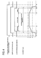
- FIG. 4 is a time chart showing the case where the opening/closing operation of the door 3 is normally conducted by the door opening/closing apparatus 5 for electrostatic painting in relation to (A) Activation of the door opening/closing apparatus 5, (B) Application of high voltage by the high-voltage generator 19, (C) Door opening/closing operation by the door opening/closing apparatus 5, and (D) Behaviors of a current value of the discharge current detected through the electrode pin 22.
- the opening/closing state of the door 3 is determined at each time t1 to t8 during operation of the door opening/closing apparatus 5.
- FIG. 4 the opening/closing state of the door 3 is determined at each time t1 to t8 during operation of the door opening/closing apparatus 5.
- the application of high voltage to the door opening/closing apparatus 5 is started at time t2 slightly before the time when the door 3 is opened (time t3) and then the application of high voltage is stopped at time t7 slightly after the time when the door 3 is closed (time t6).
- a current value of the discharge current detected through the electrode pin 22 rises just after the high voltage is applied at time t2.
- the current value increases as the third arm 17 is moved closer to the door 3 to open the door 3. Then, while the door 3 is open between times t4 and t5, the current value remains unchanged.
- the current value decreases as the third arm 17 is moved away from the door 3 between times t5 and t6. Just after the application of high voltage is stopped at time t7, the current value falls down.
- the current value of the discharge current detected through the electrode pin 22 properly changes between values a, b, and c as shown in FIG. 4 (D) in accordance with the opening/closing operation of the door shown in FIG. 4 (C) .
- the interference between the third arm 17 and the door 3 can be predicted, thereby monitoring the opening/closing state of the door 3 caused by the door opening/closing apparatus 5.
- FIG. 5 is a table showing determination logic for determining whether the opening/closing state of the door 3 is normal or abnormal.
- the current value not exceeding the upper limit "a” is determined to be "normal” and the current value exceeding the upper limit "a” is determined to be "abnormal".
- FIG. 6 is a time chart showing the case where the third arm 17 of the door opening/closing apparatus 5 abnormally moves closer to the door 3 for electrostatic painting in relation to (A) Activation of the door opening/closing apparatus 5, (B) Application of high voltage by the high-voltage generator 19, (C) Door opening/closing operation by the door opening/closing apparatus 5, (D) Behaviors of a current value of the discharge current detected through the electrode pin 22. As shown by a solid line in FIG. 6 (D) , while the door 3 is open from time t4 to time t5, if the current value exceeds the upper limit "a" as indicated by a circular solid line E1, the high-voltage controller 20 determines the door opening/closing operation is abnormal. A chain double-dashed line in FIG. 6 (D) indicates changes in current value in the normal case.
- FIG. 7 is a time chart showing the case where the third arm 17 of the door opening/closing apparatus 5 abnormally moves away from the door 3 for electrostatic painting in relation to (A) Activation of the door opening/closing apparatus 5, (B) Application of high voltage by the high-voltage generator 19, (C) Door opening/closing operation by the door opening/closing apparatus 5, (D) Behaviors of a current value of the discharge current detected through the electrode pin 22. As shown by a solid line in FIG.
- a chain double-dashed line in FIG. 7 (D) indicates changes in current value in the normal case.
- the high-voltage controller 20 monitors the positional relationship between the third arm 17 and the door 3, i.e., the opening/closing state of the door 3 by the door opening/closing apparatus 5 based on the discharge current detected through the electrode pin 22 and determines whether the opening/closing state is normal or abnormal.
- the door painting robot 4 and the door opening/closing apparatus 5 are operated in accordance with a previously set program to perform electrostatic painting on the door 3 as scheduled.
- the operations of the door painting robot 4 and the door opening/closing apparatus 5 have only to be immediately stopped to interrupt the electrostatic painting.
- the electrostatic painting can be properly performed with respect to the door 3 while the opening/closing state of the door 3 is monitored.
- the opening/closing hook 18 is provided with the position sensor 31 to detect the position of the door 3.
- the position sensor 31 detects the position of the door 3.
- the hook 18 can be precisely aligned with the position of the door 3 based on detection of the door 3 by the position sensor 31.
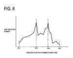
- the opening/closing hook 18 is horizontally moved along the upper part of the door 3 from a first position P1 on the left side to a second position P2 on the right side.
- the position sensor 31 is activated, thereby detecting the position of the glass groove 3c of the door 3.
- a relationship between a horizontal position of the hook 18 and a light reflection intensity detected by the position sensor 31 is shown as a graph in FIG. 8 .
- the light reflection intensity changes while exhibiting two peaks at two intermediate positions P3 and P4 between the first position P1 and the second position P2.
- One peak at the intermediate position P3 represents that the position sensor 31 reaches just above the top of the outer panel 3a in FIG. 3 and the other peak at the intermediate position P4 represents that the position sensor 31 reaches just above the top of the inner panel 3b in FIG. 3 .
- a section between the intermediate positions P3 and P4 can be determined as the position of the glass groove 3c.
- Such positional information detected by the position sensor 31 is fed back to the operation of the door opening/closing apparatus 5.
- the opening/closing hook 18 can therefore be reliably inserted and engaged in the glass groove 3c of the door 3.
- the position sensor 31 is placed in the opening/closing hook 18 and thus is protected from dust (stains). Since purge air is supplied into the opening/closing hook 18, the position sensor 31 can be further protected from dust (stains). In this embodiment, furthermore, since the position sensor 31 is an optical fiber sensor requiring no explosion-proof measure, no explosion-proof structure needs to be added. Consequently, the position sensor 31 can be placed in a smaller size in the opening/closing hook 18.
- the door 3 to be opened/closed horizontally is considered as an opening/closing object.
- the door opening/closing apparatus 5 for opening and closing the door 3 is configured to detect discharge current through the electrode pin 22 provided in the third arm 17 to determine the opening/closing state of the door 3.
- the opening/closing object may be a trunk cover or a bonnet (hood) of a vehicle body or a flip-up rear door of a vehicle body, which are opened and closed in a vertical direction.
- an opening/closing apparatus for opening and closing the trunk cover, bonnet, or flip-up door is configured to detect discharge current through an electrode pin to determine the opening/closing state of the trunk cover or the like. For instance, as shown in FIG.
- a robot having the same configuration as the aforementioned door painting robot 4 may be used as a door opening/closing apparatus 25 corresponding to an opening/closing means.
- a second arm 10 is made of resin and a high-voltage generator 19 is placed in the second arm 10.
- an electrode pin 22 and a right-angled opening/closing hook 26 made of resin serving as an engaging tool are provided respectively.
- This hook 26 is engaged with the trunk cover or the like and the second arm 10 is rotated upward and downward to open and close the trunk cover or the like in the vertical direction.
- the discharge current is detected through the electrode pin 22 and thus the opening/closing state of the trunk cover or the like can be determined.
- the door 3 is an opening/closing object.
- the door opening/closing apparatus 5 for opening and closing the door 3 is configured to detect the discharge current through the electrode pin 22 provided in the third arm 17 to determine the opening/closing state of the door 3.
- the door painting robot 4 may be configured such that the second arm 10 is made of resin and the high-voltage generator 19 is placed in the second arm 10, and a hook-shaped electrode pin 27 corresponding to a discharge current detecting means is provided at a free end of the second arm 10. Thus, the discharge current is detected through the electrode pin 27 to determine the positional relationship between the door 3 and the painting nozzle 11.
- this configuration may be arranged such that, after the positional relationship between the door 3 and the painting nozzle 11 is determined, the electrode pin 27 is withdrawn into the second arm 10 by use of a cylinder or the like in order to avoid interference between the electrode pin 27 and the door 3 when the painting nozzle 11 is to be freely operated.
- the opening/closing tool 13 and both the second arm 16 and the third arm 17 are applied with high voltage.
- An alternative is to apply high voltage only to the opening/closing tool 13 and the third arm 17.
- the opening/closing hook 18 is made of resin which is an insulating material.
- This opening/closing hook may be made of a conductive material with a resistor or a semi-conducting material.
- the conductive material with a resistor may include "resin containing carbon” and the semi-conducting material may include “polyurethane”.
- the resin which is an insulating material may be covered with fluorinated coating (e.g., "Teflon"(Registered Trademark)).
- the third arm 17 is provided with the electrode pin 22 and the wiring 23 as the discharge current detecting means.
- An alternative is to omit the electrode pin 22 and provide only the wiring 23.
- the third arm 17 itself acts as a means for detecting discharge current between the third arm 17 and the door 3.
- the present invention can provide an electrostatic painting apparatus for electrostatically painting an opening/closing object provided in an object to be painted by a painting means while opening and closing the opening/closing object by an opening/closing means, in which prediction of interference with the opening/closing object is enabled without adding a special explosion-proof structure.
- the present invention can also provides an electrostatic painting method for electrostatically painting an opening/closing object provided in an object to be painted by a painting means while opening and closing the opening/closing object by an opening/closing means, in which prediction of interference with the opening/closing object is enabled without adding a special explosion-proof structure.
Landscapes
- Engineering & Computer Science (AREA)
- Robotics (AREA)
- Electrostatic Spraying Apparatus (AREA)
- Spray Control Apparatus (AREA)
- Application Of Or Painting With Fluid Materials (AREA)
Applications Claiming Priority (2)
| Application Number | Priority Date | Filing Date | Title |
|---|---|---|---|
| JP2007198731A JP4967903B2 (ja) | 2007-07-31 | 2007-07-31 | 静電塗装装置及び静電塗装方法 |
| PCT/JP2008/063085 WO2009016986A1 (ja) | 2007-07-31 | 2008-07-15 | 静電塗装装置及び静電塗装方法 |
Publications (3)
| Publication Number | Publication Date |
|---|---|
| EP2184112A1 true EP2184112A1 (de) | 2010-05-12 |
| EP2184112A4 EP2184112A4 (de) | 2010-08-18 |
| EP2184112B1 EP2184112B1 (de) | 2013-01-02 |
Family
ID=40304219
Family Applications (1)
| Application Number | Title | Priority Date | Filing Date |
|---|---|---|---|
| EP08791372A Not-in-force EP2184112B1 (de) | 2007-07-31 | 2008-07-15 | Elektrostatische lackiervorrichtung und elektrostatisches lackierverfahren |
Country Status (6)
| Country | Link |
|---|---|
| US (1) | US8329259B2 (de) |
| EP (1) | EP2184112B1 (de) |
| JP (1) | JP4967903B2 (de) |
| CN (1) | CN101801541B (de) |
| TW (1) | TW200911381A (de) |
| WO (1) | WO2009016986A1 (de) |
Cited By (1)
| Publication number | Priority date | Publication date | Assignee | Title |
|---|---|---|---|---|
| EP2556929A1 (de) * | 2011-08-10 | 2013-02-13 | Kabushiki Kaisha Yaskawa Denki | Anstreichsystem |
Families Citing this family (17)
| Publication number | Priority date | Publication date | Assignee | Title |
|---|---|---|---|---|
| JP4967903B2 (ja) * | 2007-07-31 | 2012-07-04 | トヨタ自動車株式会社 | 静電塗装装置及び静電塗装方法 |
| JP4812871B2 (ja) | 2009-10-21 | 2011-11-09 | トヨタ自動車株式会社 | 塗料充填装置 |
| JP4850944B2 (ja) * | 2009-10-21 | 2012-01-11 | トヨタ自動車株式会社 | 塗料供給方法 |
| WO2011055766A1 (ja) * | 2009-11-06 | 2011-05-12 | 本田技研工業株式会社 | 塗装システム |
| JP5474504B2 (ja) * | 2009-11-18 | 2014-04-16 | トヨタ自動車株式会社 | 静電塗装装置および静電塗装装置の塗料汚れ防止方法 |
| JP5738562B2 (ja) * | 2010-09-27 | 2015-06-24 | トヨタ自動車株式会社 | 静電塗装装置 |
| US8950050B2 (en) * | 2010-12-28 | 2015-02-10 | Honda Motor Co., Ltd. | Vehicle body door opening method and device, door removing device and method, door holding device and method, and socket |
| CN102921581B (zh) * | 2011-08-09 | 2015-07-22 | 株式会社安川电机 | 涂装系统和门开/关机器人的开/关手 |
| DE102014017855A1 (de) * | 2014-12-03 | 2016-06-09 | Dürr Systems GmbH | Handhabungseinrichtung zum Öffnen einer Klappe und entsprechendes Verfahren |
| JP6677190B2 (ja) | 2017-02-09 | 2020-04-08 | 株式会社安川電機 | 塗装システムおよび固定式操作ロボット |
| DE102017216276B4 (de) * | 2017-09-14 | 2025-01-23 | Bayerische Motoren Werke Aktiengesellschaft | Verfahren zum Ermitteln einer Schwenkstellung eines an einem Aufbau eines Fahrzeugs gehaltenen Flügelelements, insbesondere einer Tür oder einer Klappe |
| DE102018008884A1 (de) * | 2018-11-07 | 2020-05-07 | ese-robotics GmbH | Zentrierkörper und Verfahren zu dessen Ausrichtung |
| US11285623B2 (en) * | 2020-02-04 | 2022-03-29 | Toyota Motor Engineering & Manufacturing North America, Inc. | Fiber optic paint robot tool |
| DE102021101027A1 (de) * | 2021-01-19 | 2022-07-21 | Dürr Systems Ag | Beschichtungseinrichtung, insbesondere Lackierroboter |
| US20230090908A1 (en) * | 2021-09-23 | 2023-03-23 | GM Global Technology Operations LLC | Paint spray nozzle for a paint spray system |
| JP7824099B2 (ja) * | 2022-02-28 | 2026-03-04 | 株式会社安川電機 | ロボット装置、及び、制御方法 |
| FR3165570A1 (fr) * | 2024-08-13 | 2026-02-20 | Stellantis Auto Sas | Outil destiné à équiper une extrémité d’un bras poly-articulé d’un robot |
Family Cites Families (19)
| Publication number | Priority date | Publication date | Assignee | Title |
|---|---|---|---|---|
| JPS59109268A (ja) | 1982-12-15 | 1984-06-23 | Asahi Okuma Ind Co Ltd | 静電塗装機 |
| JPS59142182A (ja) | 1983-02-02 | 1984-08-15 | Fuji Photo Film Co Ltd | 記録材料 |
| JPS59142182U (ja) * | 1983-03-15 | 1984-09-22 | 株式会社椿本チエイン | ドア自動開閉装置のハンド部の構造 |
| DE3786712D1 (de) | 1986-06-16 | 1993-09-02 | Siemens Ag | Sensoranordnung zur regelung implantierbarer koerperersatzteile. |
| JPS63798U (de) * | 1986-06-19 | 1988-01-06 | ||
| JPH01155191A (ja) | 1987-12-09 | 1989-06-19 | Nippon Steel Corp | 耐火ライニングの補修方法 |
| JPH01155191U (de) * | 1988-04-14 | 1989-10-25 | ||
| JPH04108553A (ja) * | 1990-07-20 | 1992-04-09 | Kobe Steel Ltd | 自動車の塗装システム |
| DE4214863A1 (de) | 1992-05-05 | 1993-11-11 | Kuka Schweissanlagen & Roboter | Verfahren und Vorrichtung zur Montage von Türen in Fahrzeugkarosserien |
| JPH06142607A (ja) * | 1992-11-05 | 1994-05-24 | Honda Motor Co Ltd | 自動車のドア回りの塗装方法 |
| JPH0718542A (ja) | 1993-06-29 | 1995-01-20 | Micron Kiki Kk | 緯糸送り出し装置の自動緯糸巻き掛け装置 |
| JP3636384B2 (ja) * | 1994-12-12 | 2005-04-06 | 川崎重工業株式会社 | 自動車塗装システム |
| US5941679A (en) | 1997-10-27 | 1999-08-24 | Fanuc Robotics North America, Inc. | Automotive door opening robot assembly |
| FR2815555B1 (fr) * | 2000-10-19 | 2003-07-18 | Sames Technologies | Dispositif et procede d'alimentation de projecteurs et installation de projection equipee d'un tel dispositif |
| FR2835450B1 (fr) * | 2002-02-06 | 2004-06-04 | Sames Technologies | Installation de projection de produit de revetement et procede de nettoyage d'une telle installation |
| JP4108553B2 (ja) * | 2003-07-01 | 2008-06-25 | 株式会社日立製作所 | 光情報記録媒体及び光情報記録装置 |
| JP2008514504A (ja) * | 2004-09-30 | 2008-05-08 | アーベーベー アーエス | 産業用ロボットに使用されるドア開閉機構 |
| JP4645375B2 (ja) * | 2005-09-08 | 2011-03-09 | トヨタ自動車株式会社 | 静電塗装装置 |
| JP4967903B2 (ja) * | 2007-07-31 | 2012-07-04 | トヨタ自動車株式会社 | 静電塗装装置及び静電塗装方法 |
-
2007
- 2007-07-31 JP JP2007198731A patent/JP4967903B2/ja active Active
-
2008
- 2008-07-15 EP EP08791372A patent/EP2184112B1/de not_active Not-in-force
- 2008-07-15 US US12/666,884 patent/US8329259B2/en not_active Expired - Fee Related
- 2008-07-15 CN CN2008801012314A patent/CN101801541B/zh not_active Expired - Fee Related
- 2008-07-15 WO PCT/JP2008/063085 patent/WO2009016986A1/ja not_active Ceased
- 2008-07-30 TW TW097128865A patent/TW200911381A/zh not_active IP Right Cessation
Cited By (1)
| Publication number | Priority date | Publication date | Assignee | Title |
|---|---|---|---|---|
| EP2556929A1 (de) * | 2011-08-10 | 2013-02-13 | Kabushiki Kaisha Yaskawa Denki | Anstreichsystem |
Also Published As
| Publication number | Publication date |
|---|---|
| US20110020561A1 (en) | 2011-01-27 |
| EP2184112B1 (de) | 2013-01-02 |
| TW200911381A (en) | 2009-03-16 |
| TWI344393B (de) | 2011-07-01 |
| WO2009016986A1 (ja) | 2009-02-05 |
| JP4967903B2 (ja) | 2012-07-04 |
| JP2009034566A (ja) | 2009-02-19 |
| EP2184112A4 (de) | 2010-08-18 |
| CN101801541B (zh) | 2012-10-10 |
| US8329259B2 (en) | 2012-12-11 |
| CN101801541A (zh) | 2010-08-11 |
Similar Documents
| Publication | Publication Date | Title |
|---|---|---|
| EP2184112B1 (de) | Elektrostatische lackiervorrichtung und elektrostatisches lackierverfahren | |
| CN100512976C (zh) | 静电喷涂装置 | |
| KR102546594B1 (ko) | 분체도장 시스템 | |
| JP2009034565A (ja) | 静電塗装装置及び静電塗装方法 | |
| KR101468577B1 (ko) | 정전 도장방법 및 정전 도장용 건 | |
| EP0945183A2 (de) | Sicheres Laden eines nicht-isolierenden Zerstäubers | |
| KR20170106960A (ko) | 절연 코팅을 포함하는 벨 컵 또는 안내 공기 링 | |
| JPWO2005079996A1 (ja) | 回転霧化頭型塗装装置 | |
| CN117753578A (zh) | 静电涂装设备 | |
| KR20110039232A (ko) | 작업물을 정전기적으로 코팅하는 장치 및 그 장치의 오염을 감소시키는 방법 | |
| JPH10109054A (ja) | 静電塗装装置 | |
| CN106413910B (zh) | 具有外部充电点的静电喷枪 | |
| JP3335937B2 (ja) | 静電塗装の高電圧制御方法 | |
| JP2009183810A (ja) | 静電作用を利用した塗装方法 | |
| KR100774326B1 (ko) | 벨 도장기 | |
| JP7596956B2 (ja) | 絶縁体の塗装方法および塗装装置 | |
| JP4347753B2 (ja) | 静電塗装用スプレーガン | |
| JP3739144B2 (ja) | 自動塗装装置 | |
| KR101231417B1 (ko) | 전착도장의 에어포켓 제거 장치 | |
| JPH0531408A (ja) | 静電塗装におけるスパーク防止装置 | |
| JP5600574B2 (ja) | 静電塗装装置 | |
| JPH10235232A (ja) | 静電塗装ガンの洗浄装置 | |
| JPS6238262A (ja) | 塗装装置 | |
| JP2006263658A (ja) | 自動車ボデーの塗装方法とそれに用いる塗装装置 | |
| JPH07213959A (ja) | ワーク塗装装置 |
Legal Events
| Date | Code | Title | Description |
|---|---|---|---|
| PUAI | Public reference made under article 153(3) epc to a published international application that has entered the european phase |
Free format text: ORIGINAL CODE: 0009012 |
|
| 17P | Request for examination filed |
Effective date: 20100301 |
|
| AK | Designated contracting states |
Kind code of ref document: A1 Designated state(s): AT BE BG CH CY CZ DE DK EE ES FI FR GB GR HR HU IE IS IT LI LT LU LV MC MT NL NO PL PT RO SE SI SK TR |
|
| AX | Request for extension of the european patent |
Extension state: AL BA MK RS |
|
| A4 | Supplementary search report drawn up and despatched |
Effective date: 20100715 |
|
| DAX | Request for extension of the european patent (deleted) | ||
| REG | Reference to a national code |
Ref country code: DE Ref legal event code: R079 Ref document number: 602008021410 Country of ref document: DE Free format text: PREVIOUS MAIN CLASS: B05B0012000000 Ipc: B05B0012080000 |
|
| GRAP | Despatch of communication of intention to grant a patent |
Free format text: ORIGINAL CODE: EPIDOSNIGR1 |
|
| RIC1 | Information provided on ipc code assigned before grant |
Ipc: B05B 13/04 20060101ALI20120703BHEP Ipc: B05B 12/08 20060101AFI20120703BHEP Ipc: B05B 13/02 20060101ALI20120703BHEP |
|
| GRAS | Grant fee paid |
Free format text: ORIGINAL CODE: EPIDOSNIGR3 |
|
| GRAA | (expected) grant |
Free format text: ORIGINAL CODE: 0009210 |
|
| AK | Designated contracting states |
Kind code of ref document: B1 Designated state(s): AT BE BG CH CY CZ DE DK EE ES FI FR GB GR HR HU IE IS IT LI LT LU LV MC MT NL NO PL PT RO SE SI SK TR |
|
| REG | Reference to a national code |
Ref country code: GB Ref legal event code: FG4D |
|
| REG | Reference to a national code |
Ref country code: AT Ref legal event code: REF Ref document number: 591284 Country of ref document: AT Kind code of ref document: T Effective date: 20130115 Ref country code: CH Ref legal event code: EP |
|
| RIN2 | Information on inventor provided after grant (corrected) |
Inventor name: TANI, SHINJI |
|
| RAP2 | Party data changed (patent owner data changed or rights of a patent transferred) |
Owner name: TOYOTA JIDOSHA KABUSHIKI KAISHA |
|
| RIN2 | Information on inventor provided after grant (corrected) |
Inventor name: TANI, SHINJI |
|
| REG | Reference to a national code |
Ref country code: IE Ref legal event code: FG4D |
|
| RAP2 | Party data changed (patent owner data changed or rights of a patent transferred) |
Owner name: TOYOTA JIDOSHA KABUSHIKI KAISHA |
|
| REG | Reference to a national code |
Ref country code: DE Ref legal event code: R096 Ref document number: 602008021410 Country of ref document: DE Effective date: 20130228 |
|
| REG | Reference to a national code |
Ref country code: AT Ref legal event code: MK05 Ref document number: 591284 Country of ref document: AT Kind code of ref document: T Effective date: 20130102 |
|
| REG | Reference to a national code |
Ref country code: NL Ref legal event code: VDEP Effective date: 20130102 |
|
| PG25 | Lapsed in a contracting state [announced via postgrant information from national office to epo] |
Ref country code: SI Free format text: LAPSE BECAUSE OF FAILURE TO SUBMIT A TRANSLATION OF THE DESCRIPTION OR TO PAY THE FEE WITHIN THE PRESCRIBED TIME-LIMIT Effective date: 20130102 |
|
| REG | Reference to a national code |
Ref country code: LT Ref legal event code: MG4D |
|
| PG25 | Lapsed in a contracting state [announced via postgrant information from national office to epo] |
Ref country code: LT Free format text: LAPSE BECAUSE OF FAILURE TO SUBMIT A TRANSLATION OF THE DESCRIPTION OR TO PAY THE FEE WITHIN THE PRESCRIBED TIME-LIMIT Effective date: 20130102 Ref country code: BG Free format text: LAPSE BECAUSE OF FAILURE TO SUBMIT A TRANSLATION OF THE DESCRIPTION OR TO PAY THE FEE WITHIN THE PRESCRIBED TIME-LIMIT Effective date: 20130402 Ref country code: ES Free format text: LAPSE BECAUSE OF FAILURE TO SUBMIT A TRANSLATION OF THE DESCRIPTION OR TO PAY THE FEE WITHIN THE PRESCRIBED TIME-LIMIT Effective date: 20130413 Ref country code: IS Free format text: LAPSE BECAUSE OF FAILURE TO SUBMIT A TRANSLATION OF THE DESCRIPTION OR TO PAY THE FEE WITHIN THE PRESCRIBED TIME-LIMIT Effective date: 20130502 Ref country code: CZ Free format text: LAPSE BECAUSE OF FAILURE TO SUBMIT A TRANSLATION OF THE DESCRIPTION OR TO PAY THE FEE WITHIN THE PRESCRIBED TIME-LIMIT Effective date: 20130102 Ref country code: NO Free format text: LAPSE BECAUSE OF FAILURE TO SUBMIT A TRANSLATION OF THE DESCRIPTION OR TO PAY THE FEE WITHIN THE PRESCRIBED TIME-LIMIT Effective date: 20130402 Ref country code: BE Free format text: LAPSE BECAUSE OF FAILURE TO SUBMIT A TRANSLATION OF THE DESCRIPTION OR TO PAY THE FEE WITHIN THE PRESCRIBED TIME-LIMIT Effective date: 20130102 Ref country code: AT Free format text: LAPSE BECAUSE OF FAILURE TO SUBMIT A TRANSLATION OF THE DESCRIPTION OR TO PAY THE FEE WITHIN THE PRESCRIBED TIME-LIMIT Effective date: 20130102 Ref country code: SE Free format text: LAPSE BECAUSE OF FAILURE TO SUBMIT A TRANSLATION OF THE DESCRIPTION OR TO PAY THE FEE WITHIN THE PRESCRIBED TIME-LIMIT Effective date: 20130102 |
|
| PG25 | Lapsed in a contracting state [announced via postgrant information from national office to epo] |
Ref country code: GR Free format text: LAPSE BECAUSE OF FAILURE TO SUBMIT A TRANSLATION OF THE DESCRIPTION OR TO PAY THE FEE WITHIN THE PRESCRIBED TIME-LIMIT Effective date: 20130403 Ref country code: FI Free format text: LAPSE BECAUSE OF FAILURE TO SUBMIT A TRANSLATION OF THE DESCRIPTION OR TO PAY THE FEE WITHIN THE PRESCRIBED TIME-LIMIT Effective date: 20130102 Ref country code: PL Free format text: LAPSE BECAUSE OF FAILURE TO SUBMIT A TRANSLATION OF THE DESCRIPTION OR TO PAY THE FEE WITHIN THE PRESCRIBED TIME-LIMIT Effective date: 20130102 Ref country code: LV Free format text: LAPSE BECAUSE OF FAILURE TO SUBMIT A TRANSLATION OF THE DESCRIPTION OR TO PAY THE FEE WITHIN THE PRESCRIBED TIME-LIMIT Effective date: 20130102 Ref country code: PT Free format text: LAPSE BECAUSE OF FAILURE TO SUBMIT A TRANSLATION OF THE DESCRIPTION OR TO PAY THE FEE WITHIN THE PRESCRIBED TIME-LIMIT Effective date: 20130502 Ref country code: NL Free format text: LAPSE BECAUSE OF FAILURE TO SUBMIT A TRANSLATION OF THE DESCRIPTION OR TO PAY THE FEE WITHIN THE PRESCRIBED TIME-LIMIT Effective date: 20130102 |
|
| PG25 | Lapsed in a contracting state [announced via postgrant information from national office to epo] |
Ref country code: HR Free format text: LAPSE BECAUSE OF FAILURE TO SUBMIT A TRANSLATION OF THE DESCRIPTION OR TO PAY THE FEE WITHIN THE PRESCRIBED TIME-LIMIT Effective date: 20130102 |
|
| PG25 | Lapsed in a contracting state [announced via postgrant information from national office to epo] |
Ref country code: SK Free format text: LAPSE BECAUSE OF FAILURE TO SUBMIT A TRANSLATION OF THE DESCRIPTION OR TO PAY THE FEE WITHIN THE PRESCRIBED TIME-LIMIT Effective date: 20130102 Ref country code: RO Free format text: LAPSE BECAUSE OF FAILURE TO SUBMIT A TRANSLATION OF THE DESCRIPTION OR TO PAY THE FEE WITHIN THE PRESCRIBED TIME-LIMIT Effective date: 20130102 Ref country code: DK Free format text: LAPSE BECAUSE OF FAILURE TO SUBMIT A TRANSLATION OF THE DESCRIPTION OR TO PAY THE FEE WITHIN THE PRESCRIBED TIME-LIMIT Effective date: 20130102 Ref country code: EE Free format text: LAPSE BECAUSE OF FAILURE TO SUBMIT A TRANSLATION OF THE DESCRIPTION OR TO PAY THE FEE WITHIN THE PRESCRIBED TIME-LIMIT Effective date: 20130102 |
|
| PLBE | No opposition filed within time limit |
Free format text: ORIGINAL CODE: 0009261 |
|
| STAA | Information on the status of an ep patent application or granted ep patent |
Free format text: STATUS: NO OPPOSITION FILED WITHIN TIME LIMIT |
|
| PG25 | Lapsed in a contracting state [announced via postgrant information from national office to epo] |
Ref country code: CY Free format text: LAPSE BECAUSE OF FAILURE TO SUBMIT A TRANSLATION OF THE DESCRIPTION OR TO PAY THE FEE WITHIN THE PRESCRIBED TIME-LIMIT Effective date: 20130102 |
|
| 26N | No opposition filed |
Effective date: 20131003 |
|
| PG25 | Lapsed in a contracting state [announced via postgrant information from national office to epo] |
Ref country code: IT Free format text: LAPSE BECAUSE OF FAILURE TO SUBMIT A TRANSLATION OF THE DESCRIPTION OR TO PAY THE FEE WITHIN THE PRESCRIBED TIME-LIMIT Effective date: 20130102 |
|
| REG | Reference to a national code |
Ref country code: DE Ref legal event code: R097 Ref document number: 602008021410 Country of ref document: DE Effective date: 20131003 |
|
| PG25 | Lapsed in a contracting state [announced via postgrant information from national office to epo] |
Ref country code: MC Free format text: LAPSE BECAUSE OF FAILURE TO SUBMIT A TRANSLATION OF THE DESCRIPTION OR TO PAY THE FEE WITHIN THE PRESCRIBED TIME-LIMIT Effective date: 20130102 |
|
| REG | Reference to a national code |
Ref country code: CH Ref legal event code: PL |
|
| REG | Reference to a national code |
Ref country code: IE Ref legal event code: MM4A |
|
| PG25 | Lapsed in a contracting state [announced via postgrant information from national office to epo] |
Ref country code: LI Free format text: LAPSE BECAUSE OF NON-PAYMENT OF DUE FEES Effective date: 20130731 Ref country code: CH Free format text: LAPSE BECAUSE OF NON-PAYMENT OF DUE FEES Effective date: 20130731 |
|
| PG25 | Lapsed in a contracting state [announced via postgrant information from national office to epo] |
Ref country code: IE Free format text: LAPSE BECAUSE OF NON-PAYMENT OF DUE FEES Effective date: 20130715 |
|
| REG | Reference to a national code |
Ref country code: DE Ref legal event code: R084 Ref document number: 602008021410 Country of ref document: DE |
|
| REG | Reference to a national code |
Ref country code: GB Ref legal event code: 746 Effective date: 20150424 |
|
| REG | Reference to a national code |
Ref country code: DE Ref legal event code: R084 Ref document number: 602008021410 Country of ref document: DE Effective date: 20150417 |
|
| PG25 | Lapsed in a contracting state [announced via postgrant information from national office to epo] |
Ref country code: TR Free format text: LAPSE BECAUSE OF FAILURE TO SUBMIT A TRANSLATION OF THE DESCRIPTION OR TO PAY THE FEE WITHIN THE PRESCRIBED TIME-LIMIT Effective date: 20130102 Ref country code: MT Free format text: LAPSE BECAUSE OF FAILURE TO SUBMIT A TRANSLATION OF THE DESCRIPTION OR TO PAY THE FEE WITHIN THE PRESCRIBED TIME-LIMIT Effective date: 20130102 |
|
| PG25 | Lapsed in a contracting state [announced via postgrant information from national office to epo] |
Ref country code: HU Free format text: LAPSE BECAUSE OF FAILURE TO SUBMIT A TRANSLATION OF THE DESCRIPTION OR TO PAY THE FEE WITHIN THE PRESCRIBED TIME-LIMIT; INVALID AB INITIO Effective date: 20080715 Ref country code: LU Free format text: LAPSE BECAUSE OF NON-PAYMENT OF DUE FEES Effective date: 20130715 |
|
| REG | Reference to a national code |
Ref country code: FR Ref legal event code: PLFP Year of fee payment: 9 |
|
| REG | Reference to a national code |
Ref country code: FR Ref legal event code: PLFP Year of fee payment: 10 |
|
| REG | Reference to a national code |
Ref country code: FR Ref legal event code: PLFP Year of fee payment: 11 |
|
| PGFP | Annual fee paid to national office [announced via postgrant information from national office to epo] |
Ref country code: FR Payment date: 20190619 Year of fee payment: 12 |
|
| PGFP | Annual fee paid to national office [announced via postgrant information from national office to epo] |
Ref country code: DE Payment date: 20190702 Year of fee payment: 12 |
|
| PGFP | Annual fee paid to national office [announced via postgrant information from national office to epo] |
Ref country code: GB Payment date: 20190710 Year of fee payment: 12 |
|
| REG | Reference to a national code |
Ref country code: DE Ref legal event code: R119 Ref document number: 602008021410 Country of ref document: DE |
|
| GBPC | Gb: european patent ceased through non-payment of renewal fee |
Effective date: 20200715 |
|
| PG25 | Lapsed in a contracting state [announced via postgrant information from national office to epo] |
Ref country code: FR Free format text: LAPSE BECAUSE OF NON-PAYMENT OF DUE FEES Effective date: 20200731 Ref country code: GB Free format text: LAPSE BECAUSE OF NON-PAYMENT OF DUE FEES Effective date: 20200715 |
|
| PG25 | Lapsed in a contracting state [announced via postgrant information from national office to epo] |
Ref country code: DE Free format text: LAPSE BECAUSE OF NON-PAYMENT OF DUE FEES Effective date: 20210202 |