EP2189723A1 - Chambre de combustion de turbine à gaz - Google Patents
Chambre de combustion de turbine à gaz Download PDFInfo
- Publication number
- EP2189723A1 EP2189723A1 EP09176855A EP09176855A EP2189723A1 EP 2189723 A1 EP2189723 A1 EP 2189723A1 EP 09176855 A EP09176855 A EP 09176855A EP 09176855 A EP09176855 A EP 09176855A EP 2189723 A1 EP2189723 A1 EP 2189723A1
- Authority
- EP
- European Patent Office
- Prior art keywords
- combustion chamber
- chamber wall
- hot gas
- wall
- gas housing
- Prior art date
- Legal status (The legal status is an assumption and is not a legal conclusion. Google has not performed a legal analysis and makes no representation as to the accuracy of the status listed.)
- Granted
Links
Images



Classifications
-
- F—MECHANICAL ENGINEERING; LIGHTING; HEATING; WEAPONS; BLASTING
- F02—COMBUSTION ENGINES; HOT-GAS OR COMBUSTION-PRODUCT ENGINE PLANTS
- F02C—GAS-TURBINE PLANTS; AIR INTAKES FOR JET-PROPULSION PLANTS; CONTROLLING FUEL SUPPLY IN AIR-BREATHING JET-PROPULSION PLANTS
- F02C3/00—Gas-turbine plants characterised by the use of combustion products as the working fluid
- F02C3/14—Gas-turbine plants characterised by the use of combustion products as the working fluid characterised by the arrangement of the combustion chamber in the plant
-
- F—MECHANICAL ENGINEERING; LIGHTING; HEATING; WEAPONS; BLASTING
- F23—COMBUSTION APPARATUS; COMBUSTION PROCESSES
- F23R—GENERATING COMBUSTION PRODUCTS OF HIGH PRESSURE OR HIGH VELOCITY, e.g. GAS-TURBINE COMBUSTION CHAMBERS
- F23R3/00—Continuous combustion chambers using liquid or gaseous fuel
- F23R3/02—Continuous combustion chambers using liquid or gaseous fuel characterised by the air-flow or gas-flow configuration
- F23R3/04—Air inlet arrangements
- F23R3/06—Arrangement of apertures along the flame tube
- F23R3/08—Arrangement of apertures along the flame tube between annular flame tube sections, e.g. flame tubes with telescopic sections
-
- F—MECHANICAL ENGINEERING; LIGHTING; HEATING; WEAPONS; BLASTING
- F02—COMBUSTION ENGINES; HOT-GAS OR COMBUSTION-PRODUCT ENGINE PLANTS
- F02C—GAS-TURBINE PLANTS; AIR INTAKES FOR JET-PROPULSION PLANTS; CONTROLLING FUEL SUPPLY IN AIR-BREATHING JET-PROPULSION PLANTS
- F02C7/00—Features, components parts, details or accessories, not provided for in, or of interest apart form groups F02C1/00 - F02C6/00; Air intakes for jet-propulsion plants
-
- F—MECHANICAL ENGINEERING; LIGHTING; HEATING; WEAPONS; BLASTING
- F23—COMBUSTION APPARATUS; COMBUSTION PROCESSES
- F23R—GENERATING COMBUSTION PRODUCTS OF HIGH PRESSURE OR HIGH VELOCITY, e.g. GAS-TURBINE COMBUSTION CHAMBERS
- F23R3/00—Continuous combustion chambers using liquid or gaseous fuel
- F23R3/002—Wall structures
-
- F—MECHANICAL ENGINEERING; LIGHTING; HEATING; WEAPONS; BLASTING
- F23—COMBUSTION APPARATUS; COMBUSTION PROCESSES
- F23R—GENERATING COMBUSTION PRODUCTS OF HIGH PRESSURE OR HIGH VELOCITY, e.g. GAS-TURBINE COMBUSTION CHAMBERS
- F23R3/00—Continuous combustion chambers using liquid or gaseous fuel
- F23R3/42—Continuous combustion chambers using liquid or gaseous fuel characterised by the arrangement or form of the flame tubes or combustion chambers
-
- F—MECHANICAL ENGINEERING; LIGHTING; HEATING; WEAPONS; BLASTING
- F23—COMBUSTION APPARATUS; COMBUSTION PROCESSES
- F23R—GENERATING COMBUSTION PRODUCTS OF HIGH PRESSURE OR HIGH VELOCITY, e.g. GAS-TURBINE COMBUSTION CHAMBERS
- F23R2900/00—Special features of, or arrangements for continuous combustion chambers; Combustion processes therefor
- F23R2900/00012—Details of sealing devices
Definitions
- the invention relates to a combustion chamber arrangement for operating a gas turbine having a combustion chamber wall which comprises the combustion chamber space, according to the preamble of claim 1.
- a combustion chamber arrangement of the above type in which the combustion chamber wall overlaps on the outlet side in a hot gas housing through which the hot gases formed within the combustion chamber are fed to a gas turbine stage, thereby avoiding mechanical stresses between the combustion chamber wall and the hot gas housing, due to thermally different material expansion coefficients in that the combustion chamber wall opens into the hot gas housing with a radial clearance and encloses with it a gap extending over a specific axial region.
- combustion chamber arrangements are used, for example, in conjunction with so-called silo burners, for their detailed explanation, representative of the DE 42 23 828 A1 is referenced.
- combustion chamber arrangements are found in annular combustion chambers, which provide a plurality of star-shaped arranged around the rotor assembly of a gas turbine plant elongated individual combustion chambers, each of which is fired by a burner burner or a burner assembly.
- the downstream ends of the individual combustion chambers each open into a hot gas housing which feeds the hot gases into a first expansion stage of the gas turbine plant provided coaxially along the rotor arrangement.
- Representative is on the DE 196 15 910 B4 directed.
- the partial connection section between the combustion chamber wall 1 and the hot gas housing 2 is illustrated in greater detail in a schematic representation of the partial longitudinal section illustration. It is assumed that the combustion chamber wall 1 and the hot gas housing 2 which adjoins the combustion chamber wall 1 downstream of the combustion chamber wall are largely cylindrical and rotationally symmetrical about the axis A. Further suppose that upstream to the in Fig. 2 a burner arrangement for firing the combustion chamber 3 is provided, in which hot gases form, which propagate along the flow direction S and on the in Fig. 2 illustrated combustion chamber wall edge 4 to flow into the hot gas housing 2, which directs the hot gases downstream in a gas turbine stage not shown for targeted expansion.
- the combustion chamber wall 1 opens with its free-ending combustion chamber wall edge 4 with an axial overlap 5 within the hot gas housing 2, wherein the combustion chamber wall 1 relative to the hot gas housing 2 has a radial distance 6.
- the hot gas housing 2 For attachment of the annular seal 9, the hot gas housing 2 provides at its upstream end in the circumferential direction around the hot gas housing 2 arranged distributed, single collar-like fastening means 7, which are fixedly connected on one side with the hot gas housing 2, preferably via a welded joint 8.
- the annular seal is largely characterized by a ring which, respectively, a temperature-dependent dilatation. Restriction possible.
- the individual collar-shaped fastening means 7 are in engagement with this annular seal 9, which completely surrounds the outside of the combustion chamber wall 1 in the circumferential direction and is joined to the latter in such a manner that the annular seal 9 experiences a seat axially fixed in relation to the combustion chamber wall 1.
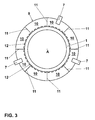
- FIG. 3 an axial view is shown on the voltage applied to the combustion chamber wall 1 annular seal 9.
- This in turn consists of a plurality of individual, so-called sealing segments 10, which are joined together in the circumferential direction at the ends in pairs via connecting structures 11 to each other.
- cooling air K enters the annular space region 13, which is bounded radially by the axially mutually overlapping combustion chamber wall 1 and the hot gas housing 2. Due to the near-wall inflow of the cooling air K along the inner wall of the hot gas housing 2 is formed at this a film cooling, by which the hot gas can be effectively cooled against the high temperature level of the hot gases.
- the invention aims to remedy this situation.
- the invention has the object of developing a combustion chamber arrangement of the aforementioned type such that measures are to be taken by which the thermally induced damage to the hot gas housing inner wall to be avoided.
- measures are to be taken by which the thermally induced damage to the hot gas housing inner wall to be avoided.
- it is necessary to look for measures with which the periodically recurring local overheating points can be effectively suppressed.
- Of particular interest is to realize the necessary modifications largely without the combustion process and the overall efficiency of the gas turbine plant reducing losses.
- a combustion chamber arrangement according to the features of the preamble of claim 1 for the purpose of effective removal of overheating associated with the periodically recurring local overheating points on the inner wall of the hot gas housing 2.
- the development according to the invention is characterized in that the combustion chamber wall edge is such is formed profiled, that in case of axial overflow of the combustion chamber wall edge of a directed axially through the flow channels in the annular space area cooling air flow, so that the same cooling air flow undergoes a targeted by the profiling targeted location inflow.
- the flow initiated by the profiling of the combustion chamber wall edge leads to a lasting disturbance of an evolving diffuser effect with respect to the cooling air flow which flows axially through the flow channels of the annular seal 9 into the annular space region, which provides film cooling of the inner wall of the hot gas housing 2 downstream the inclination of the hitherto forming recirculation of hot gas components around the combustion chamber wall edge in the direction of the annular space region is effectively suppressed, as a result of which the local overheating problem can be effectively counteracted in the context of the overheating points that repeatedly form there.
- Such leakage flows are due to cool air components which are able to pass through the annular seal 9 through cracks or gaps in the region of the respective connection structures, ie those regions in which two adjacent belt segments are connected to one another in the circumferential direction to the outside of the combustion chamber wall.
- it is necessary to match and form the joint contours in the area of the connection structure so that the gaps existing in the area of the connection structures are reduced to a minimum.
- This relates on the one hand to all axially extending surface regions, along which two adjacent sealing segments 10 each come into contact with each other via their connecting structure, but on the other hand, in particular the radially extending joining regions, as will be explained in more detail below with reference to a concrete embodiment.
- a further possibility for reducing the hot gas portions penetrating into the annular space region due to recirculation flows provides for the provision of a plurality of radially oriented passageways through the hot gas housing in the region of the above-described rim wall 15 or at the upstream end of the hot gas housing which is uniform in the circumferential direction around the hot gas housing are arranged distributed. Through each of the individual passage channels, cooling air flowing from outside to inside, radially or quasi-radially flowing into the annular space between the hot gas housing and the combustion chamber wall is fed.
- such a cooling air feed also has an influence on the film cooling formed along the inner wall of the hot gas housing, so that a finely metered setting by the individual Passage channels radially into the interior space area directed cooling air flow is to make, on the one hand to avoid the disturbing recirculation flow, on the other hand to leave the film air cooling forming as uninfluenced.
- Fig. 1 the downstream end of the combustion chamber wall 1 is shown with the end-side combustion chamber wall edge 4. It is assumed that the inner wall 16 of the combustion chamber wall 1 faces the hot gas flow S.
- the combustion chamber wall edge 4 has a chamfer with a chamfer surface 17 which faces the inner wall of the hot gas housing 2 and encloses an acute angle ⁇ with the remaining combustion chamber wall 1 which is preferably to be as large as possible, whereby the angle of this chamfer surface 17 ⁇ is on the outer surface the combustion chamber wall 1 relates.
- variations of the angle ⁇ are possible, in principle it can be varied in a range between 20 and ⁇ 90 °, but the best results could be found to avoid defective hot gas recirc
- the chamfer in the region of the end-side termination of the combustion chamber wall 1 basically contributes to a diffuser effect with respect to the cooling air flow K axially permeating the annular space region 13, because this effectively causes backflow of hot gases S into the combustion chamber Room area 13 favors ..
- This causes overheating phenomena along the inner wall of the hot gas housing second
- Fig. 4 represented in the axial direction of view two adjacent sealing segments 10 are shown, which can be brought together via a connecting structure 11 in engagement.
- the sealing segments 10 have the outer side of the combustion chamber wall 1 facing a rib-like configured surface, which includes the combustion chamber wall 1 axially oriented cooling channels 12 through the targeted cooling air in the downstream annular space portion 5 (see Fig. 2 ) can be directed.
- a rib-like configured surface which includes the combustion chamber wall 1 axially oriented cooling channels 12 through the targeted cooling air in the downstream annular space portion 5 (see Fig. 2 ) can be directed.
- the individual sealing segments 10 each have at their end sides mutually characterized by overlapping and touch surface sections, which result in a kind of labyrinth seal after joining.
- the existing between two sealing segments 10 labyrinth seal has a stepped contour 18, as shown Fig.
- the step section of the stepped contour 18 has a radial position which is covered in axial projection by the wall thickness D of the hot gas housing 2 which adjoins the sealing segment 9 downstream in connection with the rim wall 15.
- the above-described overlap of the step contour 18 with the wall thickness D of the hot gas housing 2 can at least largely rule out that flow portions of cooling air can pass through the labyrinth seal into the downstream space area 5.
- FIG. 4 is also the radial extent 6 of the enclosed by hot gas housing 2 and the combustion chamber wall 1 annular space area 13 can be seen.
- Fig. 5 is a further measure for meeting possible recirculation flows in the annular space area 13 indicated.
- Fig. 5 shows a partial perspective view of the connection area between the Hot gas housing 2 and the combustion chamber wall 1, at the combustion chamber wall edge 4, the solution according chamfer 17 is attached. Referring to the in Fig. 4 described radial overlap between the step contour 18 with the wall thickness D (see Fig. 4 ) of the hot gas housing 2, this has according to Fig. 5 advantageously a wall thickness thickening formed at the upstream end of the hot gas housing 2.
- the hot gas housing 2 within the specified range on a plurality of radially oriented passageways 19, which are arranged uniformly along the entire circumference of the hot gas housing 2.
- additional cooling air K reaches into the region of the annular space area 13 for the further encounter of forming recirculation flows, which can lead to local overheating points.
Landscapes
- Engineering & Computer Science (AREA)
- Chemical & Material Sciences (AREA)
- Combustion & Propulsion (AREA)
- Mechanical Engineering (AREA)
- General Engineering & Computer Science (AREA)
- Turbine Rotor Nozzle Sealing (AREA)
Applications Claiming Priority (1)
| Application Number | Priority Date | Filing Date | Title |
|---|---|---|---|
| CH01838/08A CH699997A1 (de) | 2008-11-25 | 2008-11-25 | Brennkammeranordnung zum Betrieb einer Gasturbine. |
Publications (2)
| Publication Number | Publication Date |
|---|---|
| EP2189723A1 true EP2189723A1 (fr) | 2010-05-26 |
| EP2189723B1 EP2189723B1 (fr) | 2018-07-11 |
Family
ID=40386513
Family Applications (1)
| Application Number | Title | Priority Date | Filing Date |
|---|---|---|---|
| EP09176855.6A Active EP2189723B1 (fr) | 2008-11-25 | 2009-11-24 | Chambre de combustion de turbine à gaz |
Country Status (6)
| Country | Link |
|---|---|
| US (1) | US8479524B2 (fr) |
| EP (1) | EP2189723B1 (fr) |
| KR (1) | KR101134953B1 (fr) |
| BR (1) | BRPI0904477A2 (fr) |
| CA (1) | CA2686055C (fr) |
| CH (1) | CH699997A1 (fr) |
Families Citing this family (4)
| Publication number | Priority date | Publication date | Assignee | Title |
|---|---|---|---|---|
| EP3306199B1 (fr) * | 2016-10-06 | 2020-12-30 | Ansaldo Energia Switzerland AG | Dispositif de combustion pour un moteur à turbine à gaz et moteur de turbine à gaz intégrant ledit dispositif de combustion |
| US10641174B2 (en) | 2017-01-18 | 2020-05-05 | General Electric Company | Rotor shaft cooling |
| EP3964753A1 (fr) * | 2020-09-07 | 2022-03-09 | Siemens Energy Global GmbH & Co. KG | Joint d'étanchéité destiné à l'utilisation dans un élément pare-chaleur |
| CN115749973B (zh) * | 2022-11-22 | 2026-05-01 | 中国科学院工程热物理研究所 | 一种弱化涡轮导向器叶片通道内二次流的主动控制结构 |
Citations (8)
| Publication number | Priority date | Publication date | Assignee | Title |
|---|---|---|---|---|
| US3811276A (en) * | 1971-10-08 | 1974-05-21 | Moteurs D Aviat Soc Nat Et Con | Cooling of combustion chamber walls |
| EP0049190A1 (fr) * | 1980-09-25 | 1982-04-07 | Societe Nationale D'etude Et De Construction De Moteurs D'aviation, "S.N.E.C.M.A." | Dispositif de refroidissement par film d'air pour tube à flamme de moteur à turbine à gaz |
| US4380906A (en) * | 1981-01-22 | 1983-04-26 | United Technologies Corporation | Combustion liner cooling scheme |
| DE4223828A1 (de) | 1992-05-27 | 1993-12-02 | Asea Brown Boveri | Verfahren zum Betrieb einer Brennkammer einer Gasturbine |
| US20020174658A1 (en) * | 2001-05-23 | 2002-11-28 | General Electric Company | Slot cooled combustor line |
| DE19615910B4 (de) | 1996-04-22 | 2006-09-14 | Alstom | Brenneranordnung |
| WO2007000409A1 (fr) * | 2005-06-28 | 2007-01-04 | Siemens Aktiengesellschaft | Turbine a gaz |
| US20080179837A1 (en) * | 2007-01-30 | 2008-07-31 | Siemens Power Generation, Inc. | Low leakage spring clip/ring combinations for gas turbine engine |
Family Cites Families (3)
| Publication number | Priority date | Publication date | Assignee | Title |
|---|---|---|---|---|
| US3965066A (en) * | 1974-03-15 | 1976-06-22 | General Electric Company | Combustor-turbine nozzle interconnection |
| GB9304994D0 (en) * | 1993-03-11 | 1993-04-28 | Rolls Royce Plc | Improvements in or relating to gas turbine engines |
| JP4031590B2 (ja) * | 1999-03-08 | 2008-01-09 | 三菱重工業株式会社 | 燃焼器の尾筒シール構造及びその構造を用いたガスタービン |
-
2008
- 2008-11-25 CH CH01838/08A patent/CH699997A1/de not_active Application Discontinuation
-
2009
- 2009-11-24 CA CA2686055A patent/CA2686055C/fr not_active Expired - Fee Related
- 2009-11-24 EP EP09176855.6A patent/EP2189723B1/fr active Active
- 2009-11-25 KR KR1020090114774A patent/KR101134953B1/ko not_active Expired - Fee Related
- 2009-11-25 US US12/625,793 patent/US8479524B2/en not_active Expired - Fee Related
- 2009-11-25 BR BRPI0904477-9A patent/BRPI0904477A2/pt not_active IP Right Cessation
Patent Citations (8)
| Publication number | Priority date | Publication date | Assignee | Title |
|---|---|---|---|---|
| US3811276A (en) * | 1971-10-08 | 1974-05-21 | Moteurs D Aviat Soc Nat Et Con | Cooling of combustion chamber walls |
| EP0049190A1 (fr) * | 1980-09-25 | 1982-04-07 | Societe Nationale D'etude Et De Construction De Moteurs D'aviation, "S.N.E.C.M.A." | Dispositif de refroidissement par film d'air pour tube à flamme de moteur à turbine à gaz |
| US4380906A (en) * | 1981-01-22 | 1983-04-26 | United Technologies Corporation | Combustion liner cooling scheme |
| DE4223828A1 (de) | 1992-05-27 | 1993-12-02 | Asea Brown Boveri | Verfahren zum Betrieb einer Brennkammer einer Gasturbine |
| DE19615910B4 (de) | 1996-04-22 | 2006-09-14 | Alstom | Brenneranordnung |
| US20020174658A1 (en) * | 2001-05-23 | 2002-11-28 | General Electric Company | Slot cooled combustor line |
| WO2007000409A1 (fr) * | 2005-06-28 | 2007-01-04 | Siemens Aktiengesellschaft | Turbine a gaz |
| US20080179837A1 (en) * | 2007-01-30 | 2008-07-31 | Siemens Power Generation, Inc. | Low leakage spring clip/ring combinations for gas turbine engine |
Also Published As
| Publication number | Publication date |
|---|---|
| US20100126184A1 (en) | 2010-05-27 |
| US8479524B2 (en) | 2013-07-09 |
| BRPI0904477A2 (pt) | 2011-03-15 |
| KR101134953B1 (ko) | 2012-04-09 |
| EP2189723B1 (fr) | 2018-07-11 |
| CH699997A1 (de) | 2010-05-31 |
| KR20100059725A (ko) | 2010-06-04 |
| CA2686055C (fr) | 2012-10-23 |
| CA2686055A1 (fr) | 2010-05-25 |
Similar Documents
| Publication | Publication Date | Title |
|---|---|---|
| DE2622234C2 (de) | Vorrichtung zur Zuführung von Kühlluft in das Flammrohr von Gasturbinen-Brennkammern | |
| DE3143394C2 (de) | Wandaufbau für die Brennkammer eines Gasturbinentriebwerks | |
| DE10325649B4 (de) | Abgasturbine für einen Abgasturbolader | |
| EP3056813B1 (fr) | Joint pour un interstice marginal entre les bardeaux d'effusion d'une chambre de combustion de turbines a gaz | |
| DE69912539T2 (de) | Kühlung eines Turbinenmantelrings | |
| EP2828484B2 (fr) | Aube de turbine | |
| EP2340397B1 (fr) | Pièce du brûleur pour une chambre de combustion d'une turbine à gaz et turbine à gaz | |
| DE2439339A1 (de) | Gasturbine | |
| EP2696037B1 (fr) | Joint du canal d'écoulement d'une turbomachine | |
| DE1475702A1 (de) | Labyrinthdichtung fuer Stroemungsmaschinen | |
| DE102015113146A1 (de) | Systeme und Vorrichtungen im Zusammenhang mit Gasturbinenbrennkammern | |
| DE102008037501A1 (de) | Gasturbinen mit nachgiebigen Sehnengelenkdichtungen | |
| DE2147135A1 (de) | Brennkammermantel insbesondere für Gasturbinentriebwerke | |
| DE1476795A1 (de) | Duesen-Zwischenboden,insbesondere fuer Gasturbinen | |
| EP1460237A1 (fr) | Carter pour une turbosoufflante | |
| EP2189723B1 (fr) | Chambre de combustion de turbine à gaz | |
| DE2447006C2 (de) | Gasturbinenanlage mit einer Dichtungseinrichtung zwischen Brennkammer und Turbineneintrittsleitkranz | |
| EP3219918A1 (fr) | Dispositif de refroidissement de plateformes d'une couronne d'aubes directrices d'une turbine à gaz | |
| EP3134682B1 (fr) | Agencement de brûleur | |
| EP3361157A1 (fr) | Élément de paroi d'une turbine à gaz à refroidissement amélioré | |
| EP2428647A1 (fr) | Zone de dépassement pour une chambre de combustion d'une turbine à gaz | |
| DE2449430C2 (de) | Dehnungsverbindung von Leitungsteilen | |
| DE102015122238A1 (de) | System und Verfahren beinhaltend eine Umfangsdichtungsanordnung zur Erleichterung der Abdichtung in einer Turbine | |
| DE60224744T2 (de) | Methode und Einrichtung zur Anordnung von Elementen eines Turbinenleitapparates gemäss der bestehenden Einlassbedingungen | |
| EP3805642A1 (fr) | Refroidissement du cône pilote |
Legal Events
| Date | Code | Title | Description |
|---|---|---|---|
| PUAI | Public reference made under article 153(3) epc to a published international application that has entered the european phase |
Free format text: ORIGINAL CODE: 0009012 |
|
| 17P | Request for examination filed |
Effective date: 20091124 |
|
| AK | Designated contracting states |
Kind code of ref document: A1 Designated state(s): AT BE BG CH CY CZ DE DK EE ES FI FR GB GR HR HU IE IS IT LI LT LU LV MC MK MT NL NO PL PT RO SE SI SK SM TR |
|
| 17Q | First examination report despatched |
Effective date: 20110124 |
|
| 17Q | First examination report despatched |
Effective date: 20150225 |
|
| RAP1 | Party data changed (applicant data changed or rights of an application transferred) |
Owner name: GENERAL ELECTRIC TECHNOLOGY GMBH |
|
| RAP1 | Party data changed (applicant data changed or rights of an application transferred) |
Owner name: ANSALDO ENERGIA IP UK LIMITED |
|
| GRAP | Despatch of communication of intention to grant a patent |
Free format text: ORIGINAL CODE: EPIDOSNIGR1 |
|
| INTG | Intention to grant announced |
Effective date: 20180119 |
|
| GRAS | Grant fee paid |
Free format text: ORIGINAL CODE: EPIDOSNIGR3 |
|
| GRAA | (expected) grant |
Free format text: ORIGINAL CODE: 0009210 |
|
| AK | Designated contracting states |
Kind code of ref document: B1 Designated state(s): AT BE BG CH CY CZ DE DK EE ES FI FR GB GR HR HU IE IS IT LI LT LU LV MC MK MT NL NO PL PT RO SE SI SK SM TR |
|
| REG | Reference to a national code |
Ref country code: GB Ref legal event code: FG4D Free format text: NOT ENGLISH |
|
| REG | Reference to a national code |
Ref country code: CH Ref legal event code: EP |
|
| REG | Reference to a national code |
Ref country code: AT Ref legal event code: REF Ref document number: 1017264 Country of ref document: AT Kind code of ref document: T Effective date: 20180715 |
|
| REG | Reference to a national code |
Ref country code: DE Ref legal event code: R096 Ref document number: 502009015078 Country of ref document: DE |
|
| REG | Reference to a national code |
Ref country code: IE Ref legal event code: FG4D Free format text: LANGUAGE OF EP DOCUMENT: GERMAN |
|
| REG | Reference to a national code |
Ref country code: NL Ref legal event code: MP Effective date: 20180711 |
|
| REG | Reference to a national code |
Ref country code: LT Ref legal event code: MG4D |
|
| PG25 | Lapsed in a contracting state [announced via postgrant information from national office to epo] |
Ref country code: NL Free format text: LAPSE BECAUSE OF FAILURE TO SUBMIT A TRANSLATION OF THE DESCRIPTION OR TO PAY THE FEE WITHIN THE PRESCRIBED TIME-LIMIT Effective date: 20180711 |
|
| PG25 | Lapsed in a contracting state [announced via postgrant information from national office to epo] |
Ref country code: LT Free format text: LAPSE BECAUSE OF FAILURE TO SUBMIT A TRANSLATION OF THE DESCRIPTION OR TO PAY THE FEE WITHIN THE PRESCRIBED TIME-LIMIT Effective date: 20180711 Ref country code: FI Free format text: LAPSE BECAUSE OF FAILURE TO SUBMIT A TRANSLATION OF THE DESCRIPTION OR TO PAY THE FEE WITHIN THE PRESCRIBED TIME-LIMIT Effective date: 20180711 Ref country code: SE Free format text: LAPSE BECAUSE OF FAILURE TO SUBMIT A TRANSLATION OF THE DESCRIPTION OR TO PAY THE FEE WITHIN THE PRESCRIBED TIME-LIMIT Effective date: 20180711 Ref country code: PL Free format text: LAPSE BECAUSE OF FAILURE TO SUBMIT A TRANSLATION OF THE DESCRIPTION OR TO PAY THE FEE WITHIN THE PRESCRIBED TIME-LIMIT Effective date: 20180711 Ref country code: BG Free format text: LAPSE BECAUSE OF FAILURE TO SUBMIT A TRANSLATION OF THE DESCRIPTION OR TO PAY THE FEE WITHIN THE PRESCRIBED TIME-LIMIT Effective date: 20181011 Ref country code: GR Free format text: LAPSE BECAUSE OF FAILURE TO SUBMIT A TRANSLATION OF THE DESCRIPTION OR TO PAY THE FEE WITHIN THE PRESCRIBED TIME-LIMIT Effective date: 20181012 Ref country code: NO Free format text: LAPSE BECAUSE OF FAILURE TO SUBMIT A TRANSLATION OF THE DESCRIPTION OR TO PAY THE FEE WITHIN THE PRESCRIBED TIME-LIMIT Effective date: 20181011 Ref country code: IS Free format text: LAPSE BECAUSE OF FAILURE TO SUBMIT A TRANSLATION OF THE DESCRIPTION OR TO PAY THE FEE WITHIN THE PRESCRIBED TIME-LIMIT Effective date: 20181111 |
|
| PG25 | Lapsed in a contracting state [announced via postgrant information from national office to epo] |
Ref country code: HR Free format text: LAPSE BECAUSE OF FAILURE TO SUBMIT A TRANSLATION OF THE DESCRIPTION OR TO PAY THE FEE WITHIN THE PRESCRIBED TIME-LIMIT Effective date: 20180711 Ref country code: ES Free format text: LAPSE BECAUSE OF FAILURE TO SUBMIT A TRANSLATION OF THE DESCRIPTION OR TO PAY THE FEE WITHIN THE PRESCRIBED TIME-LIMIT Effective date: 20180711 Ref country code: LV Free format text: LAPSE BECAUSE OF FAILURE TO SUBMIT A TRANSLATION OF THE DESCRIPTION OR TO PAY THE FEE WITHIN THE PRESCRIBED TIME-LIMIT Effective date: 20180711 |
|
| REG | Reference to a national code |
Ref country code: DE Ref legal event code: R097 Ref document number: 502009015078 Country of ref document: DE |
|
| PG25 | Lapsed in a contracting state [announced via postgrant information from national office to epo] |
Ref country code: CZ Free format text: LAPSE BECAUSE OF FAILURE TO SUBMIT A TRANSLATION OF THE DESCRIPTION OR TO PAY THE FEE WITHIN THE PRESCRIBED TIME-LIMIT Effective date: 20180711 Ref country code: RO Free format text: LAPSE BECAUSE OF FAILURE TO SUBMIT A TRANSLATION OF THE DESCRIPTION OR TO PAY THE FEE WITHIN THE PRESCRIBED TIME-LIMIT Effective date: 20180711 Ref country code: IT Free format text: LAPSE BECAUSE OF FAILURE TO SUBMIT A TRANSLATION OF THE DESCRIPTION OR TO PAY THE FEE WITHIN THE PRESCRIBED TIME-LIMIT Effective date: 20180711 Ref country code: EE Free format text: LAPSE BECAUSE OF FAILURE TO SUBMIT A TRANSLATION OF THE DESCRIPTION OR TO PAY THE FEE WITHIN THE PRESCRIBED TIME-LIMIT Effective date: 20180711 |
|
| PLBE | No opposition filed within time limit |
Free format text: ORIGINAL CODE: 0009261 |
|
| STAA | Information on the status of an ep patent application or granted ep patent |
Free format text: STATUS: NO OPPOSITION FILED WITHIN TIME LIMIT |
|
| PG25 | Lapsed in a contracting state [announced via postgrant information from national office to epo] |
Ref country code: SK Free format text: LAPSE BECAUSE OF FAILURE TO SUBMIT A TRANSLATION OF THE DESCRIPTION OR TO PAY THE FEE WITHIN THE PRESCRIBED TIME-LIMIT Effective date: 20180711 Ref country code: DK Free format text: LAPSE BECAUSE OF FAILURE TO SUBMIT A TRANSLATION OF THE DESCRIPTION OR TO PAY THE FEE WITHIN THE PRESCRIBED TIME-LIMIT Effective date: 20180711 Ref country code: SM Free format text: LAPSE BECAUSE OF FAILURE TO SUBMIT A TRANSLATION OF THE DESCRIPTION OR TO PAY THE FEE WITHIN THE PRESCRIBED TIME-LIMIT Effective date: 20180711 |
|
| 26N | No opposition filed |
Effective date: 20190412 |
|
| REG | Reference to a national code |
Ref country code: CH Ref legal event code: PL |
|
| GBPC | Gb: european patent ceased through non-payment of renewal fee |
Effective date: 20181124 |
|
| PG25 | Lapsed in a contracting state [announced via postgrant information from national office to epo] |
Ref country code: MC Free format text: LAPSE BECAUSE OF FAILURE TO SUBMIT A TRANSLATION OF THE DESCRIPTION OR TO PAY THE FEE WITHIN THE PRESCRIBED TIME-LIMIT Effective date: 20180711 Ref country code: LU Free format text: LAPSE BECAUSE OF NON-PAYMENT OF DUE FEES Effective date: 20181124 |
|
| REG | Reference to a national code |
Ref country code: BE Ref legal event code: MM Effective date: 20181130 |
|
| REG | Reference to a national code |
Ref country code: IE Ref legal event code: MM4A |
|
| PG25 | Lapsed in a contracting state [announced via postgrant information from national office to epo] |
Ref country code: CH Free format text: LAPSE BECAUSE OF NON-PAYMENT OF DUE FEES Effective date: 20181130 Ref country code: LI Free format text: LAPSE BECAUSE OF NON-PAYMENT OF DUE FEES Effective date: 20181130 Ref country code: SI Free format text: LAPSE BECAUSE OF FAILURE TO SUBMIT A TRANSLATION OF THE DESCRIPTION OR TO PAY THE FEE WITHIN THE PRESCRIBED TIME-LIMIT Effective date: 20180711 |
|
| PG25 | Lapsed in a contracting state [announced via postgrant information from national office to epo] |
Ref country code: IE Free format text: LAPSE BECAUSE OF NON-PAYMENT OF DUE FEES Effective date: 20181124 Ref country code: FR Free format text: LAPSE BECAUSE OF NON-PAYMENT OF DUE FEES Effective date: 20181130 |
|
| PG25 | Lapsed in a contracting state [announced via postgrant information from national office to epo] |
Ref country code: BE Free format text: LAPSE BECAUSE OF NON-PAYMENT OF DUE FEES Effective date: 20181130 |
|
| PG25 | Lapsed in a contracting state [announced via postgrant information from national office to epo] |
Ref country code: GB Free format text: LAPSE BECAUSE OF NON-PAYMENT OF DUE FEES Effective date: 20181124 |
|
| REG | Reference to a national code |
Ref country code: AT Ref legal event code: MM01 Ref document number: 1017264 Country of ref document: AT Kind code of ref document: T Effective date: 20181124 |
|
| PG25 | Lapsed in a contracting state [announced via postgrant information from national office to epo] |
Ref country code: AT Free format text: LAPSE BECAUSE OF NON-PAYMENT OF DUE FEES Effective date: 20181124 Ref country code: MT Free format text: LAPSE BECAUSE OF FAILURE TO SUBMIT A TRANSLATION OF THE DESCRIPTION OR TO PAY THE FEE WITHIN THE PRESCRIBED TIME-LIMIT Effective date: 20180711 |
|
| PG25 | Lapsed in a contracting state [announced via postgrant information from national office to epo] |
Ref country code: TR Free format text: LAPSE BECAUSE OF FAILURE TO SUBMIT A TRANSLATION OF THE DESCRIPTION OR TO PAY THE FEE WITHIN THE PRESCRIBED TIME-LIMIT Effective date: 20180711 |
|
| PG25 | Lapsed in a contracting state [announced via postgrant information from national office to epo] |
Ref country code: PT Free format text: LAPSE BECAUSE OF FAILURE TO SUBMIT A TRANSLATION OF THE DESCRIPTION OR TO PAY THE FEE WITHIN THE PRESCRIBED TIME-LIMIT Effective date: 20180711 |
|
| PG25 | Lapsed in a contracting state [announced via postgrant information from national office to epo] |
Ref country code: HU Free format text: LAPSE BECAUSE OF FAILURE TO SUBMIT A TRANSLATION OF THE DESCRIPTION OR TO PAY THE FEE WITHIN THE PRESCRIBED TIME-LIMIT; INVALID AB INITIO Effective date: 20091124 Ref country code: MK Free format text: LAPSE BECAUSE OF NON-PAYMENT OF DUE FEES Effective date: 20180711 Ref country code: CY Free format text: LAPSE BECAUSE OF FAILURE TO SUBMIT A TRANSLATION OF THE DESCRIPTION OR TO PAY THE FEE WITHIN THE PRESCRIBED TIME-LIMIT Effective date: 20180711 |
|
| P01 | Opt-out of the competence of the unified patent court (upc) registered |
Effective date: 20240430 |
|
| PGFP | Annual fee paid to national office [announced via postgrant information from national office to epo] |
Ref country code: DE Payment date: 20251118 Year of fee payment: 17 |