EP2193919A1 - Procédé de définition de couleur dans une presse d'impression rotative - Google Patents
Procédé de définition de couleur dans une presse d'impression rotative Download PDFInfo
- Publication number
- EP2193919A1 EP2193919A1 EP08020919A EP08020919A EP2193919A1 EP 2193919 A1 EP2193919 A1 EP 2193919A1 EP 08020919 A EP08020919 A EP 08020919A EP 08020919 A EP08020919 A EP 08020919A EP 2193919 A1 EP2193919 A1 EP 2193919A1
- Authority
- EP
- European Patent Office
- Prior art keywords
- ink
- substrate
- measuring
- spectral
- printing press
- Prior art date
- Legal status (The legal status is an assumption and is not a legal conclusion. Google has not performed a legal analysis and makes no representation as to the accuracy of the status listed.)
- Withdrawn
Links
- 238000000034 method Methods 0.000 title claims abstract description 40
- 239000000758 substrate Substances 0.000 claims abstract description 49
- 230000003595 spectral effect Effects 0.000 claims abstract description 44
- 239000007788 liquid Substances 0.000 claims abstract description 23
- 239000000203 mixture Substances 0.000 claims abstract description 10
- 238000013178 mathematical model Methods 0.000 claims abstract description 6
- 239000003086 colorant Substances 0.000 claims description 14
- 238000003854 Surface Print Methods 0.000 claims description 5
- 230000002093 peripheral effect Effects 0.000 claims description 3
- 239000000976 ink Substances 0.000 description 95
- 238000007774 anilox coating Methods 0.000 description 10
- 230000003287 optical effect Effects 0.000 description 9
- 239000002904 solvent Substances 0.000 description 7
- 238000005259 measurement Methods 0.000 description 6
- 230000005540 biological transmission Effects 0.000 description 4
- 238000010521 absorption reaction Methods 0.000 description 3
- 238000004519 manufacturing process Methods 0.000 description 3
- 230000000007 visual effect Effects 0.000 description 3
- 238000010586 diagram Methods 0.000 description 2
- 230000000694 effects Effects 0.000 description 2
- 239000000463 material Substances 0.000 description 2
- 230000001105 regulatory effect Effects 0.000 description 2
- 238000012876 topography Methods 0.000 description 2
- XLYOFNOQVPJJNP-UHFFFAOYSA-N water Substances O XLYOFNOQVPJJNP-UHFFFAOYSA-N 0.000 description 2
- 238000000862 absorption spectrum Methods 0.000 description 1
- 150000001408 amides Chemical class 0.000 description 1
- 230000001427 coherent effect Effects 0.000 description 1
- 230000006835 compression Effects 0.000 description 1
- 238000007906 compression Methods 0.000 description 1
- 239000012141 concentrate Substances 0.000 description 1
- 238000007689 inspection Methods 0.000 description 1
- 238000005086 pumping Methods 0.000 description 1
- 239000007787 solid Substances 0.000 description 1
- 239000000126 substance Substances 0.000 description 1
- 239000002699 waste material Substances 0.000 description 1
Images

Classifications
-
- B—PERFORMING OPERATIONS; TRANSPORTING
- B41—PRINTING; LINING MACHINES; TYPEWRITERS; STAMPS
- B41F—PRINTING MACHINES OR PRESSES
- B41F33/00—Indicating, counting, warning, control or safety devices
- B41F33/0027—Devices for scanning originals, printing formes or the like for determining or presetting the ink supply
-
- B—PERFORMING OPERATIONS; TRANSPORTING
- B41—PRINTING; LINING MACHINES; TYPEWRITERS; STAMPS
- B41F—PRINTING MACHINES OR PRESSES
- B41F31/00—Inking arrangements or devices
- B41F31/02—Ducts, containers, supply or metering devices
-
- B—PERFORMING OPERATIONS; TRANSPORTING
- B41—PRINTING; LINING MACHINES; TYPEWRITERS; STAMPS
- B41F—PRINTING MACHINES OR PRESSES
- B41F33/00—Indicating, counting, warning, control or safety devices
- B41F33/0036—Devices for scanning or checking the printed matter for quality control
-
- B—PERFORMING OPERATIONS; TRANSPORTING
- B41—PRINTING; LINING MACHINES; TYPEWRITERS; STAMPS
- B41F—PRINTING MACHINES OR PRESSES
- B41F33/00—Indicating, counting, warning, control or safety devices
- B41F33/0036—Devices for scanning or checking the printed matter for quality control
- B41F33/0045—Devices for scanning or checking the printed matter for quality control for automatically regulating the ink supply
Definitions
- the invention relates to a method of colour setting in a rotary printing press, wherein a composition of an ink is adjusted until colour specifications of a printed product, that is formed by a substrate with said ink printed thereon, match given target colour specifications.
- the invention relates to a method of colour setting in a flexographic printing press.
- EP 1 916 102 A1 discloses a printing method wherein the dimensions and shapes of printing cylinders and anilox rollers of a flexographic printing press are measured before these cylinders and rollers are mounted in the press. Then, when a print run is to start and the cylinders and rollers have been mounted, the measured data are used for automatically adjusting the settings of these cylinders and rollers so as to readily achieve the desired spatial relations and compression forces for printing a high quality printed product from the outset, without any substantial production of waste.
- colour setting still remains an intricate problem which has to be solved by try and error.
- the visual colour impression of the printed product is inspected, and the composition of the ink or inks that are being used for printing are adjusted until the resulting colour impression matches the desired result.
- the colour specifications of the printed product are measured with a colour spectrometer or the like, and the measured specifications are then compared to the target specifications.
- the deviation of the colour specification of the printed product from the target specifications may be quantified by a certain parameter which is called ⁇ E, and when ⁇ E is not larger than a certain limit value, typically in the order of magnitude of 1 or 2, the colour composition is judged to be acceptable. If ⁇ E is larger, the colour composition of the ink has to be readjusted. This has to be done for each of the inks that are employed in the print process.
- the method according to the invention is characterised by the steps of:
- This method is based on the finding that the colour specifications of the printed product can be predicted with sufficient accuracy, without actually printing the ink onto the substrate, when certain factors which influence the colour specifications of the printed product are determined in advance.
- the most decisive of these factors are the thickness of the ink layer that will be formed on the substrate in the print process, the spectral opacity of the substrate, and the spectral absorptivity of the liquid ink.
- the thickness of the ink layer depends on the volume carrying capacity of the inking roller, i. e. the volume of ink that will be accumulated on the surface of the inking roller and the quantity that will then be transferred via the printing cylinder onto the substrate.
- the inking roller is an anilox roller the surface of which has a fine pattern of cells in which the liquid ink is accommodated.
- the volume carrying capacity of the anilox roller will depend upon the volume of the individual cells, the number of cells per surface area of the anilox roller, and the material of the anilox roller which determines the adsorptivity in relation to the ink. Since the properties of the anilox roller, especially the volume of the cells, is subject to manufacturing tolerances, the volume carrying capacity of an anilox roller varies from roller to roller. Thus, the volume carrying capacity is measured for each specific inking roller that is to be employed in the print process.
- the spectral opacity of the substrate indicates the amounts of light of several colours that are absorbed by the substrate when light in these colours, e. g. red, blue and green, is reflected at the substrate.
- a smaller or larger part of the reflected light will be transmitted through the ink layer, so that it contributes to the visual colour impression of the printed product.
- the spectral opacity is given by the amounts of light in the different colours that are absorbed when (white) light passes through the substrate, is reflected at the ink layer given the background of the particular colour (for example white) and again passes through the substrate before it reaches the eye of the viewer.
- the spectral absorptivity of the ink is given by the amounts of light in different colours that are absorbed by the ink when (white) light is transmitted therethrough.
- this spectral absorptivity can be measured when the ink is still in the liquid state.
- the spectral absorptivity of the ink is not only subject to manufacturing tolerances but is also influenced by the specific condition of the liquid ink in the printing press, for example, the amount to which the ink is diluted with solvent and also the amount of air that is contained in the liquid ink when the ink is supplied to an ink fountain for being applied to the inking roller. This is why, according to the invention, the spectral absorptivity of the ink is measured when the ink in the liquid state in the printing press.
- manufacturers of inks are capable of using or providing known algorithms which describe how the ink composition has to be modified in order to reduce the ⁇ E.
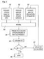
- Fig. 1 is a flow diagram illustrating the basic steps of the method according to the invention. Steps S1 - S3 are performed when a printing press is prepared for a print run. The time sequence, in which these steps are performed is not essential.
- Step S1 consists of measuring the volume carrying capacity of an inking roller that shall be used in a specific colour deck of the printing press. Preferably, this step is performed before the inking roller is mounted in the press.
- Step S2 is a step of measuring the spectral opacity of the print substrate. This step may be performed at any time prior to the print process by inspecting a suitable sample of the print substrate in the printing press or outside the press.
- spectral opacity indicates a set of at least three values that describe the opacity of the print substrate, either in reflectance or in transmission, for at lest three basic colours that span the entire colour space, e. g. the colours RGB or CMY.
- the step S3 is a step of measuring the spectral absorptivity of the liquid ink.
- spectral has the same meaning as in the definition of spectral opacity.
- step S4 the data that have been measured in steps S1 S3 are entered into a mathematical model, typically a software program that is run on a computer and delivers as output a prediction 10 for the colour specifications of the printed product.
- the "printed product” can be thought of as a piece of substrate (of which the spectral opacity has been measured in step S2) with a solid single-colour area printed thereon, i. e. the substrate bears a uniform layer of the ink of which the spectral absorptivity has been measured in step S3.
- the model predicts the thickness of the ink layer on the substrate. Assuming that no ink gets lost in the print process in those image areas where ink is actually deposited on the substrate, the thickness of a layer of liquid ink on the substrate would be given by the measured volume carrying capacity divided by the total surface area of the inking roller. In practise, of course, the thickness of the ink layer on the substrate will shrink because solvent evaporates from the ink. However, if the effect of the solvent on the spectral absorptivity of the ink can be neglected, the "optical thickness" of the layer of dried ink will be equal to the thickness of the hypothetical layer of liquid ink. If there should be an influence of the solvent on the absorptivity, this influence can be included in the model using, for example, the detected viscosity of the liquid ink as a measure for the solvent content.
- the model in step S4 further describes the light reflection, transmission and absorption processes at or in the ink layer on the substrate and at or in the substrate, depending upon whether the print process is a surface printing process or a reverse printing process. These reflection, transmission and absorption processes are calculated for the three basic colours which have been used for defining the spectral opacity of the substrate and the spectral absorptivity of the ink.
- the prediction 10 output by the model will comprise at least three values that describe the expected colour impression of the printed product.
- step S5 the predicted colour impression is compared to certain target specifications that are defined for example by known colour standards such as Pantone or the like.
- the deviation between the expected colour specifications and the target specifications can be quantified by a number ⁇ E which is calculated in step S5.
- step S6 it is decided in step S6 whether or not ⁇ E is larger than 1 (or any other suitable target value). If the answer is yes, this means that the visual colour impression of the printed product must be expected to unacceptably deviate from the target specifications, and the ink composition is adjusted in step S7. On the other hand, if step S6 shows that the expected colour specifications of the printed product are acceptable, the print process will be started in step S8.
- Fig. 2 shows a schematic front view of a so-called mounter 12, i.e. a rack that is normally used for preparing a printing cylinder before the same is mounted in the printing press, but may also be used for performing the step S1 in Fig. 1 .
- mounter 12 i.e. a rack that is normally used for preparing a printing cylinder before the same is mounted in the printing press, but may also be used for performing the step S1 in Fig. 1 .
- the mounter 12 has a base 14 and two releasable bearings 16 in which the opposite ends of an inking roller 18, e. g. an anilox roller for a flexographic printing press, are rotatably supported.
- a drive motor 20 is arranged to be coupled to the inking roller 18 to rotate the same, and an encoder 22 is coupled to the drive motor 20 for detecting the angular position of the inking roller 18.
- the mounter 12 further comprises a rail 24 that is fixedly mounted on the base 14 and extends along the outer surface of the inking roller 18.
- An optical measuring head 26 is guided on the rail 24 and may be driven to move back and forth along the rail 24 so as to scan the surface of the inking roller 18.
- the rail 24 further includes a linear encoder which detects the position of the optical measuring head 26 and signals the same to a control unit 28. When the inking roller 18 is rotated, the encoder 22 counts the angular increments and signals them to the control unit 28, so that the control unit 28 can always determine the angular and axial coordinates of the optical measuring head 26 relative to the inking roller.
- the optical measuring head 26 uses triangulation and/or interferometric techniques for measuring the height of the surface point of the inking roller 18 that is located directly underneath the current position of the optical measuring head.
- triangulation and/or interferometric techniques for measuring the height of the surface point of the inking roller 18 that is located directly underneath the current position of the optical measuring head.
- the mounter may be calibrated to map inherent deviations of the rail 24, which will then be combined in the control unit 28 with the readings from the optical measuring head 26 so as to establish a more accurate topography.
- the exact geometrical shape of the inking roller 18 can be determined with high accuracy in the control unit 28. In particular, it is possible to determine the exact surface area of the inking roller 18.
- the surface of the inking roller 18 is formed with a fine raster of cells 30 that will be filled with ink 32 when, in the printing press, the inking roller passes a doctor blade B.
- the doctor blade will leave ink not only in the cells 30 but also in a thin layer on the surface of the inking roller. The thickness of this layer will depend upon the arrangement and the properties of the doctor blade and also upon the surface properties of the inking roller 18 and the properties of the ink and can thus be determined when these properties are known. Since the optical measuring head 26 scans the surface of the inking roller, it is possible to detect the geometry of the cells 30 and to determine the volume of the cells.
- the inking roller determines the total volume of ink 32 that is carried on the inking roller.
- a certain fraction of this volume will remain on the inking roller.
- This fraction which is again determined by the known surface properties of the inking roller and the printing cylinder and the properties of the ink has to be detracted in order to determine the effective volume carrying capacity of the inking roller.
- the effects of the various properties (material of the inking roller, ink type and condition, etc.) that influence the volume carrying capacity are assessed in advance in a calibration measurement, so that, for a given inking roller, and provided that the ink condition is kept stable, the volume carrying capacity can be calculated as a function of the measured cell volume.
- the ink When the inking roller 18 is operating in the printing press, the ink will be transferred onto the printing parts of the printing cylinder and, finally, onto the surface of the substrate.
- the volume carrying capacity of the inking roller 18 and hence the volume of ink per unit area is known, it is also possible to determine the thickness of a layer that this liquid ink would form on the surface of the print substrate.
- the inking roller 18 includes a memory chip 34, e. g. a RFID chip, and the mounter 12 includes a write head 36 that is controlled by the control unit 28 and may be used for storing the relevant data on the surface area and the volume carrying capacity of the inking roller, so that these data are available in the printing press when the inking roller is mounted therein.
- a memory chip 34 e. g. a RFID chip
- the mounter 12 includes a write head 36 that is controlled by the control unit 28 and may be used for storing the relevant data on the surface area and the volume carrying capacity of the inking roller, so that these data are available in the printing press when the inking roller is mounted therein.
- Another possible method for measuring the cell volume the inking roller 18 may comprise the inspection of the surface of the inking roller with a stereo-graphic video camera system and calculating the dimensions and volumes of the cells 30 from the video data. Yet another method may comprise the steps of applying a metered amount of liquid ink onto the surface of the inking roller 18, spreading that ink on the surface until it has filled all cells 30 in a certain coherent region on the surface of the inking roller, and then measuring the surface area of that region.
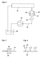
- Fig. 4 shows the essential components of an inking system of a flexographic printing press, for example.
- This inking system comprises an ink fountain 38 that is arranged at the peripheral surface of the inking roller 18 when the latter is mounted in the printing press and serves for filling the cells 30 with liquid ink.
- the inking system further comprises an ink reservoir 40 and a pump 42 for pumping liquid ink from the ink reservoir 40 to the ink fountain 38. Excessive ink that is not transferred to the surface of the ink roller 18 will be returned from the ink fountain 38 to the ink reservoir 40.
- An ink line 44 which connects the pump 42 to the ink fountain 38 includes a viscosimeter 46 for detecting the viscosity of the liquid ink.
- a viscosimeter 46 for detecting the viscosity of the liquid ink.
- the viscosity of the ink must be maintained in a certain range, and when the viscosity is about to leave that range, the viscosity will be adjusted by adding either solvent or ink concentrate.
- the inking system may also include a temperature regulating system for regulating the temperature of the ink in the ink fountain 38. Further, PH control and measurement with the addition of water amide for water based inks may be included.
- the ink line 44 further includes a measuring chamber 48 for measuring the spectral absorptivity of the ink that passes through this chamber.
- a measuring chamber 48 for measuring the spectral absorptivity of the ink that passes through this chamber.
- the spectral absorptivity of the liquid ink in the measuring chamber 48 may be influenced by the solvent content of the ink and, in particular, by an amount of air that is included in the liquid ink, it is preferable that the measurement of the spectral absorptivity is started only after the ink has been pumped through the inking system by means of the pump 42 for a certain time, until the physical and chemical condition of the ink (thixotropy) has reached a stable state that will then be maintained throughout the print process. This assures that the spectral absorptivity that is measured before the print process begins will reflect the actual properties of the ink during the print process.
- Figs. 5 and 6 illustrate different embodiments of the step S2 in Fig. 1 , suitable for a reverse printing process and a surface printing process, respectively.
- Fig. 5 shows a transparent print substrate 54, three standardised light sources 56 that are similar to the light sources 50 in Fig. 4 and are disposed on one side of the substrate 54, and three light detectors 58 similar to the light detectors 52 in Fig. 4 and disposed on the other side of the substrate 54 opposite to the light sources 56.
- This arrangement is suitable for measuring the spectral opacity of the substrate 54 in transmission.
- Fig. 6 shows a substrate 60 and three pairs of light sources 62 and light detectors 64 arranged on the same side of the substrate 60 for measuring the spectral opacity of the substrate in reflection.
- a photospectrometer would be used for detecting the entire absorption spectrum of the substrate and the ink, respectively, over the entire wavelength range of visible light.
- it will generally be sufficient to measure the absorption only at three or more specific wave lengths for giving a sufficiently exact description of the spectral opacities and absorptivities.
- the measurement results obtained with the detectors 52, 58 and 64 may be calibrated on the basis of more precise measurements performed with photo-spectrometers.
- the calibrated measurement results are entered into the model in step S4 in Fig. 1 , they will yield a sufficiently accurate prediction of the colour specifications of the printed product in a suitable colour space such as the LAB space, which prediction may then be compared to the pertinent colour standards.
Landscapes
- Engineering & Computer Science (AREA)
- Quality & Reliability (AREA)
- Inking, Control Or Cleaning Of Printing Machines (AREA)
Priority Applications (6)
| Application Number | Priority Date | Filing Date | Title |
|---|---|---|---|
| EP08020919A EP2193919A1 (fr) | 2008-12-02 | 2008-12-02 | Procédé de définition de couleur dans une presse d'impression rotative |
| BRPI0922755A BRPI0922755A2 (pt) | 2008-12-02 | 2009-11-16 | método de configuração de cores em uma prensa de impressão rotativa. |
| ES09752130T ES2400330T3 (es) | 2008-12-02 | 2009-11-16 | Procedimiento para el ajuste de color en una prensa de impresión rotativa |
| EP09752130A EP2361185B1 (fr) | 2008-12-02 | 2009-11-16 | Procédé de réglage des couleurs dans une presse rotative |
| PCT/EP2009/008148 WO2010063370A1 (fr) | 2008-12-02 | 2009-11-16 | Procédé de réglage des couleurs dans une presse rotative |
| US13/116,454 US20110219975A1 (en) | 2008-12-02 | 2011-05-26 | Method of Colour Setting in a Rotary Printing Press |
Applications Claiming Priority (1)
| Application Number | Priority Date | Filing Date | Title |
|---|---|---|---|
| EP08020919A EP2193919A1 (fr) | 2008-12-02 | 2008-12-02 | Procédé de définition de couleur dans une presse d'impression rotative |
Publications (1)
| Publication Number | Publication Date |
|---|---|
| EP2193919A1 true EP2193919A1 (fr) | 2010-06-09 |
Family
ID=40456728
Family Applications (2)
| Application Number | Title | Priority Date | Filing Date |
|---|---|---|---|
| EP08020919A Withdrawn EP2193919A1 (fr) | 2008-12-02 | 2008-12-02 | Procédé de définition de couleur dans une presse d'impression rotative |
| EP09752130A Active EP2361185B1 (fr) | 2008-12-02 | 2009-11-16 | Procédé de réglage des couleurs dans une presse rotative |
Family Applications After (1)
| Application Number | Title | Priority Date | Filing Date |
|---|---|---|---|
| EP09752130A Active EP2361185B1 (fr) | 2008-12-02 | 2009-11-16 | Procédé de réglage des couleurs dans une presse rotative |
Country Status (5)
| Country | Link |
|---|---|
| US (1) | US20110219975A1 (fr) |
| EP (2) | EP2193919A1 (fr) |
| BR (1) | BRPI0922755A2 (fr) |
| ES (1) | ES2400330T3 (fr) |
| WO (1) | WO2010063370A1 (fr) |
Cited By (2)
| Publication number | Priority date | Publication date | Assignee | Title |
|---|---|---|---|---|
| WO2013081812A1 (fr) * | 2011-11-29 | 2013-06-06 | U.S. Coatings Ip Co. Llc | Processus de contrôle de qualité et de mesure en temps réel pour production de composition liquide |
| EP4063121A1 (fr) * | 2021-03-23 | 2022-09-28 | Ulmex Industrie System GmbH & Co. KG | Procédé et machine de vérification d'un rouleau tramé d'un dispositif d'impression |
Families Citing this family (4)
| Publication number | Priority date | Publication date | Assignee | Title |
|---|---|---|---|---|
| WO2013081903A1 (fr) * | 2011-11-29 | 2013-06-06 | U.S. Coatings Ip Co. Llc | Système de production d'une composition liquide |
| DE102014011151B4 (de) * | 2013-08-23 | 2025-12-24 | Heidelberger Druckmaschinen Ag | Mehrstufiges Regeln und Messen von Deckweiß |
| DK3738773T3 (da) | 2019-05-09 | 2022-10-31 | Heidelberger Druckmasch Ag | Apparat til udmåling af forhøjninger på overfladen af et omdrejningslegeme |
| DE102021125071A1 (de) | 2020-10-22 | 2022-04-28 | Heidelberger Druckmaschinen Aktiengesellschaft | Vorrichtung zum Vermessen von Erhebungen der Oberfläche eines Rotationskörpers |
Citations (3)
| Publication number | Priority date | Publication date | Assignee | Title |
|---|---|---|---|---|
| US4151796A (en) * | 1973-04-02 | 1979-05-01 | Heidelberger Druckmaschinen Aktiengesellschaft | Device for automatically controlling deviations in liquid feed in offset presses |
| EP1916102A1 (fr) | 2006-10-23 | 2008-04-30 | Fischer & Krecke GmbH & Co. KG | Procédé, dispositif de montage et unité de control pour ajuster un cylindre dans une machine à imprimer |
| WO2008049501A2 (fr) * | 2006-10-23 | 2008-05-02 | Fischer & Krecke Gmbh | Presse rotative et procédé pour ajuster un de ses cylindres |
Family Cites Families (2)
| Publication number | Priority date | Publication date | Assignee | Title |
|---|---|---|---|---|
| US4628728A (en) * | 1986-02-21 | 1986-12-16 | Wilson Engraving Company, Inc. | Method for measuring the volumetric capacity of anilox rolls |
| US6575096B1 (en) * | 2001-11-07 | 2003-06-10 | Xerox Corporation | Computer controlled mixing of customer-selected color inks for printing machines |
-
2008
- 2008-12-02 EP EP08020919A patent/EP2193919A1/fr not_active Withdrawn
-
2009
- 2009-11-16 WO PCT/EP2009/008148 patent/WO2010063370A1/fr not_active Ceased
- 2009-11-16 EP EP09752130A patent/EP2361185B1/fr active Active
- 2009-11-16 BR BRPI0922755A patent/BRPI0922755A2/pt not_active IP Right Cessation
- 2009-11-16 ES ES09752130T patent/ES2400330T3/es active Active
-
2011
- 2011-05-26 US US13/116,454 patent/US20110219975A1/en not_active Abandoned
Patent Citations (3)
| Publication number | Priority date | Publication date | Assignee | Title |
|---|---|---|---|---|
| US4151796A (en) * | 1973-04-02 | 1979-05-01 | Heidelberger Druckmaschinen Aktiengesellschaft | Device for automatically controlling deviations in liquid feed in offset presses |
| EP1916102A1 (fr) | 2006-10-23 | 2008-04-30 | Fischer & Krecke GmbH & Co. KG | Procédé, dispositif de montage et unité de control pour ajuster un cylindre dans une machine à imprimer |
| WO2008049501A2 (fr) * | 2006-10-23 | 2008-05-02 | Fischer & Krecke Gmbh | Presse rotative et procédé pour ajuster un de ses cylindres |
Cited By (2)
| Publication number | Priority date | Publication date | Assignee | Title |
|---|---|---|---|---|
| WO2013081812A1 (fr) * | 2011-11-29 | 2013-06-06 | U.S. Coatings Ip Co. Llc | Processus de contrôle de qualité et de mesure en temps réel pour production de composition liquide |
| EP4063121A1 (fr) * | 2021-03-23 | 2022-09-28 | Ulmex Industrie System GmbH & Co. KG | Procédé et machine de vérification d'un rouleau tramé d'un dispositif d'impression |
Also Published As
| Publication number | Publication date |
|---|---|
| BRPI0922755A2 (pt) | 2016-01-05 |
| EP2361185A1 (fr) | 2011-08-31 |
| ES2400330T3 (es) | 2013-04-09 |
| WO2010063370A1 (fr) | 2010-06-10 |
| EP2361185B1 (fr) | 2012-12-19 |
| US20110219975A1 (en) | 2011-09-15 |
Similar Documents
| Publication | Publication Date | Title |
|---|---|---|
| EP2361185B1 (fr) | Procédé de réglage des couleurs dans une presse rotative | |
| JP5204201B2 (ja) | 印刷機 | |
| JP3288628B2 (ja) | 印刷機の湿し液を調節するためのシステム及び方法 | |
| US7515267B2 (en) | Method for determining color and/or density values and printing apparatus configured for the method | |
| US11247450B2 (en) | Method for determining print parameters of a printing machine and test stand | |
| RU2007132920A (ru) | Контроль цвета ротационной печатной машины, использующей цветоизмерения внутри изображения | |
| EP0741032A2 (fr) | Dispositif de mesure de la densité réflective et système de contrÔle pour une machine à imprimer des bandes | |
| JP2007536128A5 (fr) | ||
| EP3526046B1 (fr) | Système et procédé de commande de caractéristiques de couleur d'une image imprimée | |
| US8176847B2 (en) | Method for assessing the plausibility of at least one measured value determined in a printing press | |
| EP3256321B1 (fr) | Système et procédé de surveillance d'utilisation d'encre dans un système d'impression | |
| US7000544B2 (en) | Measurement and regulation of inking in web printing | |
| US20090251504A1 (en) | Systems and methods for wet in-situ calibration using measurement of light transmittance through ink deposited on a substrate | |
| CA2605445C (fr) | Procedes de mesure et de commande de la concentration d'encre et de l'epaisseur de film | |
| TWI785844B (zh) | 印刷系統 | |
| EP1871604B1 (fr) | Procedes de mesure et de commande de la concentration d'encre et de l'epaisseur de film | |
| US20170244869A1 (en) | Color calibration | |
| AU2006247379A1 (en) | Method of, and apparatus for, measuring the quality of a printed image | |
| WO2006046249A1 (fr) | Mesures de densite, de donnees de colorimetrie, et inspection d'une image imprimee a l'aide de detecteurs d'image par contact | |
| WO2020246961A1 (fr) | Dilution en surface pour l'étalonnage de capteurs | |
| JP2002107290A (ja) | 着色液体補充装置及び着色液体補充方法 | |
| US20180024003A1 (en) | Spectrophotometer diagnosis | |
| US20250052618A1 (en) | Method for Spectral Colour Density Measurement in Colour Printing | |
| JPH09300589A (ja) | 巻帯体印刷機用のダイナミック反射密度測定及び制御システム | |
| JP2000246871A (ja) | 色修正装置及び色修正方法 |
Legal Events
| Date | Code | Title | Description |
|---|---|---|---|
| PUAI | Public reference made under article 153(3) epc to a published international application that has entered the european phase |
Free format text: ORIGINAL CODE: 0009012 |
|
| AK | Designated contracting states |
Kind code of ref document: A1 Designated state(s): AT BE BG CH CY CZ DE DK EE ES FI FR GB GR HR HU IE IS IT LI LT LU LV MC MT NL NO PL PT RO SE SI SK TR |
|
| AX | Request for extension of the european patent |
Extension state: AL BA MK RS |
|
| AKY | No designation fees paid | ||
| STAA | Information on the status of an ep patent application or granted ep patent |
Free format text: STATUS: THE APPLICATION IS DEEMED TO BE WITHDRAWN |
|
| 18D | Application deemed to be withdrawn |
Effective date: 20101210 |