EP2194556A1 - Court circuiteur rapide dans un système de distribution électrique - Google Patents
Court circuiteur rapide dans un système de distribution électrique Download PDFInfo
- Publication number
- EP2194556A1 EP2194556A1 EP09177064A EP09177064A EP2194556A1 EP 2194556 A1 EP2194556 A1 EP 2194556A1 EP 09177064 A EP09177064 A EP 09177064A EP 09177064 A EP09177064 A EP 09177064A EP 2194556 A1 EP2194556 A1 EP 2194556A1
- Authority
- EP
- European Patent Office
- Prior art keywords
- electrode
- switch
- receiving recess
- contact point
- moving contact
- Prior art date
- Legal status (The legal status is an assumption and is not a legal conclusion. Google has not performed a legal analysis and makes no representation as to the accuracy of the status listed.)
- Granted
Links
Images



Classifications
-
- H—ELECTRICITY
- H01—ELECTRIC ELEMENTS
- H01H—ELECTRIC SWITCHES; RELAYS; SELECTORS; EMERGENCY PROTECTIVE DEVICES
- H01H33/00—High-tension or heavy-current switches with arc-extinguishing or arc-preventing means
- H01H33/02—Details
- H01H33/28—Power arrangements internal to the switch for operating the driving mechanism
- H01H33/285—Power arrangements internal to the switch for operating the driving mechanism using electro-dynamic repulsion
-
- H—ELECTRICITY
- H01—ELECTRIC ELEMENTS
- H01H—ELECTRIC SWITCHES; RELAYS; SELECTORS; EMERGENCY PROTECTIVE DEVICES
- H01H33/00—High-tension or heavy-current switches with arc-extinguishing or arc-preventing means
- H01H33/02—Details
- H01H33/04—Means for extinguishing or preventing arc between current-carrying parts
- H01H33/20—Means for extinguishing or preventing arc between current-carrying parts using arcing horns
-
- H—ELECTRICITY
- H01—ELECTRIC ELEMENTS
- H01H—ELECTRIC SWITCHES; RELAYS; SELECTORS; EMERGENCY PROTECTIVE DEVICES
- H01H33/00—High-tension or heavy-current switches with arc-extinguishing or arc-preventing means
- H01H33/02—Details
- H01H33/42—Driving mechanisms
-
- H—ELECTRICITY
- H01—ELECTRIC ELEMENTS
- H01H—ELECTRIC SWITCHES; RELAYS; SELECTORS; EMERGENCY PROTECTIVE DEVICES
- H01H79/00—Protective switches in which excess current causes the closing of contacts, e.g. for short-circuiting the apparatus to be protected
Definitions
- the present invention relate to a breaker switch introduced at a high speed within a power distributor and, more particularly, to a high-speed closing switch capable of minimizing damage possibly resulting from an arc accident of a power distributor by inputting high voltage power to a ground at a high speed to detour an accident current immediately when the arc accident occurs at the power distributor.
- a power distributor is a facility that converts power of an especially high voltage into a low voltage and distributing the same to provide power required by a load facility installed at each consumer, and in general, the power distributor includes a switch, a lightning arrester, a transformer, a breaker and various other measurement equipments.
- the breaker provided in the power distributor refers to a device that breaks current when a line is switched on or off or when an accident such as short circuit occurs, and stably protects a power system by switching on or off a line as necessary even in a normal state as well as in an abnormal state such as short circuit.
- the breaker includes a breaking unit insulated with an insulating material within a tank-type container filled with SF 6 , an inert insulating gas having good insulation characteristics and being tasteless, odorless, and nonpoisonous.
- arc-resistance structure used in the power distributor is that a passage for discharging internal pressure is installed to lower pressure increased due to arc or a mechanical strength of a structure is increased to structurally tolerate an increased temperature and pressure according to an arc accident. Or, a dedicated arc breaking device is used to cope with an arc generation.
- a moving unit of the breaking device should move at a high speed to cope with the arc speed.
- a movement speed of the moving unit should be reduced at a final position of the moving unit to reduce an impact and properly control the position.
- the moving unit of the breaking device moves at a high speed, it is difficult to reduce the final speed, and thus, it is difficult to control the final position of the moving unit.
- One aspect of the exemplary embodiments is to provide a high speed closing switch capable of quickly extinguishing an arc generated in a power distributor.
- Another aspect of the present invention is to provide a means for effectively controlling a final position of a moving unit of a switch when the moving unit moves at a high speed.
- This specification provides a high speed closing switch in a power distributor, including: a case forming an external appearance; a first electrode provided within the case and including a through hole; a second electrode having a receiving recess facing the through hole; a moving contact point member having a cylindrical portion received in the through hole so as to be input into (put into, injected into, or inserted into) the receiving recess and a flange portion formed at one end of the cylindrical portion; and a closing coil wound on a base of the case, wherein a damping hole is formed at receiving recess of the second electrode.
- the moving contact point member is input into the receiving recess upon receiving a repulsive force by the closing coil, and an opening coil is wound on one side of the first electrode and provides a repulsive force to the moving contact point member in an opening operation.
- the cylindrical portion of the moving contact point member is formed to be hollow, and a guide member is provided at a base of the case and inserted in the hallow of the cylindrical portion to guide a movement of the cylindrical portion.
- a contact element in contact with the moving contact member is formed on an inner circumferential surface of the through hole of the first electrode and on an inner circumferential surface of the second electrode.
- the contact elements may be a protrusion in a spiral recess formed on the inner circumferential surface of the through hole or a spring mounted in the spiral recess formed on the inner circumferential surface of the through hole.
- the high speed closing switch further includes a pipe with one side of an inner circumferential surface to which the first electrode is combined and the other side combined with the base of the case.
- the damping hole may be formed in a radius direction at an upper portion of the receiving recess of the second electrode.
- One or more damping holes may be formed. If a plurality of damping holes are formed, they may be formed radially in the radius direction at the upper portion of the receiving recess.
- the first electrode is connected to a ground, and the second electrode is connected to a high voltage side.
- the interior of the case is filled with an inert gas and hermetically closed, and the inert gas may be SF 6 , N 2 or air without moisture.
- the first electrode In order to electrically connect the first and second electrodes, the first electrode is put into the receiving recess formed at the second electrode, and at this time, the gas within the receiving recess is discharged through the damping hole formed at the receiving recess.
- the second electrode is put into the receiving recess by a repulsive force between the second electrode and a coil positioned at a lower side of the second electrode.
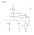
- FIG. 1 is an overall outline view showing a power distributor according to an embodiment of the present invention.
- a power distributor 1 includes an arc-extinguishing system 2, a transformer 3, a main breaker 4, a current sensor 5, a first breaker 6, a second breaker 7, and a high speed closing switch 100.
- a light receiving sensor for receiving light discharged from a generated arc is installed within the power distributor.
- a light signal detected by the light receiving sensor is transmitted to a system body or an overcurrent signal output from a current sensor provided in the power distributor is transmitted to the system body, and a control system can determine whether or an arc accident has occurred based on the conditions. Alternatively, whether an accident has occurred may be determined by simultaneously transmitting two signals.
- a main body of the control system transmits a signal to the main breaker 4.
- the main breaker 4 cannot quickly cope with the arc accident, so the dedicated high speed closing switch reacting at a faster speed is required.
- the dedicated high speed closing switch reacting at a faster speed.
- the dedicated high speed closing switch needs to complete the accident determination and closing operation within 5ms until the arc is grounded.
- FIGs. 2 to 6 illustrate the high speed closing switch including a repeller (Thomson coil) using electronic repelling power according to embodiments of the present invention.
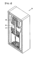
- FIG. 2 is a sectional view of a high speed closing switch of FIG. 1
- FIG. 3 is a detailed sectional view of a first electrode and a moving contact point member of FIG. 2
- FIG. 4A is a detailed sectional view of a second electrode
- FIG. 4B is a plan view of FIG. 4A
- FIG. 4C is a plan view of the second electrode according to another embodiment of the present invention
- FIG. 5 shows an open state of the high speed closing switch according to one embodiment of the present invention
- FIG. 6 shows an input state of the high speed closing switch of FIG. 3 .
- the high speed closing switch 100 includes a first electrode 10 and a second electrode 20 provided at an upper side of the first electrode in a facing manner within a case 200 forming an external appearance of the high speed closing switch 100.
- the first electrode 10 includes a through hole 14 therein, and the second electrode 20 includes a receiving recess 24 facing the through hole 14.
- the high speed closing switch 100 includes a moving contact point member 30 received within the through hole 14 such that it can move up and down.
- a moving contact point member 30 received within the through hole 14 such that it can move up and down.
- an outer circumferential surface of the moving contact point member 30 and an inner circumferential surface of the through hole 14 come in contact with each other, and the outer circumferential surface of the moving contact point member 30 and the inner circumferential surface of the receiving recess 24 also come in contact with each other, according to which the first and second electrodes are electrically connected.
- the moving contact point member 30 includes a cylindrical portion 31 received in the through hole 14 so as to be put into the receiving recess 24 and a flange portion 33 formed at a lower portion of the cylindrical portion 31.
- a closing coil 80 is positioned under the flange portion 33 of the moving contact point member 30 and wound on a base 60 of the case 200.
- various magnetic fields are formed around the closing coil 80, generating an eddy current at the flange portion 33 of the moving contact point member 30.
- the eddy current forms a magnetic field again.
- the magnetic fields formed around the closing coil 80 and the magnetic field formed by the eddy current have the opposite directions, forming strong repulsive power between the closing coil 80 and the flange portion 33.
- the repulsive power instantly generates a strong force pushing up the flange portion 33 from the closing coil 80 wound on the base 60, and accordingly, the moving contact point member 30 instantly moves up at a fast speed so as to be put into the receiving recess 24 of the second electrode 20.
- the operation of inputting the moving contact point member 30 into the receiving recess 24 of the second electrode 20 owing to the strong repulsive power generated between the moving contact point member 30 and the closing coil 80 will be referred to as an 'inputting operation', hereinafter.
- the moving contact point member 30 moves fast due to the early storing repulsive power.
- kinetic energy of the moving contact point member needs to be absorbed, without applying an impact to the case 200 or the like, to make the moving contact point member stop at its proper position accurately.
- a damping hole 90 serving as an orifice is formed at the receiving recess 24 of the second electrode 20.
- the damping hole 90 may be formed to be upwardly vertical at an upper portion of the receiving recess 24 of the second electrode 20.
- the damping hole 90 is formed in a radius direction at an upper portion of the receiving recess 24, and one or a plurality of damping holes may be formed.
- the plurality of damping holes 90 may be radially formed in a radius direction at the upper portion of the receiving recess.
- the size of the damping hole 90 to provide a damping force to the moving contact point member 30 may be determined in consideration of the shape or size of the receiving recess 24 or the moving contact point member 30, but in order to provide a sufficient damping force, the damping hole should have a sufficiently small diameter.
- an inner diameter of a lower portion of the receiving recess 24 of the second electrode 20 is formed to be larger than an outer diameter of the cylindrical portion 31 of the moving contact point member 30, so that when the moving contact point member 30 is input at an early stage, a damping force by a compression gas is not generated, and when an upper portion of the cylindrical portion of the moving contact point member 30 comes in contact with the inner circumferential surface of the receiving recess, the role of the electrical contact of the moving contact point member 30 is completed at the moment, so a mechanical damping force starts to be generated.
- the diameter of the inner circumferential surface of the receiving recess 24 of the second electrode 20 is slightly increased at the lower portion.
- the compressing force of the internal gas acts as a repulsive force to the moving contact point member 30 put into the receiving recess, absorbing kinetic energy of the moving contact point member, to thus generate a damping effect.
- the moving contact point member has a bar shape, so when it is inserted into the second electrode, the sealed gas is leaked along a small discharge passage, whereby the speed of the moving contact point member can be reduced at its final position by the resistance of the fluid.
- One of the first electrode 10 and the second electrode 20 is connected to a ground and another is connected to a high voltage side.
- the moving contact point member electrically connects the first and second electrodes according to the inputting operation, thus connecting the generated arc to the ground.
- the interior of the cylindrical portion 31 is hollow for speed improvement through mass reduction, and a guide member 35 is provided within the cylindrical portion 31 to guide a movement of cylindrical portion 31 when the moving contact point member 30 is moved.
- the guide member 35 has a cylindrical shape and is formed to extend upwardly from the base 60 of the case.
- the guide member 35 is inserted into the internal hollow 32 of the cylindrical portion 31 of the moving contact point member 30 to guide the movement of the cylindrical portion 31.
- the guide member 30 needs to have a sufficient vertical length to guide an upward movement of contact point member in the inputting operation.
- the flange portion 33 of the moving contact point member 30 is positioned below the first electrode 10, and in this case, because the opening coil 70 is wound below the first electrode, current is applied to the opening coil to provide a repulsive force to the flange portion to move down the moving contact point member.
- the principle of generating the repulsive force is the same as in the inputting operation, so its detailed description will be omitted.
- a contact element is formed on the inner circumferential surface of the through hole 14 and on the inner circumferential surface of the receiving recess 24 of the second electrode 20 and comes in contact with the moving contact point member 30 so as to be electrically connected.
- a first recess 11 is formed in a spiral form on the inner circumferential surface of the through hole 14 and a first protrusion 12 is formed between the first recesses 1.
- a second recess 21 is formed in a spiral form on the inner circumferential surface of the receiving recess 24 of the second electrode 20 and a second protrusion 22 is formed between the second recesses 21.
- the outer circumferential surface of the moving contact point member 30 is electrically connected by being in contact with the first protrusion 12 or the second protrusion 22.
- a pipe 40 is provided within the case 200, covering the first electrode 10.
- the pipe 40 has a substantially hollow cylindrical shape.
- the first electrode 10 is combined at an upper portion of the inner circumferential surface of the hollow, and a lower portion of the pipe 40 is combined with the base 60 of the case.
- the pipe 40 covers to protect the first electrode and is made of conductive material to serve as a conductor.
- the interior of the case 200 is filled with an inert gas and sealed against the exterior of the case.
- the inert gas filled at the inner side of the case 200 is SF 6, N 2 , or air without moisture.
- the first electrode 10, the second electrode 20, and the moving contact point member 30 are separately fabricated and combined, but any of the elements may be integrally formed with another element.
- the first electrode 10 and the moving contact point member 30 may be integrally formed and perform inputting operation by using a repulsive force generated between the closing coil and the flange portion.
- the first electrode serves as the moving contact point member.
- FIG. 7 is a sectional view of a high speed closing switch according to another embodiment of the present invention.
- the first recess 11 is formed in a spiral form on the inner circumferential surface of the through hole 14 of the first electrode 10
- a first spring 13 is mounted in the first recess.
- the second recess 21 is formed in a spiral form on the inner circumferential surface of the receiving recess 24 of the second electrode 20.
- the first spring 13 and a second spring 23 are mounted in the first and second recesses, respectively.
- the outer circumferential surface of the moving contact point member 30 is in contact with the first and second springs to thus be electrically connected with the first and second electrodes.
- the power distributor includes the dedicated high speed closing switch to protect the system against an arc.
- the first electrode, the second electrode, the moving contact point member, and the coil for repulsion of the moving contact point member are integrated in the same space.
- the moving contact point member is moved with a very strong repulsive force at an early stage, but its final speed is reduced owing to the shape of moving contact point member and the receiving portion for receiving the moving contact point member at the second electrode to reduce an impact to thus facilitate controlling the final position of the moving contact point member.
- the dedicated high speed closing switch is provided to cope with an arc generated within the power distributor, and an effective damper performance can be implemented at the final position of the moving unit by using a structural shape of the high speed closing switch and the insulation gas within the case.
- the gas present within the case absorbs an impact generated in the high speed inputting operation, when the high speed closing switch is suddenly stopped from its operation, noise and impact can be reduced. Therefore, in the high speed closing switch according to the present invention, the final position of the moving unit can be smoothly controlled.
Landscapes
- Arc-Extinguishing Devices That Are Switches (AREA)
- Driving Mechanisms And Operating Circuits Of Arc-Extinguishing High-Tension Switches (AREA)
- Details Of Television Scanning (AREA)
Applications Claiming Priority (1)
| Application Number | Priority Date | Filing Date | Title |
|---|---|---|---|
| KR1020080122121A KR101013709B1 (ko) | 2008-12-03 | 2008-12-03 | 수배전반의 고속 투입 스위치 |
Publications (2)
| Publication Number | Publication Date |
|---|---|
| EP2194556A1 true EP2194556A1 (fr) | 2010-06-09 |
| EP2194556B1 EP2194556B1 (fr) | 2014-09-24 |
Family
ID=41693441
Family Applications (1)
| Application Number | Title | Priority Date | Filing Date |
|---|---|---|---|
| EP09177064.4A Active EP2194556B1 (fr) | 2008-12-03 | 2009-11-25 | Court circuiteur rapide dans un système de distribution électrique |
Country Status (6)
| Country | Link |
|---|---|
| US (1) | US8258419B2 (fr) |
| EP (1) | EP2194556B1 (fr) |
| JP (1) | JP4950270B2 (fr) |
| KR (1) | KR101013709B1 (fr) |
| CN (1) | CN101752108B (fr) |
| ES (1) | ES2525128T3 (fr) |
Cited By (3)
| Publication number | Priority date | Publication date | Assignee | Title |
|---|---|---|---|---|
| WO2013022572A1 (fr) * | 2011-08-05 | 2013-02-14 | Eaton Corporation | Dispositif de protection anti-arcs isolé |
| EP3070727A1 (fr) * | 2015-03-20 | 2016-09-21 | Siemens Aktiengesellschaft | Dispositif sectionneur de déconnexion ou connexion électrique haute-tension |
| EP3241225A4 (fr) * | 2014-12-30 | 2018-08-01 | Hyosung Corporation | Dispositif de commutation rapide |
Families Citing this family (22)
| Publication number | Priority date | Publication date | Assignee | Title |
|---|---|---|---|---|
| KR20110079233A (ko) * | 2009-12-31 | 2011-07-07 | 엘에스산전 주식회사 | 기밀형 전자개폐기 |
| KR101212212B1 (ko) | 2011-05-25 | 2012-12-13 | 엘에스산전 주식회사 | 고속스위치의 가동전극 정지기구 |
| EP2546848B1 (fr) * | 2011-07-14 | 2014-09-03 | ABB Technology AG | Commutateur rapide avec bobine Thomson non circulaire |
| JP5153971B1 (ja) * | 2012-04-10 | 2013-02-27 | 三菱電機株式会社 | 電力用開閉装置 |
| KR101696955B1 (ko) * | 2012-06-29 | 2017-01-16 | 엘에스산전 주식회사 | 전자 개폐기 |
| KR101410780B1 (ko) | 2013-03-14 | 2014-06-23 | 엘에스산전 주식회사 | 전력회로 개폐기용 트립 액추에이터 |
| KR101491488B1 (ko) * | 2013-10-10 | 2015-02-09 | 현대중공업 주식회사 | 고속투입스위치 |
| KR101822323B1 (ko) | 2014-05-21 | 2018-01-25 | 미쓰비시덴키 가부시키가이샤 | 아크 엘리미네이터를 구비한 차단기 및 그것을 적용한 수배전 설비 |
| KR101704807B1 (ko) * | 2014-12-31 | 2017-02-08 | 주식회사 효성 | 차단기용 전자반발 조작기 |
| US9842717B2 (en) | 2015-05-29 | 2017-12-12 | Lsis Co., Ltd. | High speed closing switch |
| EP3439013A1 (fr) | 2017-08-04 | 2019-02-06 | ABB Schweiz AG | Armature pour actionneur électromagnétique, actionneur électromagnétique, dispositif de commutation et procédé de fabrication d'une armature |
| JP6907967B2 (ja) * | 2018-02-23 | 2021-07-21 | オムロン株式会社 | アーク放電検知装置 |
| JP6513304B1 (ja) | 2018-02-27 | 2019-05-15 | 三菱電機株式会社 | 電磁アクチュエータ、開閉器およびスイッチギア |
| DE102018209479A1 (de) | 2018-06-13 | 2019-12-19 | Knorr-Bremse Systeme für Nutzfahrzeuge GmbH | Bedienungssicheres Parkventil |
| WO2020217292A1 (fr) * | 2019-04-23 | 2020-10-29 | 三菱電機株式会社 | Appareillage de commutation et groupe d'appareillage de commutation |
| KR102095408B1 (ko) * | 2019-09-04 | 2020-04-01 | 주식회사 스마트파워 | 아크 제거장치 |
| US10923304B1 (en) * | 2019-09-13 | 2021-02-16 | Eaton Intelligent Power Limited | Vacuum circuit breaker operating mechanism |
| WO2021210058A1 (fr) * | 2020-04-14 | 2021-10-21 | 三菱電機株式会社 | Appareillage de commutation et convertisseur de puissance |
| EP4095876B1 (fr) * | 2021-05-25 | 2023-12-27 | ABB S.p.A. | Dispositif de rupture |
| EP4199022B1 (fr) | 2021-12-17 | 2024-06-26 | Abb Schweiz Ag | Dispositif d'extinction d'arc triphasé avec deux pistons |
| KR102505794B1 (ko) * | 2022-03-25 | 2023-03-06 | 주식회사 프로텍타코리아 | 아크해소 수배전반 |
| JP2025098512A (ja) * | 2023-12-20 | 2025-07-02 | 株式会社日立製作所 | ガス絶縁開閉装置の可動部移動量計測方法、ガス絶縁開閉装置の動作劣化診断方法、及び、ガス絶縁開閉装置の保守方法 |
Citations (8)
| Publication number | Priority date | Publication date | Assignee | Title |
|---|---|---|---|---|
| US2951188A (en) * | 1956-01-10 | 1960-08-30 | Ite Circuit Breaker Ltd | High speed contacting device |
| GB1449015A (en) * | 1973-02-26 | 1976-09-08 | Skoda Np | Contact assembly for an electric switch |
| FR2357048A1 (fr) * | 1976-06-28 | 1978-01-27 | Merlin Gerin | Interrupteur electrique dote d'un propulseur electrodynamique et d'un amortisseur pneumatique |
| FR2493031A1 (fr) * | 1980-10-27 | 1982-04-30 | Merlin Gerin | Enclencheur rapide a contact coulissant |
| US4435627A (en) * | 1980-07-18 | 1984-03-06 | Bbc Brown, Boveri & Company, Limited | High tension circuit breaker |
| WO1996019816A1 (fr) * | 1994-12-22 | 1996-06-27 | Asea Brown Boveri Ab | Dispositif electrique de commutation |
| EP2073229A1 (fr) * | 2007-12-18 | 2009-06-24 | Schneider Electric Industries SAS | Court-circuiteur pyrotechnique à contacts électrique auto-serrant et ensemble de protection contre les arcs internes comportant un tel court-circuiteur |
| US20090166168A1 (en) * | 2007-12-28 | 2009-07-02 | Mitsubishi Electric Corporation | Grounding switch |
Family Cites Families (15)
| Publication number | Priority date | Publication date | Assignee | Title |
|---|---|---|---|---|
| DE2855326A1 (de) | 1978-12-21 | 1980-07-17 | Wabco Fahrzeugbremsen Gmbh | Schaltungsanordnung zur verbesserung der fahrstabilitaet im bremsfalle bei fahrzeugen mit blockiergeschuetzten fahrzeugbremsanlagen |
| DE3132305C2 (de) * | 1981-08-17 | 1986-10-16 | Licentia Patent-Verwaltungs-Gmbh, 6000 Frankfurt | Autopneumatischer Druckgasschalter |
| JPS60130522A (ja) | 1983-12-19 | 1985-07-12 | Masatoshi Nakano | 魚類の皮膚黄色化現象除去剤 |
| FR2622737B1 (fr) | 1987-11-04 | 1995-04-14 | Merlin Gerin | Disjoncteur electrique a auto-expansion a volume de chambre d'extinction variable |
| SE9101831L (sv) * | 1991-06-14 | 1993-03-10 | Asea Brown Boveri | Saekerhetsbrytare med lutningsindikering |
| JPH0864084A (ja) * | 1994-08-19 | 1996-03-08 | Toshiba Corp | パッファ形ガス遮断器 |
| US6538347B1 (en) * | 1995-05-15 | 2003-03-25 | Mcgraw-Edison Company | Electrical switchgear with synchronous control system and actuator |
| US5892194A (en) * | 1996-03-26 | 1999-04-06 | Matsushita Electric Works, Ltd. | Sealed contact device with contact gap adjustment capability |
| FR2748598B1 (fr) * | 1996-05-13 | 1998-06-05 | Gec Alsthom T & D Sa | Disjoncteur a haute tension a auto-soufflage |
| JP2000251588A (ja) | 1999-02-25 | 2000-09-14 | Toshiba Corp | 液圧操作装置 |
| JP2000331576A (ja) | 1999-05-24 | 2000-11-30 | Mitsubishi Electric Corp | 真空開閉装置 |
| JP2002056752A (ja) | 2000-08-11 | 2002-02-22 | Toshiba Corp | ガス遮断器 |
| JP2003109476A (ja) | 2001-09-27 | 2003-04-11 | Toshiba Corp | ガス遮断器 |
| US7078643B2 (en) * | 2003-12-15 | 2006-07-18 | Rostron Joseph R | Capacitor switch with internal retracting impedance contactor |
| JP4114665B2 (ja) | 2004-08-10 | 2008-07-09 | 株式会社日立エレクトリックシステムズ | 配電用開閉装置 |
-
2008
- 2008-12-03 KR KR1020080122121A patent/KR101013709B1/ko active Active
-
2009
- 2009-11-24 US US12/624,896 patent/US8258419B2/en active Active
- 2009-11-25 ES ES09177064.4T patent/ES2525128T3/es active Active
- 2009-11-25 EP EP09177064.4A patent/EP2194556B1/fr active Active
- 2009-12-01 JP JP2009273708A patent/JP4950270B2/ja active Active
- 2009-12-03 CN CN2009102119419A patent/CN101752108B/zh active Active
Patent Citations (8)
| Publication number | Priority date | Publication date | Assignee | Title |
|---|---|---|---|---|
| US2951188A (en) * | 1956-01-10 | 1960-08-30 | Ite Circuit Breaker Ltd | High speed contacting device |
| GB1449015A (en) * | 1973-02-26 | 1976-09-08 | Skoda Np | Contact assembly for an electric switch |
| FR2357048A1 (fr) * | 1976-06-28 | 1978-01-27 | Merlin Gerin | Interrupteur electrique dote d'un propulseur electrodynamique et d'un amortisseur pneumatique |
| US4435627A (en) * | 1980-07-18 | 1984-03-06 | Bbc Brown, Boveri & Company, Limited | High tension circuit breaker |
| FR2493031A1 (fr) * | 1980-10-27 | 1982-04-30 | Merlin Gerin | Enclencheur rapide a contact coulissant |
| WO1996019816A1 (fr) * | 1994-12-22 | 1996-06-27 | Asea Brown Boveri Ab | Dispositif electrique de commutation |
| EP2073229A1 (fr) * | 2007-12-18 | 2009-06-24 | Schneider Electric Industries SAS | Court-circuiteur pyrotechnique à contacts électrique auto-serrant et ensemble de protection contre les arcs internes comportant un tel court-circuiteur |
| US20090166168A1 (en) * | 2007-12-28 | 2009-07-02 | Mitsubishi Electric Corporation | Grounding switch |
Cited By (5)
| Publication number | Priority date | Publication date | Assignee | Title |
|---|---|---|---|---|
| WO2013022572A1 (fr) * | 2011-08-05 | 2013-02-14 | Eaton Corporation | Dispositif de protection anti-arcs isolé |
| US8492672B2 (en) | 2011-08-05 | 2013-07-23 | Eaton Corporation | Insulated arc flash arrester |
| EP3241225A4 (fr) * | 2014-12-30 | 2018-08-01 | Hyosung Corporation | Dispositif de commutation rapide |
| EP3070727A1 (fr) * | 2015-03-20 | 2016-09-21 | Siemens Aktiengesellschaft | Dispositif sectionneur de déconnexion ou connexion électrique haute-tension |
| WO2016150637A1 (fr) * | 2015-03-20 | 2016-09-29 | Siemens Aktiengesellschaft | Dispositif sectionneur de déconnexion ou connexion électrique haute-tension |
Also Published As
| Publication number | Publication date |
|---|---|
| JP2010135323A (ja) | 2010-06-17 |
| ES2525128T3 (es) | 2014-12-17 |
| JP4950270B2 (ja) | 2012-06-13 |
| EP2194556B1 (fr) | 2014-09-24 |
| US8258419B2 (en) | 2012-09-04 |
| US20100133080A1 (en) | 2010-06-03 |
| KR101013709B1 (ko) | 2011-02-10 |
| CN101752108A (zh) | 2010-06-23 |
| KR20100063556A (ko) | 2010-06-11 |
| CN101752108B (zh) | 2013-01-02 |
Similar Documents
| Publication | Publication Date | Title |
|---|---|---|
| US8258419B2 (en) | High-speed closing switch in power distributor | |
| JP5516568B2 (ja) | パッファ形ガス遮断器 | |
| JP5153255B2 (ja) | 接地開閉装置 | |
| JP6219105B2 (ja) | 開閉器 | |
| US9336974B2 (en) | Gas circuit breaker | |
| CN103748650A (zh) | 充气式空气断路器 | |
| US9842717B2 (en) | High speed closing switch | |
| US9679708B2 (en) | Circuit interrupters with masses in contact spring assemblies | |
| EP3059752B1 (fr) | Ampoule à vide | |
| EP2822017B1 (fr) | Disjoncteur à gaz haute tension | |
| KR20160021663A (ko) | 진공차단기의 진공인터럽터 | |
| KR20120097856A (ko) | 가스 차단기의 소호부 | |
| KR101935376B1 (ko) | 고전압 개폐기 | |
| KR101779721B1 (ko) | 고속 투입 스위치 | |
| AU2022388491B2 (en) | Vacuum interrupter anti-bounce dampener | |
| JP2013134864A (ja) | 投入抵抗器付きパッファ形ガス遮断器 | |
| CN202260228U (zh) | 带有气体的绝缘的高压开关设备 | |
| JP2017120756A (ja) | 開閉装置 | |
| CN117153591A (zh) | 用于开关设备的开关 | |
| JP2016225023A (ja) | ガス遮断器 | |
| KR20130076480A (ko) | 개폐기용 진공 차단기 |
Legal Events
| Date | Code | Title | Description |
|---|---|---|---|
| PUAI | Public reference made under article 153(3) epc to a published international application that has entered the european phase |
Free format text: ORIGINAL CODE: 0009012 |
|
| 17P | Request for examination filed |
Effective date: 20091125 |
|
| AK | Designated contracting states |
Kind code of ref document: A1 Designated state(s): AT BE BG CH CY CZ DE DK EE ES FI FR GB GR HR HU IE IS IT LI LT LU LV MC MK MT NL NO PL PT RO SE SI SK SM TR |
|
| AX | Request for extension of the european patent |
Extension state: AL BA RS |
|
| 17Q | First examination report despatched |
Effective date: 20100817 |
|
| GRAP | Despatch of communication of intention to grant a patent |
Free format text: ORIGINAL CODE: EPIDOSNIGR1 |
|
| INTG | Intention to grant announced |
Effective date: 20140414 |
|
| GRAS | Grant fee paid |
Free format text: ORIGINAL CODE: EPIDOSNIGR3 |
|
| GRAA | (expected) grant |
Free format text: ORIGINAL CODE: 0009210 |
|
| AK | Designated contracting states |
Kind code of ref document: B1 Designated state(s): AT BE BG CH CY CZ DE DK EE ES FI FR GB GR HR HU IE IS IT LI LT LU LV MC MK MT NL NO PL PT RO SE SI SK SM TR |
|
| REG | Reference to a national code |
Ref country code: GB Ref legal event code: FG4D |
|
| REG | Reference to a national code |
Ref country code: CH Ref legal event code: EP |
|
| REG | Reference to a national code |
Ref country code: AT Ref legal event code: REF Ref document number: 688936 Country of ref document: AT Kind code of ref document: T Effective date: 20141015 |
|
| REG | Reference to a national code |
Ref country code: IE Ref legal event code: FG4D |
|
| REG | Reference to a national code |
Ref country code: DE Ref legal event code: R096 Ref document number: 602009026803 Country of ref document: DE Effective date: 20141106 |
|
| REG | Reference to a national code |
Ref country code: ES Ref legal event code: FG2A Ref document number: 2525128 Country of ref document: ES Kind code of ref document: T3 Effective date: 20141217 |
|
| PG25 | Lapsed in a contracting state [announced via postgrant information from national office to epo] |
Ref country code: NO Free format text: LAPSE BECAUSE OF FAILURE TO SUBMIT A TRANSLATION OF THE DESCRIPTION OR TO PAY THE FEE WITHIN THE PRESCRIBED TIME-LIMIT Effective date: 20141224 Ref country code: FI Free format text: LAPSE BECAUSE OF FAILURE TO SUBMIT A TRANSLATION OF THE DESCRIPTION OR TO PAY THE FEE WITHIN THE PRESCRIBED TIME-LIMIT Effective date: 20140924 Ref country code: LT Free format text: LAPSE BECAUSE OF FAILURE TO SUBMIT A TRANSLATION OF THE DESCRIPTION OR TO PAY THE FEE WITHIN THE PRESCRIBED TIME-LIMIT Effective date: 20140924 Ref country code: GR Free format text: LAPSE BECAUSE OF FAILURE TO SUBMIT A TRANSLATION OF THE DESCRIPTION OR TO PAY THE FEE WITHIN THE PRESCRIBED TIME-LIMIT Effective date: 20141225 Ref country code: SE Free format text: LAPSE BECAUSE OF FAILURE TO SUBMIT A TRANSLATION OF THE DESCRIPTION OR TO PAY THE FEE WITHIN THE PRESCRIBED TIME-LIMIT Effective date: 20140924 |
|
| REG | Reference to a national code |
Ref country code: LT Ref legal event code: MG4D Ref country code: NL Ref legal event code: VDEP Effective date: 20140924 |
|
| PG25 | Lapsed in a contracting state [announced via postgrant information from national office to epo] |
Ref country code: HR Free format text: LAPSE BECAUSE OF FAILURE TO SUBMIT A TRANSLATION OF THE DESCRIPTION OR TO PAY THE FEE WITHIN THE PRESCRIBED TIME-LIMIT Effective date: 20140924 Ref country code: LV Free format text: LAPSE BECAUSE OF FAILURE TO SUBMIT A TRANSLATION OF THE DESCRIPTION OR TO PAY THE FEE WITHIN THE PRESCRIBED TIME-LIMIT Effective date: 20140924 Ref country code: CY Free format text: LAPSE BECAUSE OF FAILURE TO SUBMIT A TRANSLATION OF THE DESCRIPTION OR TO PAY THE FEE WITHIN THE PRESCRIBED TIME-LIMIT Effective date: 20140924 |
|
| REG | Reference to a national code |
Ref country code: AT Ref legal event code: MK05 Ref document number: 688936 Country of ref document: AT Kind code of ref document: T Effective date: 20140924 |
|
| PG25 | Lapsed in a contracting state [announced via postgrant information from national office to epo] |
Ref country code: NL Free format text: LAPSE BECAUSE OF FAILURE TO SUBMIT A TRANSLATION OF THE DESCRIPTION OR TO PAY THE FEE WITHIN THE PRESCRIBED TIME-LIMIT Effective date: 20140924 |
|
| PG25 | Lapsed in a contracting state [announced via postgrant information from national office to epo] |
Ref country code: IS Free format text: LAPSE BECAUSE OF FAILURE TO SUBMIT A TRANSLATION OF THE DESCRIPTION OR TO PAY THE FEE WITHIN THE PRESCRIBED TIME-LIMIT Effective date: 20150124 Ref country code: CZ Free format text: LAPSE BECAUSE OF FAILURE TO SUBMIT A TRANSLATION OF THE DESCRIPTION OR TO PAY THE FEE WITHIN THE PRESCRIBED TIME-LIMIT Effective date: 20140924 Ref country code: SK Free format text: LAPSE BECAUSE OF FAILURE TO SUBMIT A TRANSLATION OF THE DESCRIPTION OR TO PAY THE FEE WITHIN THE PRESCRIBED TIME-LIMIT Effective date: 20140924 Ref country code: EE Free format text: LAPSE BECAUSE OF FAILURE TO SUBMIT A TRANSLATION OF THE DESCRIPTION OR TO PAY THE FEE WITHIN THE PRESCRIBED TIME-LIMIT Effective date: 20140924 Ref country code: PT Free format text: LAPSE BECAUSE OF FAILURE TO SUBMIT A TRANSLATION OF THE DESCRIPTION OR TO PAY THE FEE WITHIN THE PRESCRIBED TIME-LIMIT Effective date: 20150126 Ref country code: RO Free format text: LAPSE BECAUSE OF FAILURE TO SUBMIT A TRANSLATION OF THE DESCRIPTION OR TO PAY THE FEE WITHIN THE PRESCRIBED TIME-LIMIT Effective date: 20140924 |
|
| PG25 | Lapsed in a contracting state [announced via postgrant information from national office to epo] |
Ref country code: PL Free format text: LAPSE BECAUSE OF FAILURE TO SUBMIT A TRANSLATION OF THE DESCRIPTION OR TO PAY THE FEE WITHIN THE PRESCRIBED TIME-LIMIT Effective date: 20140924 Ref country code: AT Free format text: LAPSE BECAUSE OF FAILURE TO SUBMIT A TRANSLATION OF THE DESCRIPTION OR TO PAY THE FEE WITHIN THE PRESCRIBED TIME-LIMIT Effective date: 20140924 |
|
| REG | Reference to a national code |
Ref country code: DE Ref legal event code: R097 Ref document number: 602009026803 Country of ref document: DE |
|
| PG25 | Lapsed in a contracting state [announced via postgrant information from national office to epo] |
Ref country code: MC Free format text: LAPSE BECAUSE OF FAILURE TO SUBMIT A TRANSLATION OF THE DESCRIPTION OR TO PAY THE FEE WITHIN THE PRESCRIBED TIME-LIMIT Effective date: 20140924 Ref country code: BE Free format text: LAPSE BECAUSE OF NON-PAYMENT OF DUE FEES Effective date: 20141130 Ref country code: LU Free format text: LAPSE BECAUSE OF FAILURE TO SUBMIT A TRANSLATION OF THE DESCRIPTION OR TO PAY THE FEE WITHIN THE PRESCRIBED TIME-LIMIT Effective date: 20141125 |
|
| REG | Reference to a national code |
Ref country code: CH Ref legal event code: PL |
|
| PG25 | Lapsed in a contracting state [announced via postgrant information from national office to epo] |
Ref country code: LI Free format text: LAPSE BECAUSE OF NON-PAYMENT OF DUE FEES Effective date: 20141130 Ref country code: DK Free format text: LAPSE BECAUSE OF FAILURE TO SUBMIT A TRANSLATION OF THE DESCRIPTION OR TO PAY THE FEE WITHIN THE PRESCRIBED TIME-LIMIT Effective date: 20140924 Ref country code: CH Free format text: LAPSE BECAUSE OF NON-PAYMENT OF DUE FEES Effective date: 20141130 |
|
| PLBE | No opposition filed within time limit |
Free format text: ORIGINAL CODE: 0009261 |
|
| STAA | Information on the status of an ep patent application or granted ep patent |
Free format text: STATUS: NO OPPOSITION FILED WITHIN TIME LIMIT |
|
| REG | Reference to a national code |
Ref country code: IE Ref legal event code: MM4A |
|
| 26N | No opposition filed |
Effective date: 20150625 |
|
| REG | Reference to a national code |
Ref country code: FR Ref legal event code: PLFP Year of fee payment: 7 |
|
| PG25 | Lapsed in a contracting state [announced via postgrant information from national office to epo] |
Ref country code: IE Free format text: LAPSE BECAUSE OF NON-PAYMENT OF DUE FEES Effective date: 20141125 |
|
| PG25 | Lapsed in a contracting state [announced via postgrant information from national office to epo] |
Ref country code: SI Free format text: LAPSE BECAUSE OF FAILURE TO SUBMIT A TRANSLATION OF THE DESCRIPTION OR TO PAY THE FEE WITHIN THE PRESCRIBED TIME-LIMIT Effective date: 20140924 |
|
| PG25 | Lapsed in a contracting state [announced via postgrant information from national office to epo] |
Ref country code: SM Free format text: LAPSE BECAUSE OF FAILURE TO SUBMIT A TRANSLATION OF THE DESCRIPTION OR TO PAY THE FEE WITHIN THE PRESCRIBED TIME-LIMIT Effective date: 20140924 |
|
| PG25 | Lapsed in a contracting state [announced via postgrant information from national office to epo] |
Ref country code: BG Free format text: LAPSE BECAUSE OF FAILURE TO SUBMIT A TRANSLATION OF THE DESCRIPTION OR TO PAY THE FEE WITHIN THE PRESCRIBED TIME-LIMIT Effective date: 20140924 |
|
| PG25 | Lapsed in a contracting state [announced via postgrant information from national office to epo] |
Ref country code: HU Free format text: LAPSE BECAUSE OF FAILURE TO SUBMIT A TRANSLATION OF THE DESCRIPTION OR TO PAY THE FEE WITHIN THE PRESCRIBED TIME-LIMIT; INVALID AB INITIO Effective date: 20091125 Ref country code: TR Free format text: LAPSE BECAUSE OF FAILURE TO SUBMIT A TRANSLATION OF THE DESCRIPTION OR TO PAY THE FEE WITHIN THE PRESCRIBED TIME-LIMIT Effective date: 20140924 Ref country code: MT Free format text: LAPSE BECAUSE OF FAILURE TO SUBMIT A TRANSLATION OF THE DESCRIPTION OR TO PAY THE FEE WITHIN THE PRESCRIBED TIME-LIMIT Effective date: 20140924 |
|
| REG | Reference to a national code |
Ref country code: FR Ref legal event code: PLFP Year of fee payment: 8 |
|
| REG | Reference to a national code |
Ref country code: FR Ref legal event code: PLFP Year of fee payment: 9 |
|
| PG25 | Lapsed in a contracting state [announced via postgrant information from national office to epo] |
Ref country code: MK Free format text: LAPSE BECAUSE OF FAILURE TO SUBMIT A TRANSLATION OF THE DESCRIPTION OR TO PAY THE FEE WITHIN THE PRESCRIBED TIME-LIMIT Effective date: 20140924 |
|
| REG | Reference to a national code |
Ref country code: FR Ref legal event code: PLFP Year of fee payment: 10 |
|
| P01 | Opt-out of the competence of the unified patent court (upc) registered |
Effective date: 20230625 |
|
| PGFP | Annual fee paid to national office [announced via postgrant information from national office to epo] |
Ref country code: IT Payment date: 20250909 Year of fee payment: 17 |
|
| PGFP | Annual fee paid to national office [announced via postgrant information from national office to epo] |
Ref country code: GB Payment date: 20250909 Year of fee payment: 17 |
|
| PGFP | Annual fee paid to national office [announced via postgrant information from national office to epo] |
Ref country code: FR Payment date: 20250909 Year of fee payment: 17 |
|
| PGFP | Annual fee paid to national office [announced via postgrant information from national office to epo] |
Ref country code: DE Payment date: 20250908 Year of fee payment: 17 |
|
| PGFP | Annual fee paid to national office [announced via postgrant information from national office to epo] |
Ref country code: ES Payment date: 20251215 Year of fee payment: 17 |