EP2196761A1 - Vorrichtung zur Fernauslösung von Sprengladungen - Google Patents
Vorrichtung zur Fernauslösung von Sprengladungen Download PDFInfo
- Publication number
- EP2196761A1 EP2196761A1 EP09178307A EP09178307A EP2196761A1 EP 2196761 A1 EP2196761 A1 EP 2196761A1 EP 09178307 A EP09178307 A EP 09178307A EP 09178307 A EP09178307 A EP 09178307A EP 2196761 A1 EP2196761 A1 EP 2196761A1
- Authority
- EP
- European Patent Office
- Prior art keywords
- housing
- heating zones
- vehicle
- support structure
- infrared
- Prior art date
- Legal status (The legal status is an assumption and is not a legal conclusion. Google has not performed a legal analysis and makes no representation as to the accuracy of the status listed.)
- Granted
Links
Images
Classifications
-
- F—MECHANICAL ENGINEERING; LIGHTING; HEATING; WEAPONS; BLASTING
- F41—WEAPONS
- F41H—ARMOUR; ARMOURED TURRETS; ARMOURED OR ARMED VEHICLES; MEANS OF ATTACK OR DEFENCE, e.g. CAMOUFLAGE, IN GENERAL
- F41H11/00—Defence installations; Defence devices
- F41H11/12—Means for clearing land minefields; Systems specially adapted for detection of landmines
-
- F—MECHANICAL ENGINEERING; LIGHTING; HEATING; WEAPONS; BLASTING
- F42—AMMUNITION; BLASTING
- F42D—BLASTING
- F42D5/00—Safety arrangements
- F42D5/04—Rendering explosive charges harmless, e.g. destroying ammunition; Rendering detonation of explosive charges harmless
Definitions
- the present invention relates to a device for remotely triggering explosive charges, such as in particular mines or improvised explosive devices, infrared trigger sensor.
- a mine-detection device with an infrared trigger sensor which consists of an unmanned driving vehicle with a thermal source and thus functioning as a decoy for the infrared sensor of the mine, the latter exploding when the unmanned vehicle passes by triggering its sensor lured by the thermal source. Then, vehicles can continue their progression safely at least with regard to this type of explosive charges.
- the object of the present invention is to remedy these drawbacks and relates to a device for triggering explosive charges of the type described above, the design of which makes it possible to act as a decoy on all the explosive charges activated by a thermal sensor. while being of a technically simple realization.
- the device of the invention can cover precise and different temperature ranges to decoy the infrared sensors of the charges integrating in particular signal processing on the temperature of the detected target (vehicle). For example, a "low” temperature for the thermal signature of the vehicle engine and a “high” temperature for the thermal signature of the engine exhaust line.
- this type of explosive charges is triggered by the heat radiation of the heating zones of the device which decoys the load sensors.
- the electric generator is housed in the housing, it is protected from any projections or splinters due to the triggering of the explosive charges, so that the heating zones remain active.
- the device is a simple structure hitched to the front of the motorized pusher vehicle, so that its design is technically simple and less expensive than a self-driving unmanned vehicle.
- the device comprises a protective grid externally fixed to the wall of said housing, in front of the heating zone at high temperature.
- said heating zones with adjustable temperature are generated by electrical resistance networks reported on said wall of the housing. Note the simplicity of realization of the heating zones of the thermal generator.
- heating zones are preferably connected to a control / monitoring device ensuring their operation and their thermal regulation and monitoring.
- said housing has a substantially parallelepipedal flattened shape whose two large opposite walls form said radiant heating zones and are arranged in substantially vertical planes oriented respectively on either side of the direction of movement of said structure. of support.
- each large wall of said housing has both said separate heating zones.
- said support structure is in the form of a beam on the front end of which is mounted said thermal box and which is adapted to be connected at its rear end to points attachment of said vehicle.
- the device is mounted cantilever, well away from the pusher vehicle, protecting it from the explosion of loads.
- the mounting of said housing on the front end of the structure is preferably of the hinged suspension type about a substantially horizontal axis of articulation in the direction of movement of said structure.
- the front of said support structure is bent upwards to form approximately an inverted C in which said housing is inscribed.
- said support structure when not in use, can be raised relative to the vehicle and locked in the raised position.
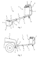
- the figure 1 is a perspective view of an exemplary embodiment of a device for triggering explosive charges according to the invention.
- the figure 2 is a plan view of the device of the invention mounted at the front of a vehicle.
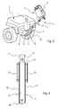
- the figure 3 represents the device coupled to the vehicle in the raised position.
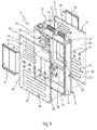
- the figure 4 is a front view of the front of the device housing.
- the figure 5 is an exploded perspective view of the housing of the device comprising said heat source.
- the device 1 is intended to trigger explosive charges not shown, such as mines and / or improvised explosive devices, equipped with infrared trigger sensor.
- the device 1 comprises an infrared thermal signal electric generator 2 acting as a thermal source for decoying the infrared sensors of the explosive charges so that they are triggered, a protective case 3 including the electric generator 2 and a supporting structure 4 of the housing 3, intended to be mounted at the front of a motorized vehicle 5 military type.
- the supporting structure 4 is in the form of a beam 6 which consists of tubular parts 7 rigidly assembled and which is arranged in the vertical longitudinal plane of symmetry P ( figure 3 ) of the vehicle, so as to move the electric generator 2 from the front 8 of the vehicle 5, to ensure the release of the charges before the passage of the vehicle (including its hot springs as the engine and the exhaust line) in front of them.
- to mount the supporting structure 4 of the device 1 on the vehicle 5 is advantageously used towing strengths provided in the front 8 of military vehicles and which are defined by two parallel towing rings 9, as seen on the Figures 1 to 3 , a stirrup 10 U-shaped whose base 11 is fixedly attached to the vehicle body.
- the U-shaped stirrup is disposed symmetrically with respect to the vertical longitudinal plane of symmetry of the vehicle 5 and the then enlarged proximal end 12 of the beam is introduced between the parallel rings 9 of the stirrup 10 and connected to those ci by an axis 14 passing through the horizontal aligned eyelets 15 of the towing rings.
- the distal end 16 of the beam is curved upwards to form an inverted C in which the housing 3 fits, so as to put it, with its thermal source, at a certain height of the ground (corresponding substantially the engine and the vehicle exhaust system) and to protect it from possible shocks with obstacles during the mission.
- the casing 3 is preferably suspended at the distal end 16 of the beam 6 by a quick hinge link 17 incorporating a substantially horizontal axis of articulation 18, contained in the vertical longitudinal plane of symmetry of the vehicle 5, so that the housing 3 has a lateral degree of freedom, being able to oscillate about said axis 18.
- the device 1 thus protrudes longitudinally with respect to the front 8 of the vehicle 5 and is maintained, in this substantially horizontal position, by any means not shown (stop, ...) to prevent its rotation, provided at its link (axis 14) with the vehicle.
- a wheel 19 is further provided under the distal end 16 of the beam to provide a ground support of the device 1 and its displacement.
- the trigger device 1 of the invention is liftable relative to the vehicle 5 and lockable in the raised position as shown, when it is not in use.
- a not shown rotation locking mechanism of the hinge axis relative to the towing rings can be provided or other means of retaining the device in the raised position.
- the housing 3 of the electric generator 2 has a rather flattened parallelepipedal shape, defined by two walls or opposite main plates or large walls 20 and 21, parallel to the longitudinal vertical plane of symmetry of the vehicle and connected to one another by four opposite side walls two by two respectively front, rear 22, 23 and upper, lower 24, 25.
- One of these side walls, in this case the upper wall 24, externally carries the corresponding hinges 17 of the axis of articulation 18 connecting the suspended housing 3 to the curved distal end 16 of the beam 6.
- the two main walls 20, 21 of the housing are made of metal and act as radiant heating zones generated by the electric generator 2 by means of electrical resistance networks 28 fixed to the inner face 29. walls 20 and 21.
- These resistors are connected to the power supply of the vehicle 5 by a cable not shown, passing through the beam 6 of the supporting structure 4, via a control / control device 30 housed in the housing and which ensures inter alia the operation of the resistors, the regulation of their temperature and the triggering of alarm in case of malfunction.
- the main walls 20, 21 of the housing constitute the radiating surfaces of the decoy, so as to emit infrared radiation, both in the direction of the front left side than towards the front right side of the vehicle, thus triggering the sensors explosive charges well before the passage of the vehicle.
- each main wall 20, 21 has two distinct heating zones 26, 27 having operating temperatures or ranges of temperatures. different. So, in the example shown on the figure 5 a first low temperature zone 26, representative of the temperature emitted by the engine of a vehicle, and a second high temperature zone 27, representative of the temperature emitted by its exhaust line, can be provided to deceive the sensors. infrared.
- the high temperature zone 27 is located in the upper part 32 of each wall 20, 21, while the low temperature zone 26 is in the lower part 33 of the walls.
- each wall In order to limit the thermal conduction between the high and low temperature zones 26, 27 of each wall, provision is made in each of them for openings 34 at best separating said radiating zones from the housings.
- the openings 34 shown are circular but they could be oblong or have any other shape.
- each main wall is protected by an external grid 35 fixedly attached, removably, to the housing.
- Each low temperature zone 26 could, if necessary, also be covered with a protective grid.
- the thermal regulation provided by the device 30 can be ensured, in this example, by three temperature sensors (not shown), two for the respective high and low temperature zones and one measuring the ambient temperature.
- three temperature sensors not shown
- an alarm indicating this error deviation is triggered and goes back to the driver of the vehicle.
- the latter can control the device of the invention 1 from its driving position by means of a suitable control box not shown in the figures.
- the housing 3 containing the heat source 2 is furthermore sealed and reinforced, in particular by internal partitions 36, in particular to withstand the blast effect of ammunition activated by other peripheral triggering means to the infrared lure of the invention and to the different splinters generated.
Landscapes
- Engineering & Computer Science (AREA)
- General Engineering & Computer Science (AREA)
- Aiming, Guidance, Guns With A Light Source, Armor, Camouflage, And Targets (AREA)
- Geophysics And Detection Of Objects (AREA)
- Optical Radar Systems And Details Thereof (AREA)
- Traffic Control Systems (AREA)
- Lining Or Joining Of Plastics Or The Like (AREA)
- Burglar Alarm Systems (AREA)
Applications Claiming Priority (1)
| Application Number | Priority Date | Filing Date | Title |
|---|---|---|---|
| FR0806924A FR2939503B1 (fr) | 2008-12-10 | 2008-12-10 | Dispositif pour declencher a distance des charges explosives |
Publications (2)
| Publication Number | Publication Date |
|---|---|
| EP2196761A1 true EP2196761A1 (de) | 2010-06-16 |
| EP2196761B1 EP2196761B1 (de) | 2012-01-04 |
Family
ID=40908935
Family Applications (1)
| Application Number | Title | Priority Date | Filing Date |
|---|---|---|---|
| EP09178307A Active EP2196761B1 (de) | 2008-12-10 | 2009-12-08 | Vorrichtung zur Fernauslösung von Sprengladungen |
Country Status (8)
| Country | Link |
|---|---|
| US (1) | US8541717B2 (de) |
| EP (1) | EP2196761B1 (de) |
| AT (1) | ATE540282T1 (de) |
| CA (1) | CA2744879C (de) |
| ES (1) | ES2380183T3 (de) |
| FR (1) | FR2939503B1 (de) |
| WO (1) | WO2010067000A1 (de) |
| ZA (1) | ZA201104321B (de) |
Cited By (1)
| Publication number | Priority date | Publication date | Assignee | Title |
|---|---|---|---|---|
| CN109631708A (zh) * | 2018-12-25 | 2019-04-16 | 江西理工大学 | 一种中小铝土矿块爆破用防护装置 |
Families Citing this family (1)
| Publication number | Priority date | Publication date | Assignee | Title |
|---|---|---|---|---|
| US11221196B2 (en) * | 2015-03-30 | 2022-01-11 | Director General, Defence Research & Development Organisation (Drdo) | Vehicle and method for detecting and neutralizing an incendiary object |
Citations (4)
| Publication number | Priority date | Publication date | Assignee | Title |
|---|---|---|---|---|
| EP1054230A1 (de) * | 1999-05-18 | 2000-11-22 | Giat Industries | Täuscheinrichtung zum Irreführen einer Landmine |
| JP2007183065A (ja) * | 2006-01-10 | 2007-07-19 | Ihi Aerospace Co Ltd | オフルート地雷処理装置 |
| GB2434349A (en) * | 2006-01-24 | 2007-07-25 | Jason Philip Lewis | Remotely operated reconnaissance vehicle |
| US20080134869A1 (en) * | 2005-12-22 | 2008-06-12 | Stuart Owen Goldman | Forced premature detonation of improvised explosive devices via radiated electromagnetic energy |
Family Cites Families (5)
| Publication number | Priority date | Publication date | Assignee | Title |
|---|---|---|---|---|
| US5668342A (en) * | 1995-12-07 | 1997-09-16 | Discher; Stephen R. W. | Apparatus and method for detection and neutralization of concealed explosives |
| AU2003295857A1 (en) * | 2002-11-21 | 2004-06-18 | Ada Technologies, Inc. | Strobe desorption method for high boiling point materials |
| US7752953B2 (en) * | 2003-03-12 | 2010-07-13 | Lsp Technologies, Inc. | Method and system for neutralization of buried mines |
| US7130624B1 (en) * | 2003-11-12 | 2006-10-31 | Jackson Richard H | System and method for destabilizing improvised explosive devices |
| US7512511B1 (en) * | 2006-03-30 | 2009-03-31 | The Boeing Company | Improvised explosive device countermeasures |
-
2008
- 2008-12-10 FR FR0806924A patent/FR2939503B1/fr active Active
-
2009
- 2009-12-08 ES ES09178307T patent/ES2380183T3/es active Active
- 2009-12-08 EP EP09178307A patent/EP2196761B1/de active Active
- 2009-12-08 AT AT09178307T patent/ATE540282T1/de active
- 2009-12-08 US US13/133,361 patent/US8541717B2/en active Active
- 2009-12-08 WO PCT/FR2009/052436 patent/WO2010067000A1/fr not_active Ceased
- 2009-12-08 CA CA2744879A patent/CA2744879C/fr active Active
-
2011
- 2011-06-09 ZA ZA2011/04321A patent/ZA201104321B/en unknown
Patent Citations (4)
| Publication number | Priority date | Publication date | Assignee | Title |
|---|---|---|---|---|
| EP1054230A1 (de) * | 1999-05-18 | 2000-11-22 | Giat Industries | Täuscheinrichtung zum Irreführen einer Landmine |
| US20080134869A1 (en) * | 2005-12-22 | 2008-06-12 | Stuart Owen Goldman | Forced premature detonation of improvised explosive devices via radiated electromagnetic energy |
| JP2007183065A (ja) * | 2006-01-10 | 2007-07-19 | Ihi Aerospace Co Ltd | オフルート地雷処理装置 |
| GB2434349A (en) * | 2006-01-24 | 2007-07-25 | Jason Philip Lewis | Remotely operated reconnaissance vehicle |
Cited By (1)
| Publication number | Priority date | Publication date | Assignee | Title |
|---|---|---|---|---|
| CN109631708A (zh) * | 2018-12-25 | 2019-04-16 | 江西理工大学 | 一种中小铝土矿块爆破用防护装置 |
Also Published As
| Publication number | Publication date |
|---|---|
| ES2380183T3 (es) | 2012-05-09 |
| ZA201104321B (en) | 2012-02-29 |
| FR2939503B1 (fr) | 2013-01-11 |
| CA2744879C (fr) | 2016-06-07 |
| FR2939503A1 (fr) | 2010-06-11 |
| US20110233188A1 (en) | 2011-09-29 |
| ATE540282T1 (de) | 2012-01-15 |
| WO2010067000A1 (fr) | 2010-06-17 |
| CA2744879A1 (fr) | 2010-06-17 |
| EP2196761B1 (de) | 2012-01-04 |
| US8541717B2 (en) | 2013-09-24 |
Similar Documents
| Publication | Publication Date | Title |
|---|---|---|
| EP2196762B1 (de) | Rollendes Material zum Auslösen von Sprengladungen und motorisierte Einheit zum Sichern von Straßen, Pisten und Ähnlichem | |
| EP2196761B1 (de) | Vorrichtung zur Fernauslösung von Sprengladungen | |
| FR2730805A1 (fr) | Dispositif de protection contre une projectile en approche | |
| FR2754049A1 (fr) | Dispositif de lancement d'engins autopropulses | |
| EP1448947B1 (de) | Beobachtungs- und kampfsystem | |
| EP1054370B1 (de) | Vorrichtung zum Schutz eines Gebietes gegen Eindringen | |
| EP1275927A2 (de) | Vorrichtung zur Befestigung eines Beobachtungsmittels | |
| EP1054230B1 (de) | Täuscheinrichtung zum Irreführen einer Landmine | |
| FR2559069A1 (fr) | Dispositif et procede de securite contre les incendies et les explosions pour le stockage des matieres combustibles ou explosives | |
| WO2016151250A1 (fr) | Dispositif de détection d'incendies de foret énergétiquement autonome et procédé de détection d'incendies de foret mettant en œuvre un tel dispositif | |
| FR2907206A1 (fr) | Blindage actif avec capteurs infrarouges | |
| FR2882433A1 (fr) | Dispositif de detection de temperature muni d'un moyen d'avertissement de danger, et casque equipe d'un tel dispositif | |
| FR2939504A1 (fr) | Materiel roulant pour declencher des charges explosives | |
| EP1688327B1 (de) | Sperrvorrichtung für eine Lenkspindel | |
| FR2612288A1 (fr) | Munition de survol a charge basculante | |
| EP1750972B1 (de) | Verbesserte scheinwerfer für kraftfahrzeuge | |
| FR3063684A1 (fr) | Dispositif de protection pour batterie de propulsion comprenant un cadre ouvert | |
| FR3044802A1 (fr) | Dispositif de detection d'incendies de foret energetiquement autonome et procede de detection d'incendies de foret mettant en œuvre un tel dispositif | |
| FR2924211A1 (fr) | Dispositif d'autoprotection d'un vehicule | |
| FR3145405A1 (fr) | Dispositif de gestion climatique pour serre de culture | |
| WO2026082667A1 (fr) | Ensemble de détection d'échauffement d'une batterie de traction d'un véhicule automobile électrique et procédé de détection d'échauffement mis en œuvre par ledit ensemble | |
| BR102022018759A2 (pt) | Sistema de proteção tático | |
| EP1793196A1 (de) | Minenräumgerät | |
| FR3129886A1 (fr) | Dispositif lumineux d’un véhicule automobile | |
| FR2903179A1 (fr) | Dispositif de protection d'un plancher d'un vehicule terrestre portant un organe externe |
Legal Events
| Date | Code | Title | Description |
|---|---|---|---|
| PUAI | Public reference made under article 153(3) epc to a published international application that has entered the european phase |
Free format text: ORIGINAL CODE: 0009012 |
|
| AK | Designated contracting states |
Kind code of ref document: A1 Designated state(s): AT BE BG CH CY CZ DE DK EE ES FI FR GB GR HR HU IE IS IT LI LT LU LV MC MK MT NL NO PL PT RO SE SI SK SM TR |
|
| AX | Request for extension of the european patent |
Extension state: AL BA RS |
|
| 17P | Request for examination filed |
Effective date: 20100915 |
|
| GRAP | Despatch of communication of intention to grant a patent |
Free format text: ORIGINAL CODE: EPIDOSNIGR1 |
|
| RIC1 | Information provided on ipc code assigned before grant |
Ipc: F42D 5/04 20060101ALI20110706BHEP Ipc: F41H 11/12 20110101AFI20110706BHEP |
|
| GRAS | Grant fee paid |
Free format text: ORIGINAL CODE: EPIDOSNIGR3 |
|
| GRAA | (expected) grant |
Free format text: ORIGINAL CODE: 0009210 |
|
| AK | Designated contracting states |
Kind code of ref document: B1 Designated state(s): AT BE BG CH CY CZ DE DK EE ES FI FR GB GR HR HU IE IS IT LI LT LU LV MC MK MT NL NO PL PT RO SE SI SK SM TR |
|
| REG | Reference to a national code |
Ref country code: GB Ref legal event code: FG4D Free format text: NOT ENGLISH |
|
| REG | Reference to a national code |
Ref country code: CH Ref legal event code: EP |
|
| REG | Reference to a national code |
Ref country code: AT Ref legal event code: REF Ref document number: 540282 Country of ref document: AT Kind code of ref document: T Effective date: 20120115 |
|
| REG | Reference to a national code |
Ref country code: IE Ref legal event code: FG4D |
|
| REG | Reference to a national code |
Ref country code: DE Ref legal event code: R096 Ref document number: 602009004499 Country of ref document: DE Effective date: 20120308 |
|
| REG | Reference to a national code |
Ref country code: SE Ref legal event code: TRGR |
|
| REG | Reference to a national code |
Ref country code: NL Ref legal event code: VDEP Effective date: 20120104 |
|
| REG | Reference to a national code |
Ref country code: ES Ref legal event code: FG2A Ref document number: 2380183 Country of ref document: ES Kind code of ref document: T3 Effective date: 20120509 |
|
| PG25 | Lapsed in a contracting state [announced via postgrant information from national office to epo] |
Ref country code: SI Free format text: LAPSE BECAUSE OF FAILURE TO SUBMIT A TRANSLATION OF THE DESCRIPTION OR TO PAY THE FEE WITHIN THE PRESCRIBED TIME-LIMIT Effective date: 20120104 |
|
| LTIE | Lt: invalidation of european patent or patent extension |
Effective date: 20120104 |
|
| PG25 | Lapsed in a contracting state [announced via postgrant information from national office to epo] |
Ref country code: IS Free format text: LAPSE BECAUSE OF FAILURE TO SUBMIT A TRANSLATION OF THE DESCRIPTION OR TO PAY THE FEE WITHIN THE PRESCRIBED TIME-LIMIT Effective date: 20120504 Ref country code: BG Free format text: LAPSE BECAUSE OF FAILURE TO SUBMIT A TRANSLATION OF THE DESCRIPTION OR TO PAY THE FEE WITHIN THE PRESCRIBED TIME-LIMIT Effective date: 20120404 Ref country code: NO Free format text: LAPSE BECAUSE OF FAILURE TO SUBMIT A TRANSLATION OF THE DESCRIPTION OR TO PAY THE FEE WITHIN THE PRESCRIBED TIME-LIMIT Effective date: 20120404 Ref country code: HR Free format text: LAPSE BECAUSE OF FAILURE TO SUBMIT A TRANSLATION OF THE DESCRIPTION OR TO PAY THE FEE WITHIN THE PRESCRIBED TIME-LIMIT Effective date: 20120104 Ref country code: LT Free format text: LAPSE BECAUSE OF FAILURE TO SUBMIT A TRANSLATION OF THE DESCRIPTION OR TO PAY THE FEE WITHIN THE PRESCRIBED TIME-LIMIT Effective date: 20120104 Ref country code: NL Free format text: LAPSE BECAUSE OF FAILURE TO SUBMIT A TRANSLATION OF THE DESCRIPTION OR TO PAY THE FEE WITHIN THE PRESCRIBED TIME-LIMIT Effective date: 20120104 |
|
| REG | Reference to a national code |
Ref country code: IE Ref legal event code: FD4D |
|
| PG25 | Lapsed in a contracting state [announced via postgrant information from national office to epo] |
Ref country code: PL Free format text: LAPSE BECAUSE OF FAILURE TO SUBMIT A TRANSLATION OF THE DESCRIPTION OR TO PAY THE FEE WITHIN THE PRESCRIBED TIME-LIMIT Effective date: 20120104 Ref country code: PT Free format text: LAPSE BECAUSE OF FAILURE TO SUBMIT A TRANSLATION OF THE DESCRIPTION OR TO PAY THE FEE WITHIN THE PRESCRIBED TIME-LIMIT Effective date: 20120504 Ref country code: FI Free format text: LAPSE BECAUSE OF FAILURE TO SUBMIT A TRANSLATION OF THE DESCRIPTION OR TO PAY THE FEE WITHIN THE PRESCRIBED TIME-LIMIT Effective date: 20120104 Ref country code: LV Free format text: LAPSE BECAUSE OF FAILURE TO SUBMIT A TRANSLATION OF THE DESCRIPTION OR TO PAY THE FEE WITHIN THE PRESCRIBED TIME-LIMIT Effective date: 20120104 Ref country code: GR Free format text: LAPSE BECAUSE OF FAILURE TO SUBMIT A TRANSLATION OF THE DESCRIPTION OR TO PAY THE FEE WITHIN THE PRESCRIBED TIME-LIMIT Effective date: 20120405 |
|
| REG | Reference to a national code |
Ref country code: AT Ref legal event code: MK05 Ref document number: 540282 Country of ref document: AT Kind code of ref document: T Effective date: 20120104 |
|
| PG25 | Lapsed in a contracting state [announced via postgrant information from national office to epo] |
Ref country code: CY Free format text: LAPSE BECAUSE OF FAILURE TO SUBMIT A TRANSLATION OF THE DESCRIPTION OR TO PAY THE FEE WITHIN THE PRESCRIBED TIME-LIMIT Effective date: 20120104 |
|
| PG25 | Lapsed in a contracting state [announced via postgrant information from national office to epo] |
Ref country code: DK Free format text: LAPSE BECAUSE OF FAILURE TO SUBMIT A TRANSLATION OF THE DESCRIPTION OR TO PAY THE FEE WITHIN THE PRESCRIBED TIME-LIMIT Effective date: 20120104 Ref country code: EE Free format text: LAPSE BECAUSE OF FAILURE TO SUBMIT A TRANSLATION OF THE DESCRIPTION OR TO PAY THE FEE WITHIN THE PRESCRIBED TIME-LIMIT Effective date: 20120104 Ref country code: IE Free format text: LAPSE BECAUSE OF FAILURE TO SUBMIT A TRANSLATION OF THE DESCRIPTION OR TO PAY THE FEE WITHIN THE PRESCRIBED TIME-LIMIT Effective date: 20120104 Ref country code: RO Free format text: LAPSE BECAUSE OF FAILURE TO SUBMIT A TRANSLATION OF THE DESCRIPTION OR TO PAY THE FEE WITHIN THE PRESCRIBED TIME-LIMIT Effective date: 20120104 Ref country code: CZ Free format text: LAPSE BECAUSE OF FAILURE TO SUBMIT A TRANSLATION OF THE DESCRIPTION OR TO PAY THE FEE WITHIN THE PRESCRIBED TIME-LIMIT Effective date: 20120104 |
|
| PLBE | No opposition filed within time limit |
Free format text: ORIGINAL CODE: 0009261 |
|
| STAA | Information on the status of an ep patent application or granted ep patent |
Free format text: STATUS: NO OPPOSITION FILED WITHIN TIME LIMIT |
|
| PG25 | Lapsed in a contracting state [announced via postgrant information from national office to epo] |
Ref country code: SK Free format text: LAPSE BECAUSE OF FAILURE TO SUBMIT A TRANSLATION OF THE DESCRIPTION OR TO PAY THE FEE WITHIN THE PRESCRIBED TIME-LIMIT Effective date: 20120104 |
|
| 26N | No opposition filed |
Effective date: 20121005 |
|
| PG25 | Lapsed in a contracting state [announced via postgrant information from national office to epo] |
Ref country code: AT Free format text: LAPSE BECAUSE OF FAILURE TO SUBMIT A TRANSLATION OF THE DESCRIPTION OR TO PAY THE FEE WITHIN THE PRESCRIBED TIME-LIMIT Effective date: 20120104 |
|
| REG | Reference to a national code |
Ref country code: DE Ref legal event code: R097 Ref document number: 602009004499 Country of ref document: DE Effective date: 20121005 |
|
| BERE | Be: lapsed |
Owner name: MBDA FRANCE Effective date: 20121231 |
|
| PG25 | Lapsed in a contracting state [announced via postgrant information from national office to epo] |
Ref country code: MC Free format text: LAPSE BECAUSE OF NON-PAYMENT OF DUE FEES Effective date: 20121231 |
|
| REG | Reference to a national code |
Ref country code: FR Ref legal event code: ST Effective date: 20130830 |
|
| PG25 | Lapsed in a contracting state [announced via postgrant information from national office to epo] |
Ref country code: BE Free format text: LAPSE BECAUSE OF NON-PAYMENT OF DUE FEES Effective date: 20121231 |
|
| PG25 | Lapsed in a contracting state [announced via postgrant information from national office to epo] |
Ref country code: MT Free format text: LAPSE BECAUSE OF FAILURE TO SUBMIT A TRANSLATION OF THE DESCRIPTION OR TO PAY THE FEE WITHIN THE PRESCRIBED TIME-LIMIT Effective date: 20120104 Ref country code: FR Free format text: LAPSE BECAUSE OF NON-PAYMENT OF DUE FEES Effective date: 20130102 |
|
| PG25 | Lapsed in a contracting state [announced via postgrant information from national office to epo] |
Ref country code: TR Free format text: LAPSE BECAUSE OF FAILURE TO SUBMIT A TRANSLATION OF THE DESCRIPTION OR TO PAY THE FEE WITHIN THE PRESCRIBED TIME-LIMIT Effective date: 20120104 |
|
| PG25 | Lapsed in a contracting state [announced via postgrant information from national office to epo] |
Ref country code: LU Free format text: LAPSE BECAUSE OF NON-PAYMENT OF DUE FEES Effective date: 20121208 Ref country code: SM Free format text: LAPSE BECAUSE OF FAILURE TO SUBMIT A TRANSLATION OF THE DESCRIPTION OR TO PAY THE FEE WITHIN THE PRESCRIBED TIME-LIMIT Effective date: 20120104 |
|
| PG25 | Lapsed in a contracting state [announced via postgrant information from national office to epo] |
Ref country code: HU Free format text: LAPSE BECAUSE OF FAILURE TO SUBMIT A TRANSLATION OF THE DESCRIPTION OR TO PAY THE FEE WITHIN THE PRESCRIBED TIME-LIMIT Effective date: 20091208 |
|
| REG | Reference to a national code |
Ref country code: CH Ref legal event code: PL |
|
| PG25 | Lapsed in a contracting state [announced via postgrant information from national office to epo] |
Ref country code: LI Free format text: LAPSE BECAUSE OF NON-PAYMENT OF DUE FEES Effective date: 20131231 Ref country code: CH Free format text: LAPSE BECAUSE OF NON-PAYMENT OF DUE FEES Effective date: 20131231 |
|
| PG25 | Lapsed in a contracting state [announced via postgrant information from national office to epo] |
Ref country code: MK Free format text: LAPSE BECAUSE OF FAILURE TO SUBMIT A TRANSLATION OF THE DESCRIPTION OR TO PAY THE FEE WITHIN THE PRESCRIBED TIME-LIMIT Effective date: 20120104 |
|
| P01 | Opt-out of the competence of the unified patent court (upc) registered |
Effective date: 20230630 |
|
| REG | Reference to a national code |
Ref country code: GB Ref legal event code: 732E Free format text: REGISTERED BETWEEN 20241205 AND 20241211 |
|
| REG | Reference to a national code |
Ref country code: DE Ref legal event code: R081 Ref document number: 602009004499 Country of ref document: DE Owner name: SERA INGENIERIE, FR Free format text: FORMER OWNER: MBDA FRANCE, PARIS, FR |
|
| PGFP | Annual fee paid to national office [announced via postgrant information from national office to epo] |
Ref country code: GB Payment date: 20251223 Year of fee payment: 17 |
|
| PGFP | Annual fee paid to national office [announced via postgrant information from national office to epo] |
Ref country code: IT Payment date: 20251209 Year of fee payment: 17 |
|
| PGFP | Annual fee paid to national office [announced via postgrant information from national office to epo] |
Ref country code: SE Payment date: 20251218 Year of fee payment: 17 |
|
| PGFP | Annual fee paid to national office [announced via postgrant information from national office to epo] |
Ref country code: ES Payment date: 20260112 Year of fee payment: 17 |
|
| PGFP | Annual fee paid to national office [announced via postgrant information from national office to epo] |
Ref country code: DE Payment date: 20251231 Year of fee payment: 17 |