EP1054230A1 - Täuscheinrichtung zum Irreführen einer Landmine - Google Patents
Täuscheinrichtung zum Irreführen einer Landmine Download PDFInfo
- Publication number
- EP1054230A1 EP1054230A1 EP00401178A EP00401178A EP1054230A1 EP 1054230 A1 EP1054230 A1 EP 1054230A1 EP 00401178 A EP00401178 A EP 00401178A EP 00401178 A EP00401178 A EP 00401178A EP 1054230 A1 EP1054230 A1 EP 1054230A1
- Authority
- EP
- European Patent Office
- Prior art keywords
- flag
- luring device
- heating element
- temperature
- luring
- Prior art date
- Legal status (The legal status is an assumption and is not a legal conclusion. Google has not performed a legal analysis and makes no representation as to the accuracy of the status listed.)
- Granted
Links
- 230000005855 radiation Effects 0.000 claims abstract description 4
- 238000002329 infrared spectrum Methods 0.000 claims abstract description 3
- 238000010438 heat treatment Methods 0.000 claims description 37
- 239000000463 material Substances 0.000 claims description 10
- 238000001465 metallisation Methods 0.000 claims description 3
- 230000001276 controlling effect Effects 0.000 claims 1
- 230000001105 regulatory effect Effects 0.000 claims 1
- 230000005540 biological transmission Effects 0.000 abstract description 2
- 238000000034 method Methods 0.000 abstract 1
- 239000004020 conductor Substances 0.000 description 11
- 230000006378 damage Effects 0.000 description 4
- 230000002093 peripheral effect Effects 0.000 description 3
- 238000004804 winding Methods 0.000 description 2
- XAGFODPZIPBFFR-UHFFFAOYSA-N aluminium Chemical compound [Al] XAGFODPZIPBFFR-UHFFFAOYSA-N 0.000 description 1
- 229910052782 aluminium Inorganic materials 0.000 description 1
- 230000003321 amplification Effects 0.000 description 1
- 230000033228 biological regulation Effects 0.000 description 1
- 229920001940 conductive polymer Polymers 0.000 description 1
- 238000012790 confirmation Methods 0.000 description 1
- 230000007423 decrease Effects 0.000 description 1
- 238000001514 detection method Methods 0.000 description 1
- 238000005265 energy consumption Methods 0.000 description 1
- 238000004880 explosion Methods 0.000 description 1
- 238000010304 firing Methods 0.000 description 1
- 239000007789 gas Substances 0.000 description 1
- 239000012212 insulator Substances 0.000 description 1
- 238000005259 measurement Methods 0.000 description 1
- 238000012544 monitoring process Methods 0.000 description 1
- 238000003199 nucleic acid amplification method Methods 0.000 description 1
- 230000001681 protective effect Effects 0.000 description 1
- 238000007650 screen-printing Methods 0.000 description 1
- 238000004088 simulation Methods 0.000 description 1
Images


Classifications
-
- F—MECHANICAL ENGINEERING; LIGHTING; HEATING; WEAPONS; BLASTING
- F41—WEAPONS
- F41H—ARMOUR; ARMOURED TURRETS; ARMOURED OR ARMED VEHICLES; MEANS OF ATTACK OR DEFENCE, e.g. CAMOUFLAGE, IN GENERAL
- F41H3/00—Camouflage, i.e. means or methods for concealment or disguise
-
- F—MECHANICAL ENGINEERING; LIGHTING; HEATING; WEAPONS; BLASTING
- F41—WEAPONS
- F41H—ARMOUR; ARMOURED TURRETS; ARMOURED OR ARMED VEHICLES; MEANS OF ATTACK OR DEFENCE, e.g. CAMOUFLAGE, IN GENERAL
- F41H11/00—Defence installations; Defence devices
- F41H11/02—Anti-aircraft or anti-guided missile or anti-torpedo defence installations or systems
-
- F—MECHANICAL ENGINEERING; LIGHTING; HEATING; WEAPONS; BLASTING
- F41—WEAPONS
- F41H—ARMOUR; ARMOURED TURRETS; ARMOURED OR ARMED VEHICLES; MEANS OF ATTACK OR DEFENCE, e.g. CAMOUFLAGE, IN GENERAL
- F41H11/00—Defence installations; Defence devices
- F41H11/12—Means for clearing land minefields; Systems specially adapted for detection of landmines
- F41H11/16—Self-propelled mine-clearing vehicles; Mine-clearing devices attachable to vehicles
- F41H11/32—Decoy or sacrificial vehicles; Decoy or sacrificial devices attachable to vehicles
-
- F—MECHANICAL ENGINEERING; LIGHTING; HEATING; WEAPONS; BLASTING
- F41—WEAPONS
- F41H—ARMOUR; ARMOURED TURRETS; ARMOURED OR ARMED VEHICLES; MEANS OF ATTACK OR DEFENCE, e.g. CAMOUFLAGE, IN GENERAL
- F41H5/00—Armour; Armour plates
- F41H5/02—Plate construction
- F41H5/023—Armour plate, or auxiliary armour plate mounted at a distance of the main armour plate, having cavities at its outer impact surface, or holes, for deflecting the projectile
- F41H5/026—Slat armour; Nets
-
- F—MECHANICAL ENGINEERING; LIGHTING; HEATING; WEAPONS; BLASTING
- F41—WEAPONS
- F41J—TARGETS; TARGET RANGES; BULLET CATCHERS
- F41J2/00—Reflecting targets, e.g. radar-reflector targets; Active targets transmitting electromagnetic or acoustic waves
- F41J2/02—Active targets transmitting infrared radiation
Definitions
- the technical field of the invention is that of decoy devices, especially edge mines road.
- Such decoy devices are placed at the head of a column of vehicles or tanks. They aim to triggering mines remotely from vehicles of combat in order to clear a route.
- This system consists of a small remote-controlled vehicle which carries in the front part rods in the shape of needles which are sunk into the ground to initiate sensor mines pressure.
- This vehicle also includes means for decoy allowing to generate an infrared signature close to that of a tank.
- Such an arrangement allows trigger roadside mines (mines with horizontal action) which generally have infrared sensors.
- the infrared decoy means described include a device which directs the exhaust gases from the engine of the vehicle to upper and / or lateral areas of the vehicle to heat them up.
- the decoy device allows to ensure the safe triggering of on-board mines road while avoiding destruction of the vehicle deception.
- the subject of the invention is therefore a decoy device, in particular a roadside mine, characterized in that that it comprises at least one flag fixed on a support, flag comprising at least one part ensuring transmission of radiation in the infrared spectrum.
- the flag may consist of at least one flexible panel carrying at minus one heating element.
- the heating element (s) may be connected to a temperature control means.
- At least one temperature sensor may be placed at the near the heating element and be connected by means steering.
- the heating element may include at least one element flexible conductor fixed at the level of a first part of the panel and following a curve whose shape ensures when heating element operation producing a thermal gradient between the first part and a second part of the panel.
- the curve formed by the flexible conductive element may be a damped sinusoid.
- the flag can be produced in one flexible rollable material and the support may include minus a reel.
- the flag may consist of at least three flexible strips, at least one of these bands carrying a heating element.
- the temperature of each heating element carried by a band can be slaved to a different value for each strip.
- the heating element of each strip may include at least least one conductive element extending longitudinally between an upper edge and a lower edge of the strip.
- Each band can carry a temperature sensor.
- the flag may be made up of at least three plates, at least one plate carrying a heating element.
- the plates can be linked together by removable connection means.
- All plates arranged in at least one region of the flag will preferably have heating elements connected to a temperature regulation means, the temperature of each plate that can be controlled so individual.
- the flag will be formed or else covered with a light-reflecting material.
- the reflective material may be constituted by at minus a metallization layer.
- the flag may be attached to a support affecting the form of a bracket attached to a front part of a vehicle, the flag carrying at least one ballast secured to a lower edge.
- the vehicle may be remote operated and may carry means for generating an acoustic and / or seismic signal.
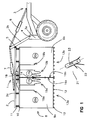
- a decoy device 1 according to a first embodiment comprises a support 2 affecting the form of a gallows comprising an arm horizontal 2a connected by a first articulation 5 to an arm tilted 2b.
- the bracket 2 is fixed by means of a second articulation 4 to a front part 3a of a vehicle 3 of which only the front wheels are shown here.
- a first hydraulic cylinder 6 makes it possible to adjust the angle between the inclined arm 2b and the front part 3a of the vehicle.
- a second hydraulic cylinder 7 makes it possible to adjust the angle between the horizontal arm 2a and the inclined arm 2b.
- the support 2 carries a flag 8 which is here constituted by two flexible panels 9a, 9b.
- Each panel 9a, 9b is integral with an upper rod 10 which is suspended from the horizontal arm 2a by via flexible connection means 11, for example springs.
- Each panel has a square shape of 2m side. He is wearing also weights 12 secured to its lower edge 13a, 13b.
- the panels are uniformly stretched by the weights 12 and they form a substantially flat surface and vertical hanging from the stem 2.
- Cylinders 6 and 7 allow the position of the flag 8 in relation to the ground.
- the flatness of the flag is reinforced by staples 14 which link the panels together.
- the panels are made from a sheet of plastic or woven material of a few tenths of a mm thick, they have a reflective surface of the light on each side, surface which is obtained for example by metallization.
- Each panel has a heating element 15a, 15b which consists of a flexible conductive element which is fixed at a first part 17a, 17b of the panel, located substantially in the middle of the side 16a, 16b of the panel 9a, 9b which is in contact with the neighboring panel and carries the clips 14 of fixation.
- the conductive elements will be produced for example by screen printing of an electrically conductive composition or by fixing flexible metallic conductors to the panel surface. If the panel material is good thermal insulator, we can also have an element heating on each side of the panel to ensure infrared emissivity of the same level on both sides of the panel.
- the conductive elements 15a and 15b are connected independently of each other to a current source 18 which is a means of controlling the temperature of the elements conductors.
- the control means 18 will include a generator current allowing intensity control.
- the temperature control will be ensured by the control means 18 from a programming of desired temperatures (stored in medium 18), and thanks to a reading of the real temperature of the panels 9a, 9b obtained by the temperature sensors 19a, 19b which are also connected to the control module 18.
- the temperature sensors will for example be thermistors or thermo couples.
- the heating elements 15a, 15b have a shape which ensures during heating element operation producing a thermal gradient between the first part 17a, 17b of the panel and a second peripheral part 20a, 20b of the sign.
- This shape here is substantially a sinusoidal curve damped with maximum amplitude at the side 16a, 16b of the panel and decreases when the heating element goes away on this side.
- the control means 18 will be adjusted so as to obtain a temperature at the central zone 17a, 17b of the flag 8 which will be between 5 ° and 10 ° higher than the ambient temperature over an area of approximately 0.5 m 2 .
- the emissivity in the Infrared domain of the flag is therefore close to that of an armored vehicle.
- the energy consumption of such a device is some tens of watt hours, the batteries of the sufficient to ensure the supply of such energy.
- the shape of the conductors will be chosen so as to ensure the desired temperature level.
- the sensors temperature 19a, 19b will control the level of temperature.
- the flag according to the invention constitutes a decoy for a roadside mine 21.
- a mine is disposed usually on a tripod 22 along a route of passage of armored vehicles. It includes a target 23 which generally combines infrared detection and a laser rangefinder.
- the device according to the invention When the device according to the invention passes in front of the target sensor 23 of mine 21, the latter detects a hot spot whose infrared signature is close to that of a vehicle.
- the rangefinder laser beam is reflected by the metallized surface of the panels 9a, 9b, which for the mine provides confirmation of the presence of a target of a length equivalent to that of a combat vehicle.
- the firing of mine 21 is therefore caused by the device lure according to the invention.
- the flexible panels 9a, 9b are light and inexpensive, they are easily replaced as a result of their destruction by the mine, and the demining vehicle retains all of its mobility.
- the panels can also be sufficiently thin so as not to trigger the explosion of the projectile fired by the mine during its impact on the flag.
- a device could be defined in which the flag would consist of a single panel.
- one or more can be provided rewinder systems integral with the support and allowing the winding of each panel.
- the reels will be preferably motorized. This winding is made possible by the flexibility of the material of the panels. We thus facilitates the mobility of the device, the panels can be easily deployed or folded. The length deployed of each panel which can also be modified.
- each panel in the form of a sheet of a conductive polymer of the heat to which a conductive mesh will be applied flexible.
- This structure will be covered on both sides by a protective sheet which will be reflective (by example metallized plastic).
- This structure will be easily rollable.
- Figure 2 shows a decoy device according to a second embodiment of the invention.
- This device differs from the previous one by the structure of the flag 8 which is not here formed by two panels but by the juxtaposition of several rectangular strips 24 at the way of a flexible curtain. Each strip is metallized on its two sides to ensure its reflective character.
- some of the bands 24 carry a heating element 15 consisting of an element flexible conductor bonded or screen printed on the surface of the band (and possibly symmetrically on both sides of each strip to ensure infra-emissivity the same level on either side of the flag).
- the bands 24a, 24b, 24c, 24d, 24e, 24f and 24g carry a heating element (respectively 15a, 15b, 15c, 15d, 15th, 15f and 15g).
- Each heating element 15 is connected to the means 18 controlling its temperature.
- the heating surface of the heating elements 15 is different depending on the band considered. So the band central 24a carries a heating element 15a whose length is greater than that of the heating elements carried by the neighboring bands 24b and 24c.
- the peripheral bands 24f and 24g are those for which the heating element has a minimum length. The central band can therefore be worn at a temperature higher than that of the side bands.
- the curve formed by the juxtaposition of different heating elements have here substantially the shape a damped sinusoid on either side of the strip central 24a.
- Each strip 24 can also carry a temperature 19 which is connected to the control means 18 and which allows measurement of the actual strip temperature considered.
- the temperature of each heating element carried by a strip is slaved by the control means 18 to a value different for each band.
- the operation of this device is the same as that previously described.
- the mine sensor 23 will detect a hot spot at a central part 17 of the flag.
- the range finder laser will be reflected from the surface of the bands and the mine will be initiated.
- the strips can be placed with the hottest parts backwards so simulate vehicles whose hot spot is the pot exhaust (located towards the rear).
- FIG. 3 shows an alternative embodiment in which each strip 24 carries at least one conductive element flexible 15 which extends longitudinally between an edge upper 25 and a lower edge 13 of the strip 24 and which has at least one ripple.
- the band will wear possibly two symmetrical conductors, one on each face.
- the flag 8 here comprises ten bands numbered 24a to 24d.
- the central bands 24e, 24f and 24g have conductors 15 which are wavy evenly over substantially the entire length of the strip.
- the front strips 24a, 24b, 24c and 24d have conductors 15 which are waved regularly only at the level of the lower half of the strip.
- the rear bands 24, 24i and 24d also have conductors which are only wavy at the level of half bottom of the strip, but the undulations made on these bands have a variable shape along each band. Ripples of reduced period 26 are thus followed by ripples 27 of wider period.
- Each conductive element 15 is connected by means of temperature control 18.
- a temperature sensor 19 being moreover arranged at the level of each strip at near the area heated by the conductive element.
- Zone B will be controlled at a temperature that will be between 15 ° and 20 ° above room temperature and which will be greater than that of zone A (which will itself be brought to a temperature between 5 ° and 10 ° above the temperature ambient).
- the whole flag appears roughly the silhouette of an armored vehicle A whose compartment motor corresponds to zone B.
- the advantage of this variant is that it is easy to move the hot spot to simulate different vehicles (for example to the rear exhaust pipe).
- Figure 4 shows a third embodiment of the device according to the invention.
- flag 8 is produced by a mosaic of plates 28 which are connected to each other by removable connecting means 29, by example by repositionable rings.
- the plates will be made for example of aluminum.
- All plates are covered with material light reflecting and some plates have heating elements, for example resistors electrical or conductors (not shown) arranged on each side of each plate and connected by means of temperature control 18.
- heating elements for example resistors electrical or conductors (not shown) arranged on each side of each plate and connected by means of temperature control 18.
- Each hot plate will also carry a temperature (not shown).
- each plate can be controlled from individually by means 18, so it is possible to give flag 8 an infrared signature close to that of a real vehicle.
- flag 8 an infrared signature close to that of a real vehicle.
- Figure 4 a number of heated plates, arranged substantially in the middle of the flag 8 and which delimit the silhouette Z of a armored vehicle.
- the plates 28a and 28b are heated to a temperature higher than that of their neighbors so as to appear simulate the location of the engine compartment.
- the seismic signal can be obtained using wheels or tracks integral with the vehicle and having a profile appropriate.
- the vehicle 3 can be teleoperated to starting, for example, from a follower vehicle. We will thus increase the security of the demining operation.
- the invention can finally be applied to other types of deception than that of roadside mines, especially at the simulation of armored vehicles for site protection or an area against attacks by guided missiles infrared.
Landscapes
- Engineering & Computer Science (AREA)
- General Engineering & Computer Science (AREA)
- Remote Sensing (AREA)
- Radar, Positioning & Navigation (AREA)
- Electromagnetism (AREA)
- Physics & Mathematics (AREA)
- Aviation & Aerospace Engineering (AREA)
- Aiming, Guidance, Guns With A Light Source, Armor, Camouflage, And Targets (AREA)
- Electrotherapy Devices (AREA)
- Measuring Pulse, Heart Rate, Blood Pressure Or Blood Flow (AREA)
- Measurement And Recording Of Electrical Phenomena And Electrical Characteristics Of The Living Body (AREA)
- Preparation Of Clay, And Manufacture Of Mixtures Containing Clay Or Cement (AREA)
- Noodles (AREA)
- General Preparation And Processing Of Foods (AREA)
- Optical Radar Systems And Details Thereof (AREA)
Applications Claiming Priority (2)
| Application Number | Priority Date | Filing Date | Title |
|---|---|---|---|
| FR9906380 | 1999-05-18 | ||
| FR9906380A FR2793877B1 (fr) | 1999-05-18 | 1999-05-18 | Dispositif de leurrage |
Publications (2)
| Publication Number | Publication Date |
|---|---|
| EP1054230A1 true EP1054230A1 (de) | 2000-11-22 |
| EP1054230B1 EP1054230B1 (de) | 2003-07-09 |
Family
ID=9545783
Family Applications (1)
| Application Number | Title | Priority Date | Filing Date |
|---|---|---|---|
| EP00401178A Expired - Lifetime EP1054230B1 (de) | 1999-05-18 | 2000-04-28 | Täuscheinrichtung zum Irreführen einer Landmine |
Country Status (6)
| Country | Link |
|---|---|
| US (1) | US6561072B1 (de) |
| EP (1) | EP1054230B1 (de) |
| AT (1) | ATE244867T1 (de) |
| DE (1) | DE60003754T2 (de) |
| ES (1) | ES2199748T3 (de) |
| FR (1) | FR2793877B1 (de) |
Cited By (4)
| Publication number | Priority date | Publication date | Assignee | Title |
|---|---|---|---|---|
| FR2939504A1 (fr) * | 2008-12-10 | 2010-06-11 | Mbda France | Materiel roulant pour declencher des charges explosives |
| FR2939503A1 (fr) * | 2008-12-10 | 2010-06-11 | Mbda France | Dispositif pour declencher a distance des charges explosives |
| FR2939502A1 (fr) * | 2008-12-10 | 2010-06-11 | Mbda France | Materiel roulant pour declencher des charges explosives et ensemble motorise pour securiser des routes, pistes ou analogues |
| EP2236976A1 (de) | 2009-04-03 | 2010-10-06 | Eca | Täuscheinrichtung, insbesondere für eine unkonventionelle Spreng- oder Brandvorrichtung |
Families Citing this family (4)
| Publication number | Priority date | Publication date | Assignee | Title |
|---|---|---|---|---|
| SE524835C2 (sv) * | 2003-05-09 | 2004-10-12 | Saab Ab | Termisk målanordning med strömslingor |
| US20080134872A1 (en) * | 2005-12-22 | 2008-06-12 | Stuart Owen Goldman | Forced premature detonation of improvised explosive devices via chemical substances |
| US7698981B2 (en) * | 2005-12-22 | 2010-04-20 | Alcatel-Lucent Usa Inc. | Forced premature detonation of improvised explosive devices via noise print simulation |
| US8909385B2 (en) | 2011-01-14 | 2014-12-09 | Alliant Techsystems Inc. | Infrared signature matching system, control circuit, and related method |
Citations (6)
| Publication number | Priority date | Publication date | Assignee | Title |
|---|---|---|---|---|
| US4346901A (en) * | 1981-03-25 | 1982-08-31 | Sperry Corporation | Live fire thermal target |
| US4814585A (en) * | 1985-06-15 | 1989-03-21 | Dan Klein | Textile or fabric and method of production |
| USH679H (en) * | 1988-03-24 | 1989-09-05 | The United States Of America As Represented By The Secretary Of The Army | Foldable towable thermal and radar vehicular decoy |
| USH694H (en) * | 1988-03-24 | 1989-10-03 | The United States Of America As Represented By The Secretary Of The Army | Movable thermal and radar vehicular decoy |
| DE19642037A1 (de) * | 1996-10-11 | 1998-04-16 | Kreco Kreiner Consulting Ges F | Heizdecke |
| US5814754A (en) * | 1997-01-09 | 1998-09-29 | Foster-Miller, Inc. | False target deployment system |
Family Cites Families (13)
| Publication number | Priority date | Publication date | Assignee | Title |
|---|---|---|---|---|
| US4240212A (en) * | 1979-06-21 | 1980-12-23 | The United States Of America As Represented By The Secretary Of The Navy | Thermal signature targets |
| CH649378A5 (de) * | 1980-09-04 | 1985-05-15 | Polytronic Ag | Schiessziel mit einer eine silhouettenfoermige bildmarkierung tragende zielscheibe. |
| US4422646A (en) * | 1981-09-18 | 1983-12-27 | Tvi Energy Corporation | Infrared target for military applications and its use |
| US4546983A (en) * | 1981-09-18 | 1985-10-15 | Tvi Energy Corporation | Multi-spectral target |
| US4659089A (en) * | 1981-09-18 | 1987-04-21 | Tvi Energy Corporation | Multi-spectral target |
| DE3804991C1 (de) * | 1988-02-18 | 1999-07-08 | Lfk Gmbh | Einrichtung zum Schutz von Aktiv-Panzerungen |
| DE4242541C2 (de) * | 1992-12-16 | 1996-03-28 | Tzn Forschung & Entwicklung | Vorrichtung zum Orten von unterhalb der Erdoberfläche befindlicher Munition |
| DE19502455C2 (de) * | 1995-01-27 | 1996-12-05 | Lobbe Xenex Gmbh | Vorrichtung zum Aufspüren von im Erdreich befindlichen Gegenständen, insbesondere explosiver Gegenstände |
| US6257262B1 (en) * | 1995-09-22 | 2001-07-10 | The United States Of America As Represented By The Secretary Of The Army | Building shape modification camouflage structures |
| DE19619135C2 (de) * | 1996-05-11 | 1999-03-25 | Rheinmetall Ind Ag | Unbemanntes gepanzertes Minenräumfahrzeug |
| FR2753263B1 (fr) * | 1996-09-12 | 1998-10-30 | France Etat | Cible terrestre pour simuler la silhouette thermique d'un vehicule, tel qu'un char |
| US6338292B1 (en) * | 1999-09-30 | 2002-01-15 | Robert Fisher Reynolds | Thermal and visual camouflage system |
| US6337475B1 (en) * | 2000-02-24 | 2002-01-08 | The United States Of America As Represented By The Secretary Of The Army | Thermal silhouette target and zeroing technique |
-
1999
- 1999-05-18 FR FR9906380A patent/FR2793877B1/fr not_active Expired - Fee Related
-
2000
- 2000-04-26 US US09/558,626 patent/US6561072B1/en not_active Expired - Lifetime
- 2000-04-28 AT AT00401178T patent/ATE244867T1/de not_active IP Right Cessation
- 2000-04-28 EP EP00401178A patent/EP1054230B1/de not_active Expired - Lifetime
- 2000-04-28 DE DE60003754T patent/DE60003754T2/de not_active Expired - Lifetime
- 2000-04-28 ES ES00401178T patent/ES2199748T3/es not_active Expired - Lifetime
Patent Citations (6)
| Publication number | Priority date | Publication date | Assignee | Title |
|---|---|---|---|---|
| US4346901A (en) * | 1981-03-25 | 1982-08-31 | Sperry Corporation | Live fire thermal target |
| US4814585A (en) * | 1985-06-15 | 1989-03-21 | Dan Klein | Textile or fabric and method of production |
| USH679H (en) * | 1988-03-24 | 1989-09-05 | The United States Of America As Represented By The Secretary Of The Army | Foldable towable thermal and radar vehicular decoy |
| USH694H (en) * | 1988-03-24 | 1989-10-03 | The United States Of America As Represented By The Secretary Of The Army | Movable thermal and radar vehicular decoy |
| DE19642037A1 (de) * | 1996-10-11 | 1998-04-16 | Kreco Kreiner Consulting Ges F | Heizdecke |
| US5814754A (en) * | 1997-01-09 | 1998-09-29 | Foster-Miller, Inc. | False target deployment system |
Cited By (12)
| Publication number | Priority date | Publication date | Assignee | Title |
|---|---|---|---|---|
| FR2939504A1 (fr) * | 2008-12-10 | 2010-06-11 | Mbda France | Materiel roulant pour declencher des charges explosives |
| FR2939503A1 (fr) * | 2008-12-10 | 2010-06-11 | Mbda France | Dispositif pour declencher a distance des charges explosives |
| FR2939502A1 (fr) * | 2008-12-10 | 2010-06-11 | Mbda France | Materiel roulant pour declencher des charges explosives et ensemble motorise pour securiser des routes, pistes ou analogues |
| EP2196762A1 (de) | 2008-12-10 | 2010-06-16 | MBDA France | Rollendes Material zum Auslösen von Sprengladungen und motorisierte Einheit zum Sichern von Straßen, Pisten und Ähnlichem |
| EP2196761A1 (de) * | 2008-12-10 | 2010-06-16 | MBDA France | Vorrichtung zur Fernauslösung von Sprengladungen |
| WO2010067000A1 (fr) * | 2008-12-10 | 2010-06-17 | Mbda France | Dispositif pour declencher a distance des charges explosives |
| WO2010066997A1 (fr) * | 2008-12-10 | 2010-06-17 | Mbda France | Materiel roulant pour declencher des charges explosives et ensemble motorise pour securiser des routes, pistes ou analogues. |
| US8522661B2 (en) | 2008-12-10 | 2013-09-03 | Mbda France | Mobile equipment for detonating explosives and a motorized unit for securing roads, tracks or similar |
| US8541717B2 (en) | 2008-12-10 | 2013-09-24 | Mbda France | Device for remotely detonating explosives |
| EP2236976A1 (de) | 2009-04-03 | 2010-10-06 | Eca | Täuscheinrichtung, insbesondere für eine unkonventionelle Spreng- oder Brandvorrichtung |
| FR2944100A1 (fr) * | 2009-04-03 | 2010-10-08 | Eca | Dispositif de leurrage notamment pour engin explosif improvise. |
| EP2719992A1 (de) | 2009-04-03 | 2014-04-16 | Eca | Täuscheinrichtung, insbesondere für eine unkonventionelle Spreng- oder Brandvorrichtung |
Also Published As
| Publication number | Publication date |
|---|---|
| FR2793877B1 (fr) | 2002-05-17 |
| ES2199748T3 (es) | 2004-03-01 |
| DE60003754T2 (de) | 2004-01-29 |
| US6561072B1 (en) | 2003-05-13 |
| ATE244867T1 (de) | 2003-07-15 |
| DE60003754D1 (de) | 2003-08-14 |
| EP1054230B1 (de) | 2003-07-09 |
| FR2793877A1 (fr) | 2000-11-24 |
Similar Documents
| Publication | Publication Date | Title |
|---|---|---|
| EP1054230B1 (de) | Täuscheinrichtung zum Irreführen einer Landmine | |
| EP2196762B1 (de) | Rollendes Material zum Auslösen von Sprengladungen und motorisierte Einheit zum Sichern von Straßen, Pisten und Ähnlichem | |
| FR2778977A1 (fr) | Dispositif de protection de blindage actif | |
| EP1266260A1 (de) | Zielgerät mit vier festen reflektierenden oberflächen | |
| EP0127496A1 (de) | Vorrichtung zur Erzeugung infraroter oder ultravioletter Strahlung | |
| FR2790731A1 (fr) | Procede de simulation des flux thermiques externes absorbes en vol par les elements radiatifs exterieurs d'un engin spatial et engin spatial pour la mise en oeuvre de ce procede | |
| FR2733311A1 (fr) | Dispositif de camouflage auto-adaptatif | |
| EP0829697B1 (de) | Landzielscheibe zum Simulieren von der thermischen Form eines Fahrzeugs wie zum Beispiel eines Panzerfahrzeugs | |
| EP1054370B1 (de) | Vorrichtung zum Schutz eines Gebietes gegen Eindringen | |
| FR2544067A1 (fr) | Dispositif de cible fixe ou mobile pour simuler la silhouette thermique d'un vehicule | |
| FR2517172A1 (fr) | Ecran thermique | |
| BE1006541A3 (fr) | Leurre multispectral. | |
| EP2236976B1 (de) | Täuscheinrichtung, insbesondere für eine unkonventionelle Spreng- oder Brandvorrichtung | |
| FR3030016B1 (fr) | Systeme de signalisation lumineuse | |
| CA2744879C (fr) | Dispositif pour declencher a distance des charges explosives | |
| EP0776815A1 (de) | Antriebsverfahren für ein Fahrzeug mit schlängelnder Fortbewegung und Fahrzeug zur Durchführung des Verfahrens | |
| EP1856552B1 (de) | Gegenmassnahmevorrichtung zur bedrohungsverfolgung in form eines zielsuchkopfflugkörper | |
| FR2761407A1 (fr) | Dispositif de dissimulation thermique d'une source de rayonnements infrarouges, notamment d'un moteur a combustion interne de vehicule | |
| FR2939504A1 (fr) | Materiel roulant pour declencher des charges explosives | |
| EP1767753B1 (de) | Vorrichtung zum Infrarotunsichtbarmachen einer Abgasleitung eines Kraftfahrzeuges | |
| EP0762367B1 (de) | Matrixanzeigetafel | |
| EP1006334B1 (de) | Wärmeziel | |
| FR2678366A1 (fr) | Dispositif de camouflage multi-spectral d'un galet d'un train de roulement d'un vehicule. | |
| FR2481785A1 (fr) | Surfaces pour capteur solaire | |
| FR2700607A1 (fr) | Ensemble de chauffe par rayonnement à surface émissive non plane. |
Legal Events
| Date | Code | Title | Description |
|---|---|---|---|
| PUAI | Public reference made under article 153(3) epc to a published international application that has entered the european phase |
Free format text: ORIGINAL CODE: 0009012 |
|
| AK | Designated contracting states |
Kind code of ref document: A1 Designated state(s): AT BE CH CY DE DK ES FI FR GB GR IE IT LI LU MC NL PT SE |
|
| AX | Request for extension of the european patent |
Free format text: AL;LT;LV;MK;RO;SI |
|
| 17P | Request for examination filed |
Effective date: 20010108 |
|
| AKX | Designation fees paid |
Free format text: AT BE CH CY DE DK ES FI FR GB GR IE IT LI LU MC NL PT SE |
|
| GRAH | Despatch of communication of intention to grant a patent |
Free format text: ORIGINAL CODE: EPIDOS IGRA |
|
| GRAH | Despatch of communication of intention to grant a patent |
Free format text: ORIGINAL CODE: EPIDOS IGRA |
|
| GRAA | (expected) grant |
Free format text: ORIGINAL CODE: 0009210 |
|
| AK | Designated contracting states |
Designated state(s): AT BE CH CY DE DK ES FI FR GB GR IE IT LI LU MC NL PT SE |
|
| PG25 | Lapsed in a contracting state [announced via postgrant information from national office to epo] |
Ref country code: NL Free format text: LAPSE BECAUSE OF FAILURE TO SUBMIT A TRANSLATION OF THE DESCRIPTION OR TO PAY THE FEE WITHIN THE PRESCRIBED TIME-LIMIT Effective date: 20030709 Ref country code: CY Free format text: LAPSE BECAUSE OF FAILURE TO SUBMIT A TRANSLATION OF THE DESCRIPTION OR TO PAY THE FEE WITHIN THE PRESCRIBED TIME-LIMIT Effective date: 20030709 Ref country code: FI Free format text: LAPSE BECAUSE OF FAILURE TO SUBMIT A TRANSLATION OF THE DESCRIPTION OR TO PAY THE FEE WITHIN THE PRESCRIBED TIME-LIMIT Effective date: 20030709 Ref country code: IE Free format text: LAPSE BECAUSE OF FAILURE TO SUBMIT A TRANSLATION OF THE DESCRIPTION OR TO PAY THE FEE WITHIN THE PRESCRIBED TIME-LIMIT Effective date: 20030709 |
|
| REG | Reference to a national code |
Ref country code: GB Ref legal event code: FG4D Free format text: NOT ENGLISH |
|
| REG | Reference to a national code |
Ref country code: CH Ref legal event code: EP |
|
| GBT | Gb: translation of ep patent filed (gb section 77(6)(a)/1977) | ||
| REG | Reference to a national code |
Ref country code: CH Ref legal event code: NV Representative=s name: M. ZARDI & CO. SA |
|
| REF | Corresponds to: |
Ref document number: 60003754 Country of ref document: DE Date of ref document: 20030814 Kind code of ref document: P |
|
| REG | Reference to a national code |
Ref country code: IE Ref legal event code: FG4D Free format text: FRENCH |
|
| PG25 | Lapsed in a contracting state [announced via postgrant information from national office to epo] |
Ref country code: SE Free format text: LAPSE BECAUSE OF FAILURE TO SUBMIT A TRANSLATION OF THE DESCRIPTION OR TO PAY THE FEE WITHIN THE PRESCRIBED TIME-LIMIT Effective date: 20031009 Ref country code: GR Free format text: LAPSE BECAUSE OF FAILURE TO SUBMIT A TRANSLATION OF THE DESCRIPTION OR TO PAY THE FEE WITHIN THE PRESCRIBED TIME-LIMIT Effective date: 20031009 Ref country code: DK Free format text: LAPSE BECAUSE OF FAILURE TO SUBMIT A TRANSLATION OF THE DESCRIPTION OR TO PAY THE FEE WITHIN THE PRESCRIBED TIME-LIMIT Effective date: 20031009 |
|
| NLV1 | Nl: lapsed or annulled due to failure to fulfill the requirements of art. 29p and 29m of the patents act | ||
| PG25 | Lapsed in a contracting state [announced via postgrant information from national office to epo] |
Ref country code: PT Free format text: LAPSE BECAUSE OF FAILURE TO SUBMIT A TRANSLATION OF THE DESCRIPTION OR TO PAY THE FEE WITHIN THE PRESCRIBED TIME-LIMIT Effective date: 20031209 |
|
| REG | Reference to a national code |
Ref country code: IE Ref legal event code: FD4D |
|
| REG | Reference to a national code |
Ref country code: ES Ref legal event code: FG2A Ref document number: 2199748 Country of ref document: ES Kind code of ref document: T3 |
|
| PG25 | Lapsed in a contracting state [announced via postgrant information from national office to epo] |
Ref country code: AT Free format text: LAPSE BECAUSE OF NON-PAYMENT OF DUE FEES Effective date: 20040428 Ref country code: LU Free format text: LAPSE BECAUSE OF NON-PAYMENT OF DUE FEES Effective date: 20040428 |
|
| PG25 | Lapsed in a contracting state [announced via postgrant information from national office to epo] |
Ref country code: MC Free format text: LAPSE BECAUSE OF NON-PAYMENT OF DUE FEES Effective date: 20040430 |
|
| PLBE | No opposition filed within time limit |
Free format text: ORIGINAL CODE: 0009261 |
|
| STAA | Information on the status of an ep patent application or granted ep patent |
Free format text: STATUS: NO OPPOSITION FILED WITHIN TIME LIMIT |
|
| 26N | No opposition filed |
Effective date: 20040414 |
|
| REG | Reference to a national code |
Ref country code: CH Ref legal event code: PUE Owner name: NEXTER SYSTEMS Free format text: GIAT INDUSTRIES#13, ROUTE DE LA MINIERE#78000 VERSAILLES (FR) -TRANSFER TO- NEXTER SYSTEMS#34, BOULEVARD DE VALMY#42300 ROANNE (FR) |
|
| REG | Reference to a national code |
Ref country code: GB Ref legal event code: 732E Free format text: REGISTERED BETWEEN 20090625 AND 20090701 |
|
| REG | Reference to a national code |
Ref country code: CH Ref legal event code: NV Representative=s name: ING. MARCO ZARDI C/O M. ZARDI & CO. S.A. |
|
| REG | Reference to a national code |
Ref country code: ES Ref legal event code: PC2A Owner name: NEXTER SYTEMS Effective date: 20160315 |
|
| REG | Reference to a national code |
Ref country code: FR Ref legal event code: PLFP Year of fee payment: 17 |
|
| REG | Reference to a national code |
Ref country code: FR Ref legal event code: PLFP Year of fee payment: 18 |
|
| PGFP | Annual fee paid to national office [announced via postgrant information from national office to epo] |
Ref country code: CH Payment date: 20170327 Year of fee payment: 18 Ref country code: FR Payment date: 20170322 Year of fee payment: 18 |
|
| PGFP | Annual fee paid to national office [announced via postgrant information from national office to epo] |
Ref country code: GB Payment date: 20170324 Year of fee payment: 18 Ref country code: BE Payment date: 20170323 Year of fee payment: 18 |
|
| PGFP | Annual fee paid to national office [announced via postgrant information from national office to epo] |
Ref country code: ES Payment date: 20170323 Year of fee payment: 18 Ref country code: IT Payment date: 20170322 Year of fee payment: 18 |
|
| PGFP | Annual fee paid to national office [announced via postgrant information from national office to epo] |
Ref country code: DE Payment date: 20170321 Year of fee payment: 18 |
|
| REG | Reference to a national code |
Ref country code: DE Ref legal event code: R119 Ref document number: 60003754 Country of ref document: DE |
|
| REG | Reference to a national code |
Ref country code: CH Ref legal event code: PL |
|
| REG | Reference to a national code |
Ref country code: BE Ref legal event code: MM Effective date: 20180430 Ref country code: BE Ref legal event code: PD Owner name: NEXTER SYSTEMS; FR Free format text: DETAILS ASSIGNMENT: CHANGE OF OWNER(S), AFFECTATION / CESSION; FORMER OWNER NAME: GIAT INDUSTRIES Effective date: 20151223 |
|
| GBPC | Gb: european patent ceased through non-payment of renewal fee |
Effective date: 20180428 |
|
| PG25 | Lapsed in a contracting state [announced via postgrant information from national office to epo] |
Ref country code: DE Free format text: LAPSE BECAUSE OF NON-PAYMENT OF DUE FEES Effective date: 20181101 |
|
| PG25 | Lapsed in a contracting state [announced via postgrant information from national office to epo] |
Ref country code: GB Free format text: LAPSE BECAUSE OF NON-PAYMENT OF DUE FEES Effective date: 20180428 Ref country code: LI Free format text: LAPSE BECAUSE OF NON-PAYMENT OF DUE FEES Effective date: 20180430 Ref country code: BE Free format text: LAPSE BECAUSE OF NON-PAYMENT OF DUE FEES Effective date: 20180430 Ref country code: CH Free format text: LAPSE BECAUSE OF NON-PAYMENT OF DUE FEES Effective date: 20180430 |
|
| PG25 | Lapsed in a contracting state [announced via postgrant information from national office to epo] |
Ref country code: FR Free format text: LAPSE BECAUSE OF NON-PAYMENT OF DUE FEES Effective date: 20180430 Ref country code: IT Free format text: LAPSE BECAUSE OF NON-PAYMENT OF DUE FEES Effective date: 20180428 |
|
| REG | Reference to a national code |
Ref country code: ES Ref legal event code: FD2A Effective date: 20190912 |
|
| PG25 | Lapsed in a contracting state [announced via postgrant information from national office to epo] |
Ref country code: ES Free format text: LAPSE BECAUSE OF NON-PAYMENT OF DUE FEES Effective date: 20180429 |