EP2198672B1 - Procédé pour déterminer des paramètres de fonctionnement d'une lampe à décharge de gaz fonctionnant avec un ballast électronique, et ballast correspondant - Google Patents
Procédé pour déterminer des paramètres de fonctionnement d'une lampe à décharge de gaz fonctionnant avec un ballast électronique, et ballast correspondant Download PDFInfo
- Publication number
- EP2198672B1 EP2198672B1 EP08802680A EP08802680A EP2198672B1 EP 2198672 B1 EP2198672 B1 EP 2198672B1 EP 08802680 A EP08802680 A EP 08802680A EP 08802680 A EP08802680 A EP 08802680A EP 2198672 B1 EP2198672 B1 EP 2198672B1
- Authority
- EP
- European Patent Office
- Prior art keywords
- filament
- heating
- resistance
- current
- ballast
- Prior art date
- Legal status (The legal status is an assumption and is not a legal conclusion. Google has not performed a legal analysis and makes no representation as to the accuracy of the status listed.)
- Not-in-force
Links
- 238000000034 method Methods 0.000 title claims description 27
- 238000010438 heat treatment Methods 0.000 claims abstract description 82
- 101100087528 Mus musculus Rhoj gene Proteins 0.000 claims abstract description 11
- 238000005259 measurement Methods 0.000 claims description 11
- 238000012360 testing method Methods 0.000 claims description 5
- 230000001105 regulatory effect Effects 0.000 claims description 2
- 239000003990 capacitor Substances 0.000 description 5
- 238000001514 detection method Methods 0.000 description 4
- 101150075139 RHOT2 gene Proteins 0.000 description 3
- 230000001419 dependent effect Effects 0.000 description 3
- 238000011161 development Methods 0.000 description 3
- 230000018109 developmental process Effects 0.000 description 3
- 239000002184 metal Substances 0.000 description 3
- 238000006467 substitution reaction Methods 0.000 description 3
- 101100537098 Mus musculus Alyref gene Proteins 0.000 description 2
- 101150095908 apex1 gene Proteins 0.000 description 2
- 230000033228 biological regulation Effects 0.000 description 2
- 230000015572 biosynthetic process Effects 0.000 description 2
- 238000010586 diagram Methods 0.000 description 2
- 230000006870 function Effects 0.000 description 2
- 238000004804 winding Methods 0.000 description 2
- 101100269674 Mus musculus Alyref2 gene Proteins 0.000 description 1
- 238000013459 approach Methods 0.000 description 1
- 230000000052 comparative effect Effects 0.000 description 1
- 230000000694 effects Effects 0.000 description 1
- 238000011156 evaluation Methods 0.000 description 1
- 238000009499 grossing Methods 0.000 description 1
- 230000012447 hatching Effects 0.000 description 1
- 230000001629 suppression Effects 0.000 description 1
Images


Classifications
-
- H—ELECTRICITY
- H05—ELECTRIC TECHNIQUES NOT OTHERWISE PROVIDED FOR
- H05B—ELECTRIC HEATING; ELECTRIC LIGHT SOURCES NOT OTHERWISE PROVIDED FOR; CIRCUIT ARRANGEMENTS FOR ELECTRIC LIGHT SOURCES, IN GENERAL
- H05B41/00—Circuit arrangements or apparatus for igniting or operating discharge lamps
- H05B41/14—Circuit arrangements
- H05B41/26—Circuit arrangements in which the lamp is fed by power derived from DC by means of a converter, e.g. by high-voltage DC
- H05B41/28—Circuit arrangements in which the lamp is fed by power derived from DC by means of a converter, e.g. by high-voltage DC using static converters
- H05B41/295—Circuit arrangements in which the lamp is fed by power derived from DC by means of a converter, e.g. by high-voltage DC using static converters with semiconductor devices and specially adapted for lamps with preheating electrodes, e.g. for fluorescent lamps
-
- H—ELECTRICITY
- H05—ELECTRIC TECHNIQUES NOT OTHERWISE PROVIDED FOR
- H05B—ELECTRIC HEATING; ELECTRIC LIGHT SOURCES NOT OTHERWISE PROVIDED FOR; CIRCUIT ARRANGEMENTS FOR ELECTRIC LIGHT SOURCES, IN GENERAL
- H05B41/00—Circuit arrangements or apparatus for igniting or operating discharge lamps
- H05B41/14—Circuit arrangements
- H05B41/36—Controlling
Definitions
- the invention relates to a method for determining operating parameters of a gas discharge lamp to be operated with an electronic ballast.
- Such a method is according to EP 1519638 A1 known.
- the voltage drop across a resistor located on the primary side of the heating transformer is measured at two different times during the preheating phase.
- the two voltage values thus determined are compared with reference voltage values stored in a memory to determine the lamp type.
- the invention has for its object to find a solution to the above problem.
- the invention has for its object to provide a simple method for detecting the lamp type, which improves the detection reliability compared to the previously known methods.
- the solution according to the invention adopts the principle of resistance measurement, preferably at heating power held constant during the preheating time or at constant heating current, and uses the difference value (distance) from hot and cold resistance instead of the hot resistances to determine the lamp type.
- a certain heating power or a certain heating current is set. This can be done via the specification of a corresponding operating frequency and a corresponding switch-on time or a corresponding duty cycle. If the heating circuit is designed with a power source or current source characteristic, it can be ensured that during the preheating phase, the heating power or the Heating current sets in a certain window, which remains within a certain range of values.
- the prior art has always used heating topologies or control methods with a voltage source characteristic or voltage regulation, which are far less suitable for the method operated here.
- the invention is based on the following finding:
- the measurement of the helical resistance via the helical current and the helical voltage presupposes that the helix is supplied with electrical power. This leads to the heating of the coil. Since the coils are usually made of metal, their resistance increases with temperature. The spiral temperature depends on the heating power supplied to the coil. In qualitative terms, this means that the higher the supplied heating power, the higher the coil resistance. It is now assumed that a second lamp type differs from a first lamp type in that the filament resistance of the second lamp type is twice as large as that of the first lamp type.
- the filament of the second type of lamp is heated less than that of the first type of lamp.
- the thermal resistance increase of the filament of the second lamp type is thus smaller than that of the filament of the first type of lamp. The thermal resistance increase thus counteracts the increase in the coil base resistance, with the result is that the detection reliability of the lamp type is reduced.
- the thermal resistance increase of the Spiral of the second lamp type is higher than the thermal resistance increase of the filament of the first lamp type.
- the thermal resistance enhancement enhances the effect of increasing the coil base resistance, with the result that the detection reliability of the lamp type becomes remarkable.
- a further step can be added to the above-mentioned method steps, namely: Setting at least one operating parameter for the determined lamp type.
- the formation of the differential resistance has the advantage that the influence of the starting temperature for measuring the cold resistance is eliminated.
- the invention further relates to a ballast for at least one gas discharge lamp, with which the inventive method can be performed.
- This ballast is characterized by the features of claims 10 and 14. Further developments are the subject of claims dependent on the claims 10 and 11 claims.
- the current setting means may comprise a control part for the filament current.
- a refinement of the ballast may consist in providing means for setting at least one operating parameter for the determined lamp type.
- the measuring means may comprise a voltage divider connected in parallel with the filament, from which a signal corresponding to the filament voltage is derived.
- To the control part may include a connected in series with the heating coil measuring resistor, from which a measurement signal is derived, which corresponds to the helical current.
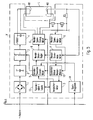
- ballast V is used to operate a gas discharge lamp L with two heating coils W1 and W2.
- a rectifier 1 To generate the operating voltage for the lamp L is rectified by a rectifier 1, the mains voltage and smoothed in a smoothing circuit.
- An inverter 3 generates an alternating voltage which is fed to a series resonant circuit 4. The voltage drop across the capacitor of the series resonant circuit 4 is supplied to the lamp L as the operating voltage.
- a programmer 14 connected to a bus determines the start of a preheat phase for the lamp L. He gives to the block 8 a start signal.
- the block 8 generates the heating power or the filament current for the filaments W1 and W2 of the lamp L.
- the heating power or the filament current are kept constant during the preheating phase.
- the heating power or the filament current are led to the lamp L via a block 6, which contains means for limiting the filament voltage.
- a limitation of the filament voltage is required, for example, a transverse discharge between the individual sections of the heating coils to avoid.
- the filament current flowing through the "cold" filament W2 generates a voltage drop across the resistor R3, which is conducted to the filament current measuring means 7.
- a voltage is further removed, which is a measure of the filament voltage at the "cold” coil W2. This is fed to the helical voltage measuring means 9.
- the measurement values continuously measured by the filament current measuring means 7 and the filament voltage measuring means 9 are fed to a memory 15.
- the memory 15 is controlled by the programmer 14 such that the measured values for the filament current and the filament voltage are stored at two successive times during the preheating phase.
- the stored measured values for the filament current and the filament voltage are fed from the memory 15 from a quotient former 10, which calculates therefrom the cold resistance and the hot resistance of the filament. These values are forwarded by the quotient generator 10 to the difference value generator 11, which calculates the differential resistance therefrom.
- the difference value generator 11 supplies the differential resistance to a decision logic 13, which in turn corresponds to a memory 12 by storing a table for reference differential resistances.
- the decision logic 13 compares the differential resistance calculated in the block 11 with the reference values in the table stored in the memory 12 and determines the type of the lamp L operated by the ballast V.
- the determined lamp type is reported by the decision logic 13 to the operating parameter setting means 5, the next other operating parameters, among other things, the heating current or adjust the heating power, if the lamp L is of a different type than the previously operated with the ballast V lamp.
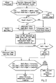
- Fig. 2 concerns the case that two ballasts are operated in parallel with one ballast. Of course, it also includes the possibility of working with only one lamp.
- the cold resistances Rcold1 and Rcold2 are measured by the two lamps. From the two measured values, the absolute value of the difference
- Mains reset or emergency lighting operation is a brief interruption of the mains supply or a brief drop in the mains voltage, which results in a shutdown and a subsequent restart of the electronic ballast. Such a case can be caused by switching the network (by the utility) or by disturbances in the network.
- An emergency lighting operation may e.g. in the event of mains voltage failure, switching on a (buffered) DC and AC supply voltage or switching to battery operation.
- the differential resistance Rdiff is smaller than a predefined substitution resistance value Rsub. This comparison is to check whether the lamp is replaced for test purposes by a so-called substitution resistance, which shows no temperature-dependent resistance due to the thermal conditions. If this is the case, the cold resistance and the hot resistance do not differ. Therefore, if the decision is "Yes", the differential resistance Rdiff is set equal to the hot resistance Rhot.
- the decision is whether the differential resistance Rdiff is smaller than a first stored resistance value "Level 1". If difference resistance Rdiff is less than this level 1, then the decision is made that this is the lamp type 1.
- Fig. 3 shows the course of the filament resistance in three different lamp types during the preheat phase, which takes 500 ms.
- the cold resistance Rcold1 x 2 WW In the first coil, the cold resistance Rcold1 x 2 WW, and the hot resistance Rhot1 y 2 WW; where WW stands for a resistance value unit.
- the cold resistance Rcold2 x 3 WW In the helix of the second lamp type, the cold resistance Rcold2 x 3 WW. During the pre-heating phase it rises to the hot resistance Rhot2 with x 5 WW.
- the filament of the third lamp type starts with the cold resistance Rcold3 at x 4 WW. This resistance increases during the preheat phase to the hot resistor Rhot3 with x 11 WW.
- the spreading of the hot resistors Rhot1, Rhot2 and Rhot3 makes it possible to define for the differential resistors Rdiff1, Rdiff2 and Rdiff3 variation ranges which are spaced from each other.
- the variation ranges are marked with hatching lines.
- a secure identification is in any case given if the determined difference resistance of the heating coil of a lamp falls into one of the three hatched areas.
- the first level “level 1" is identical to the cold resistance Rcold1 of the first lamp type.
- the second level “level 2” is identical to the hot resistance Rhot2 of the second type of lamp.
- the third level “level 3” lies with a considerable distance above the hot resistance Rhot3 of the lamp type.
- dashed lines show that the ranges of determination for the relevant lamp type extend beyond the lower undefined range to the next level.
- the identification zones that go beyond the hatched areas are not compulsory, but have been chosen on a case-by-case basis. It is essential that the hatched areas, ie the variation ranges for the differential resistances, allow identification of the lamp type with great certainty.
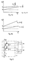
- Fig. 4a shows the dependence of the coil resistance R w as a function of the filament voltage U w .
- Two coils are considered, one having a helix resistance R 1 and the other having a helix resistance R 2 .
- the coils are usually made of metal.
- the electrical resistance of metal increases with temperature. Without taking into account the thermal resistance increase, the two helices form a parallel line to the abscissa, which is indicated by dashed lines. Taking into account the thermal resistance increase, the resistances of the two coils increase with increasing the filament voltage.
- the supplied heating power with impressed helix tension P 1 U 2 w / R.
- the supplied heating power with impressed filament voltage P 2 U 2 w / 2R.
- the helix with the base resistance R 2 supplied heating power P 2 is thus only half as large as the heating power P 1 , which is supplied to the coil with the base resistor R 1 .
- the two curves approach each other with increasing helix voltage U w . As a result, it becomes more difficult to distinguish between two lamp types having the different coil resistances R 1 and R 2 by the thermal resistance increase.
- Fig. 4b now shows the idea underlying the invention, namely not to use an impressed filament voltage U w , but an impressed helical current I w .
- a voltage originating from a low-voltage source predetermined coil voltage is applied to the coil, and that then the resulting helical current is measured.
- the helical resistance R w then results from the product of filament voltage and filament current.
- Fig. 5 shows a gas discharge lamp L, which is connected to an electronic ballast V formed according to the invention.
- the ballast V includes a connected to the AC mains bridge rectifier 1, which rectifies the mains voltage, and a DC voltage intermediate circuit 2 supplies.
- the intermediate circuit 2 is followed by a half-bridge inverter 3, the contains two alternately clocked switches.
- the inverter 3 is followed by a pure resonant circuit, which consists of a choke and a capacitor.
- the lamp is connected in parallel with the capacitor.
- the circuit parts 1 to 4 are common and known in ballasts.
- the ballast should now be designed so that with him fluorescent lamps L of different types can be operated.
- the individual types differ not only by external dimensions, but also by different operating parameters, such as lamp current, lamp voltage, filament voltage, filament current, preheating, etc.
- the ballast automatically detects the lamp type, by measuring the resistance at least one of the two filaments of the fluorescent lamp L.
- the filament resistors of certain types are very close to each other, so that a distinction is difficult, and - as above in connection with Fig. 4a was explained by the thermal heating is still difficult.
- the principle of the regulated helical current is used, which in connection with Fig. 4b has been described.
- the coils of the lamp L Before the lamp type has been determined, the coils of the lamp L firstly a predetermined known Wendelstram must be supplied.
- This helical current is either stored in the block 5 representing operating parameter setting means or in a starting program (or programmer) 14 which transmits the relevant current value to the block 5 when it receives a corresponding command from a center via the bus Usus.
- the thus transmitted current value is supplied from the operating parameter setting means 5 a Wendelstromregier 8, which in turn causes Wendelschreibs-generating means 6, the two coils W1 and W2 of the fluorescent lamp L to supply a corresponding filament voltage.
- the voltage applied to the lower coil W2 coil voltage is tapped with a consisting of the resistors R1 and R2 voltage divider and supplied to Wendelwoodsmessstoffn 9, which in turn pass the measured filament voltage value to a quotient-10.
- the filament current flowing through the filament W2 is measured as a voltage drop across a resistor R3 and fed Wendelstrom measuring means 7, which in turn report the measured Wendelstromwert on the one hand to the quotient imager 10 and on the other hand as an actual value to the helical flow controller 8.
- the quotient generator 10 calculates the filament resistance from the measured filament voltage value and the measured filament current value.
- the helix resistance is supplied to comparison means (decision logic) 13 which compares it with the values stored in a table stored in memory means 12.
- the table contains an associated coil resistance for each type of lamp to be operated with the ballast. This is compared with the measured coil resistance.
- the comparison means (decision logic) 13 then report the determined lamp type to the operating parameter setting means 5.
- Last then take the relevant settings on the ballast V before. vicarious this is in the Fig. 5 taken into account by the connection between the operating parameter setting means 5 and the inverter 3.
- the clock frequency and / or the cycle times of the two switches of the inverter can be influenced in this way to set certain operating parameters.
- the quotient generator 10 is dispensable per se. Instead of storing in the storage means 12 a table which contains the correspondence between coil resistance and lamp type, it is also possible to set down a table containing the associated filament voltage for each lamp type - with known preset coil current. In this case, the filament voltage measuring means 9 would have to report the measured filament voltage instead of the heating resistor to the comparator means (decision logic) 13. The message of the filament current measured by the filament current measuring means 7, which in Fig. 5 takes place at the quotient builder 10, then deleted.
- a concrete realization of the helical voltage generating means 6 is shown. These include a flyback converter, consisting of an electronic switch S, a resistor R4 and an inductance, wherein the inductance of the primary winding of a heating transformer T H is formed.
- the bus voltage U Bus lying on the bus is used as the DC voltage source. Instead of the bus voltage U bus , the output voltage of the intermediate circuit 2 can also be used.
- the heating transformer T H has two secondary windings, each of which is intended for a filament of the fluorescent lamp L.
- the AC voltage transmitted by the heating transformer T H is rectified by the diode 01 and 02 and by the Smoothed capacitors C1 and C2.
- the capacitors C1 and C2 still have the task to contribute to the radio interference suppression.
Landscapes
- Circuit Arrangements For Discharge Lamps (AREA)
- Control Of Resistance Heating (AREA)
Claims (17)
- Procédé pour la détermination de paramètres de fonctionnement d'une lampe à décharge de gaz (L) fonctionnant avec un ballast électronique (V), le procédé comprenant les étapes suivantes :a) préchauffage d'au moins un filament de chauffage (W1, W2),b) mesure directe ou indirecte de la tension de filament (UW),c) détermination de la valeur d'un paramètre d'exploitation devant être choisie, la détermination étant faite en comparant des valeurs de mesure à des valeurs de référence stockées,
caractérisé en ce qued) la mesure directe ou indirecte de la tension de filament (UW) est effectuée en au moins deux moments différents,e1) pendant la mesure entre les deux moments, le courant de filament ou la puissance de chauffage fournie au filament est maintenu(e) constant(e), oue2) au début de la phase de préchauffage, une puissance de chauffage prédéterminée ou un courant de chauffage prédéterminé est ajusté(e),
dans lequel procédé :f) en outre le courant de chauffage est mesuré,g) à partir des valeurs de mesure de la tension de filament et du courant de filament, la résistance à froid (Rcold) est calculée au premier moment et la résistance à chaud (Rhot) est calculée au deuxième moment,h) la résistance différentielle (Rdiff) est calculée à partir de la résistance à chaud (Rhot) et de la résistance à froid (Rcold), eti) la résistance différentielle (Rdiff) déterminée selon l'étape h) est utilisée comme valeur de mesure qui est à comparer avec les valeurs de référence stockées pour déterminer un paramètre de fonctionnement. - Procédé selon la revendication 1,
caractérisé en ce que
l'étape (e1) est réalisée par une régulation du courant de filament ou de la puissance de chauffage. - Procédé selon l'une des revendications 1 ou 2, caractérisé par l'étape supplémentaire :i) ajustement d'au moins un paramètre de fonctionnement pour le type de lampe déterminé.
- Procédé selon l'une des revendications 1 à 3,
caractérisé en ce que
des jeux de valeurs de référence sont stockés, lesquels sont valables pour différentes valeurs de préchauffage, comme le courant de filament, la tension de filament ou la puissance de chauffage. - Procédé selon l'une des revendications 1 à 3,
caractérisé en ce que - si le ballast (V) doit faire fonctionner plusieurs lampes (L1, L2) - une vérification est faite pour établir si les lampes sont du même type. - Procédé selon la revendication 5,
caractérisé en ce que
pour effectuer la vérification de l'identité du type de lampe, la différence des résistances à froid (Rcold) de respectivement deux lampes (L1, L2) est calculée et comparée à une première valeur de référence (Rref1),
et ce qu'une non identité est constatée lorsque la différence est plus grande que la première valeur de référence. - Procédé selon l'une des revendications 1 à 6,
caractérisé en ce que - si le ballast (V) doit faire fonctionner plusieurs lampes (L1, L2) - une vérification est faite pour établir s'il y a pour une lampe une rupture d'un filament de chauffage, dont la chute de tension est mesurée pour calculer la résistance de filament (Rcold, Rhot). - Procédé selon la revendication 7,
caractérisé en ce que
pour effectuer la vérification d'une rupture de filament, la différence des résistances à froid (Rcold) de respectivement deux lampes (L1, L2) est calculée et comparée à une deuxième valeur de référence (Rref2), et en ce qu'une rupture de filament est constatée lorsque la différence est plus grande que la deuxième valeur de référence. - Procédé selon la revendication 8,
caractérisé en ce que - si la mesure des courants de chauffage est effectuée pour plusieurs lampes (L1, L2) fonctionnant avec le ballast (V) via une résistance (R3) commune - en cas d'un diagnostic de rupture d'un filament de chauffage (W1b, W2b), les valeurs des résistances de filament calculées (Rcold, Rhot) sont réduites en fonction de la part du filament cassé dans le nombre total des filaments de chauffage, dont le courant de chauffage traverse la résistance (R3) de mesure. - Circuit, en particulier circuit intégré comme par exemple un ASIC, qui est conçu pour exécuter un procédé selon l'une des revendications précédentes, le circuit déclenchant le préchauffage dudit au moins un filament de chauffage (W1, W2).
- Ballast (V) pour au moins une lampe à décharge de gaz (L) comprenant deux filaments de chauffage (W1, W2), le ballast comprenant un circuit selon la revendication 10, présentant :- des moyens (8) pour produire un courant de filament constant ou une puissance de chauffage constante et pour alimenter au moins un des deux filaments de chauffage (W1, W2) avec le courant de chauffage constant ou la puissance de chauffage constante,- des moyens de mesure (9) pour une mesure directe ou indirecte de la chute de tension aux bornes du filament (W1, W2),- des moyens de programmateur (14), qui définissent deux moments différents pendant la phase de préchauffage, la chute de tension aux bornes du filament (W1, W2) étant mesurée à ces deux moments,- des moyens (7) pour mesurer le courant de filament,- des moyens de stockage (15) pour stocker, aux deux moments déterminés par les moyens de programmateur (14), les valeurs de mesure de la chute de tension aux bornes du filament (W1, W2) et le courant de filament circulant à travers le filament,- des moyens (10) pour calculer les résistances de filament (Rcold, Rhot) aux deux moments déterminés par les moyens de programmateur (14) en formant le quotient des valeurs stockées pour le courant de filament mesuré et de la chute de tension mesurée aux bornes du filament (W1, W2),- des moyens de stockage (12) pour un tableau, dans lequel pour chaque type de lampe une valeur de résistance différentielle de référence est inscrite pour une certaine intensité de courant de filament ou puissance de chauffage, et- des moyens de décision (12) pour déterminer le type de lampe en comparant la résistance différentielle calculée (Rdiff) avec les valeurs de résistance différentielle de référence inscrites dans les moyens de stockage (12).
- Ballast selon la revendication 11,
caractérisé en outre par- des moyens (5) pour l'ajustement d'au moins un paramètre de fonctionnement pour le type de lampe déterminé. - Ballast selon l'une des revendications 11 à 12,
caractérisé en ce que
les moyens (8) pour générer un courant de filament constant ou une puissance de chauffage constante comprennent un régulateur (8) pour le courant de filament ou la puissance de chauffage. - Ballast selon l'une des revendications 11 à 13,
caractérisé en ce que
les moyens de mesure (9) pour une mesure directe ou indirecte de la chute de tension aux bornes du filament (W1, W2) qui est alimenté avec le courant de filament constant prédéfini ou avec la puissance de chauffage constante prédéfinie comprennent un diviseur de tension (R1, R2) monté en parallèle du filament de chauffage. - Ballast selon l'une des revendications 11 à 14,
caractérisé en ce que
pour mesurer le courant de filament (8) une résistance de mesure (R3) est connectée en série avec le filament de chauffage (W1, W2),
et en ce que la chute de tension aux bornes de cette résistance de mesure est utilisée comme valeur de mesure pour le courant de filament. - Ballast selon l'une des revendications 11 à 15,
caractérisé en ce que - si le ballast fait fonctionner deux ou plusieurs lampes (L1, L2) - le courant de filament, qui circule à travers respectivement un filament de chauffage (W1b, W1b) de chacune des lampes, traverse la résistance de chauffage (R3). - Ballast selon l'une des revendications 11 à 16,
caractérisé en ce que,
en cas d'un diagnostic de rupture d'un filament de chauffage (W1b, W2b), la valeur de la résistance de filament (Rcold, Rhot) calculée par les moyens (10) est réduite en fonction de la part du filament cassé dans le nombre total des filaments de chauffage, dont le courant de chauffage traverse la résistance (R3) de mesure.
Applications Claiming Priority (3)
| Application Number | Priority Date | Filing Date | Title |
|---|---|---|---|
| DE102007047142A DE102007047142A1 (de) | 2007-10-02 | 2007-10-02 | Verfahren zum Erkennen des Typs einer mit einem elektronischen Vorschaltgerät zu betreibenden Gasentladungslampe sowie elektronisches Vorschaltgerät |
| DE102008012454A DE102008012454A1 (de) | 2008-03-04 | 2008-03-04 | Verfahren zum Bestimmen von Betriebsparametern einer mit einem elektronischen Vorschaltgerät zu betreibenden Gasentladungslampe sowie ein entsprechendes Vorschaltgerät |
| PCT/EP2008/008236 WO2009046891A1 (fr) | 2007-10-02 | 2008-09-26 | Procédé pour déterminer des paramètres de fonctionnement d'une lampe à décharge de gaz fonctionnant avec un ballast électronique, et ballast correspondant |
Publications (2)
| Publication Number | Publication Date |
|---|---|
| EP2198672A1 EP2198672A1 (fr) | 2010-06-23 |
| EP2198672B1 true EP2198672B1 (fr) | 2011-08-31 |
Family
ID=40193831
Family Applications (1)
| Application Number | Title | Priority Date | Filing Date |
|---|---|---|---|
| EP08802680A Not-in-force EP2198672B1 (fr) | 2007-10-02 | 2008-09-26 | Procédé pour déterminer des paramètres de fonctionnement d'une lampe à décharge de gaz fonctionnant avec un ballast électronique, et ballast correspondant |
Country Status (5)
| Country | Link |
|---|---|
| EP (1) | EP2198672B1 (fr) |
| CN (1) | CN101816219B (fr) |
| AT (1) | ATE523065T1 (fr) |
| DE (1) | DE112008002296A5 (fr) |
| WO (1) | WO2009046891A1 (fr) |
Families Citing this family (3)
| Publication number | Priority date | Publication date | Assignee | Title |
|---|---|---|---|---|
| DE102008022198A1 (de) * | 2008-03-04 | 2009-09-10 | Tridonicatco Gmbh & Co. Kg | Typerkennung einer mit einem elektronischen Vorschaltgerät zu betreibenden Gasentladungslampe |
| JP6110191B2 (ja) * | 2013-04-08 | 2017-04-05 | 日置電機株式会社 | 検査装置および検査処理装置 |
| EP3223588B1 (fr) * | 2016-03-21 | 2020-04-08 | Valeo Iluminacion | Gestion de l'information bin dans un module lumineux pour véhicule automobile comprenant des sources lumineuses à élément semi-conducteur |
Family Cites Families (7)
| Publication number | Priority date | Publication date | Assignee | Title |
|---|---|---|---|---|
| JPH0766864B2 (ja) * | 1989-07-28 | 1995-07-19 | 東芝ライテック株式会社 | 放電灯点灯装置 |
| DE19530485A1 (de) * | 1995-08-18 | 1997-02-20 | Patent Treuhand Ges Fuer Elektrische Gluehlampen Mbh | Verfahren und Schaltungsanordnung zum Betreiben einer elektrischen Lampe |
| EP0889675A1 (fr) * | 1997-07-02 | 1999-01-07 | MAGNETEK S.p.A. | Ballast électronique avec reconnaissance du type de lampe |
| DE19850441A1 (de) * | 1998-10-27 | 2000-05-11 | Trilux Lenze Gmbh & Co Kg | Verfahren und Vorschaltgerät zum Betrieb einer mit einer Leuchtstofflampe versehenen Leuchte |
| DE10345610A1 (de) * | 2003-09-29 | 2005-05-12 | Patent Treuhand Ges Fuer Elektrische Gluehlampen Mbh | Verfahren zum Betreiben mindestens einer Niederdruckentladungslampe |
| WO2005060320A1 (fr) * | 2003-12-11 | 2005-06-30 | Koninklijke Philips Electronics, N.V. | Ballast electronique avec determination de type lampe |
| DE202005013754U1 (de) * | 2005-08-31 | 2005-11-17 | Patent-Treuhand-Gesellschaft für elektrische Glühlampen mbH | Vorschaltgerät für eine Entladungslampe mit adaptiver Vorheizung |
-
2008
- 2008-09-26 EP EP08802680A patent/EP2198672B1/fr not_active Not-in-force
- 2008-09-26 WO PCT/EP2008/008236 patent/WO2009046891A1/fr not_active Ceased
- 2008-09-26 CN CN200880110077.7A patent/CN101816219B/zh not_active Expired - Fee Related
- 2008-09-26 AT AT08802680T patent/ATE523065T1/de active
- 2008-09-26 DE DE112008002296T patent/DE112008002296A5/de not_active Withdrawn
Also Published As
| Publication number | Publication date |
|---|---|
| CN101816219A (zh) | 2010-08-25 |
| CN101816219B (zh) | 2014-04-02 |
| DE112008002296A5 (de) | 2010-09-02 |
| ATE523065T1 (de) | 2011-09-15 |
| WO2009046891A1 (fr) | 2009-04-16 |
| EP2198672A1 (fr) | 2010-06-23 |
Similar Documents
| Publication | Publication Date | Title |
|---|---|---|
| EP1519638B1 (fr) | Méthode pour commander une lampe à décharge basse pression | |
| EP0338109B1 (fr) | Convertisseur pour lampe à décharge | |
| EP2198672B1 (fr) | Procédé pour déterminer des paramètres de fonctionnement d'une lampe à décharge de gaz fonctionnant avec un ballast électronique, et ballast correspondant | |
| DE102007047142A1 (de) | Verfahren zum Erkennen des Typs einer mit einem elektronischen Vorschaltgerät zu betreibenden Gasentladungslampe sowie elektronisches Vorschaltgerät | |
| EP1920642B1 (fr) | Ballast pour une lampe a decharge a prechauffage adaptatif | |
| EP2248395B1 (fr) | Identification du type d'une lampe à décharge destinée à fonctionner avec un ballast électronique | |
| AT517953B1 (de) | Beleuchtungssystem und verfahren zum prüfen, ob mindestens zwei mit einem evg zu betreibende gasentladungslampen vom gleichen typ sind | |
| DE102009019625B4 (de) | Verfahren zum Ermitteln eines Typs einer Gasentladungslampe und elektronisches Vorschaltgerät zum Betreiben von mindestens zwei unterschiedlichen Typen von Gasentladungslampen | |
| EP1492393A1 (fr) | Circuit et méthode pour alimenter une lampe à décharge muni d'une détection de fin de durée de vie | |
| EP2274960B1 (fr) | Procédé et agencement de circuits pour faire fonctionner au moins une lampe à décharge | |
| EP1189488B1 (fr) | Ballast électronique auto-calibrant et méthode de calibrage d'un ballast | |
| EP1920643B1 (fr) | Ballast pour une lampe a decharge a prechauffage adaptatif | |
| DE102008012454A1 (de) | Verfahren zum Bestimmen von Betriebsparametern einer mit einem elektronischen Vorschaltgerät zu betreibenden Gasentladungslampe sowie ein entsprechendes Vorschaltgerät | |
| WO2009109326A1 (fr) | Circuit pour chauffer et surveiller les filaments chauffants d'au moins une lampe à décharge fonctionnant avec un ballast électronique et système d'éclairage | |
| DE102010063933A1 (de) | Betriebsgerät und Verfahren zum Betrieb von Gasentladungslampen | |
| EP1189486B1 (fr) | Ballast électronique | |
| EP2335457B1 (fr) | Determination du type de lampe et topologie du circuit pour plusieurs lampes | |
| WO2012109687A1 (fr) | Procédé d'identification d'un effet schottky dans une lampe à décharge à gradation de lumière | |
| EP2240002A2 (fr) | Appareil de montage électronique destiné au fonctionnement d'au moins deux types différents de lampes à décharge | |
| DE10129453A1 (de) | Elektronisches Vorschaltgerät |
Legal Events
| Date | Code | Title | Description |
|---|---|---|---|
| PUAI | Public reference made under article 153(3) epc to a published international application that has entered the european phase |
Free format text: ORIGINAL CODE: 0009012 |
|
| 17P | Request for examination filed |
Effective date: 20100223 |
|
| AK | Designated contracting states |
Kind code of ref document: A1 Designated state(s): AT BE BG CH CY CZ DE DK EE ES FI FR GB GR HR HU IE IS IT LI LT LU LV MC MT NL NO PL PT RO SE SI SK TR |
|
| AX | Request for extension of the european patent |
Extension state: AL BA MK RS |
|
| RIN1 | Information on inventor provided before grant (corrected) |
Inventor name: DWORATZEK, DIRK Inventor name: DR.ANDRE MITTERBACHER Inventor name: HOEGL, ANDREAS |
|
| RIN1 | Information on inventor provided before grant (corrected) |
Inventor name: HOEGL, ANDREAS Inventor name: MITTERBACHER, ANDRE Inventor name: DWORATZEK, DIRK |
|
| RAP1 | Party data changed (applicant data changed or rights of an application transferred) |
Owner name: TRIDONIC GMBH & CO KG |
|
| 17Q | First examination report despatched |
Effective date: 20101027 |
|
| DAX | Request for extension of the european patent (deleted) | ||
| GRAP | Despatch of communication of intention to grant a patent |
Free format text: ORIGINAL CODE: EPIDOSNIGR1 |
|
| GRAS | Grant fee paid |
Free format text: ORIGINAL CODE: EPIDOSNIGR3 |
|
| GRAA | (expected) grant |
Free format text: ORIGINAL CODE: 0009210 |
|
| AK | Designated contracting states |
Kind code of ref document: B1 Designated state(s): AT BE BG CH CY CZ DE DK EE ES FI FR GB GR HR HU IE IS IT LI LT LU LV MC MT NL NO PL PT RO SE SI SK TR |
|
| REG | Reference to a national code |
Ref country code: CH Ref legal event code: EP Ref country code: GB Ref legal event code: FG4D Free format text: NOT ENGLISH |
|
| REG | Reference to a national code |
Ref country code: IE Ref legal event code: FG4D Free format text: LANGUAGE OF EP DOCUMENT: GERMAN |
|
| REG | Reference to a national code |
Ref country code: DE Ref legal event code: R096 Ref document number: 502008004710 Country of ref document: DE Effective date: 20111103 |
|
| REG | Reference to a national code |
Ref country code: NL Ref legal event code: VDEP Effective date: 20110831 |
|
| LTIE | Lt: invalidation of european patent or patent extension |
Effective date: 20110831 |
|
| PG25 | Lapsed in a contracting state [announced via postgrant information from national office to epo] |
Ref country code: HR Free format text: LAPSE BECAUSE OF FAILURE TO SUBMIT A TRANSLATION OF THE DESCRIPTION OR TO PAY THE FEE WITHIN THE PRESCRIBED TIME-LIMIT Effective date: 20110831 Ref country code: LT Free format text: LAPSE BECAUSE OF FAILURE TO SUBMIT A TRANSLATION OF THE DESCRIPTION OR TO PAY THE FEE WITHIN THE PRESCRIBED TIME-LIMIT Effective date: 20110831 Ref country code: IS Free format text: LAPSE BECAUSE OF FAILURE TO SUBMIT A TRANSLATION OF THE DESCRIPTION OR TO PAY THE FEE WITHIN THE PRESCRIBED TIME-LIMIT Effective date: 20111231 Ref country code: NO Free format text: LAPSE BECAUSE OF FAILURE TO SUBMIT A TRANSLATION OF THE DESCRIPTION OR TO PAY THE FEE WITHIN THE PRESCRIBED TIME-LIMIT Effective date: 20111130 Ref country code: SE Free format text: LAPSE BECAUSE OF FAILURE TO SUBMIT A TRANSLATION OF THE DESCRIPTION OR TO PAY THE FEE WITHIN THE PRESCRIBED TIME-LIMIT Effective date: 20110831 Ref country code: NL Free format text: LAPSE BECAUSE OF FAILURE TO SUBMIT A TRANSLATION OF THE DESCRIPTION OR TO PAY THE FEE WITHIN THE PRESCRIBED TIME-LIMIT Effective date: 20110831 |
|
| PG25 | Lapsed in a contracting state [announced via postgrant information from national office to epo] |
Ref country code: CY Free format text: LAPSE BECAUSE OF FAILURE TO SUBMIT A TRANSLATION OF THE DESCRIPTION OR TO PAY THE FEE WITHIN THE PRESCRIBED TIME-LIMIT Effective date: 20110831 Ref country code: SI Free format text: LAPSE BECAUSE OF FAILURE TO SUBMIT A TRANSLATION OF THE DESCRIPTION OR TO PAY THE FEE WITHIN THE PRESCRIBED TIME-LIMIT Effective date: 20110831 Ref country code: LV Free format text: LAPSE BECAUSE OF FAILURE TO SUBMIT A TRANSLATION OF THE DESCRIPTION OR TO PAY THE FEE WITHIN THE PRESCRIBED TIME-LIMIT Effective date: 20110831 Ref country code: GR Free format text: LAPSE BECAUSE OF FAILURE TO SUBMIT A TRANSLATION OF THE DESCRIPTION OR TO PAY THE FEE WITHIN THE PRESCRIBED TIME-LIMIT Effective date: 20111201 |
|
| REG | Reference to a national code |
Ref country code: IE Ref legal event code: FD4D |
|
| BERE | Be: lapsed |
Owner name: TRIDONIC GMBH & CO KG Effective date: 20110930 |
|
| PG25 | Lapsed in a contracting state [announced via postgrant information from national office to epo] |
Ref country code: MC Free format text: LAPSE BECAUSE OF NON-PAYMENT OF DUE FEES Effective date: 20110930 Ref country code: CZ Free format text: LAPSE BECAUSE OF FAILURE TO SUBMIT A TRANSLATION OF THE DESCRIPTION OR TO PAY THE FEE WITHIN THE PRESCRIBED TIME-LIMIT Effective date: 20110831 Ref country code: SK Free format text: LAPSE BECAUSE OF FAILURE TO SUBMIT A TRANSLATION OF THE DESCRIPTION OR TO PAY THE FEE WITHIN THE PRESCRIBED TIME-LIMIT Effective date: 20110831 Ref country code: IE Free format text: LAPSE BECAUSE OF FAILURE TO SUBMIT A TRANSLATION OF THE DESCRIPTION OR TO PAY THE FEE WITHIN THE PRESCRIBED TIME-LIMIT Effective date: 20110831 |
|
| PG25 | Lapsed in a contracting state [announced via postgrant information from national office to epo] |
Ref country code: RO Free format text: LAPSE BECAUSE OF FAILURE TO SUBMIT A TRANSLATION OF THE DESCRIPTION OR TO PAY THE FEE WITHIN THE PRESCRIBED TIME-LIMIT Effective date: 20110831 Ref country code: IT Free format text: LAPSE BECAUSE OF FAILURE TO SUBMIT A TRANSLATION OF THE DESCRIPTION OR TO PAY THE FEE WITHIN THE PRESCRIBED TIME-LIMIT Effective date: 20110831 Ref country code: EE Free format text: LAPSE BECAUSE OF FAILURE TO SUBMIT A TRANSLATION OF THE DESCRIPTION OR TO PAY THE FEE WITHIN THE PRESCRIBED TIME-LIMIT Effective date: 20110831 Ref country code: PT Free format text: LAPSE BECAUSE OF FAILURE TO SUBMIT A TRANSLATION OF THE DESCRIPTION OR TO PAY THE FEE WITHIN THE PRESCRIBED TIME-LIMIT Effective date: 20120102 Ref country code: PL Free format text: LAPSE BECAUSE OF FAILURE TO SUBMIT A TRANSLATION OF THE DESCRIPTION OR TO PAY THE FEE WITHIN THE PRESCRIBED TIME-LIMIT Effective date: 20110831 |
|
| PG25 | Lapsed in a contracting state [announced via postgrant information from national office to epo] |
Ref country code: DK Free format text: LAPSE BECAUSE OF FAILURE TO SUBMIT A TRANSLATION OF THE DESCRIPTION OR TO PAY THE FEE WITHIN THE PRESCRIBED TIME-LIMIT Effective date: 20110831 Ref country code: BE Free format text: LAPSE BECAUSE OF NON-PAYMENT OF DUE FEES Effective date: 20110930 |
|
| PLBE | No opposition filed within time limit |
Free format text: ORIGINAL CODE: 0009261 |
|
| STAA | Information on the status of an ep patent application or granted ep patent |
Free format text: STATUS: NO OPPOSITION FILED WITHIN TIME LIMIT |
|
| 26N | No opposition filed |
Effective date: 20120601 |
|
| REG | Reference to a national code |
Ref country code: DE Ref legal event code: R097 Ref document number: 502008004710 Country of ref document: DE Effective date: 20120601 |
|
| PG25 | Lapsed in a contracting state [announced via postgrant information from national office to epo] |
Ref country code: MT Free format text: LAPSE BECAUSE OF FAILURE TO SUBMIT A TRANSLATION OF THE DESCRIPTION OR TO PAY THE FEE WITHIN THE PRESCRIBED TIME-LIMIT Effective date: 20110831 |
|
| PG25 | Lapsed in a contracting state [announced via postgrant information from national office to epo] |
Ref country code: ES Free format text: LAPSE BECAUSE OF FAILURE TO SUBMIT A TRANSLATION OF THE DESCRIPTION OR TO PAY THE FEE WITHIN THE PRESCRIBED TIME-LIMIT Effective date: 20111211 |
|
| REG | Reference to a national code |
Ref country code: CH Ref legal event code: PL |
|
| PG25 | Lapsed in a contracting state [announced via postgrant information from national office to epo] |
Ref country code: LU Free format text: LAPSE BECAUSE OF NON-PAYMENT OF DUE FEES Effective date: 20110926 |
|
| PG25 | Lapsed in a contracting state [announced via postgrant information from national office to epo] |
Ref country code: BG Free format text: LAPSE BECAUSE OF FAILURE TO SUBMIT A TRANSLATION OF THE DESCRIPTION OR TO PAY THE FEE WITHIN THE PRESCRIBED TIME-LIMIT Effective date: 20111130 |
|
| PG25 | Lapsed in a contracting state [announced via postgrant information from national office to epo] |
Ref country code: LI Free format text: LAPSE BECAUSE OF NON-PAYMENT OF DUE FEES Effective date: 20120930 Ref country code: CH Free format text: LAPSE BECAUSE OF NON-PAYMENT OF DUE FEES Effective date: 20120930 |
|
| PG25 | Lapsed in a contracting state [announced via postgrant information from national office to epo] |
Ref country code: TR Free format text: LAPSE BECAUSE OF FAILURE TO SUBMIT A TRANSLATION OF THE DESCRIPTION OR TO PAY THE FEE WITHIN THE PRESCRIBED TIME-LIMIT Effective date: 20110831 |
|
| PG25 | Lapsed in a contracting state [announced via postgrant information from national office to epo] |
Ref country code: HU Free format text: LAPSE BECAUSE OF FAILURE TO SUBMIT A TRANSLATION OF THE DESCRIPTION OR TO PAY THE FEE WITHIN THE PRESCRIBED TIME-LIMIT Effective date: 20110831 |
|
| PGFP | Annual fee paid to national office [announced via postgrant information from national office to epo] |
Ref country code: FI Payment date: 20140923 Year of fee payment: 7 |
|
| REG | Reference to a national code |
Ref country code: FR Ref legal event code: PLFP Year of fee payment: 8 |
|
| PGFP | Annual fee paid to national office [announced via postgrant information from national office to epo] |
Ref country code: AT Payment date: 20150929 Year of fee payment: 8 |
|
| PG25 | Lapsed in a contracting state [announced via postgrant information from national office to epo] |
Ref country code: FI Free format text: LAPSE BECAUSE OF NON-PAYMENT OF DUE FEES Effective date: 20150926 |
|
| REG | Reference to a national code |
Ref country code: FR Ref legal event code: PLFP Year of fee payment: 9 |
|
| PGFP | Annual fee paid to national office [announced via postgrant information from national office to epo] |
Ref country code: FR Payment date: 20160928 Year of fee payment: 9 |
|
| REG | Reference to a national code |
Ref country code: AT Ref legal event code: MM01 Ref document number: 523065 Country of ref document: AT Kind code of ref document: T Effective date: 20160926 |
|
| PG25 | Lapsed in a contracting state [announced via postgrant information from national office to epo] |
Ref country code: AT Free format text: LAPSE BECAUSE OF NON-PAYMENT OF DUE FEES Effective date: 20160926 |
|
| REG | Reference to a national code |
Ref country code: FR Ref legal event code: ST Effective date: 20180531 |
|
| REG | Reference to a national code |
Ref country code: DE Ref legal event code: R084 Ref document number: 502008004710 Country of ref document: DE |
|
| PG25 | Lapsed in a contracting state [announced via postgrant information from national office to epo] |
Ref country code: FR Free format text: LAPSE BECAUSE OF NON-PAYMENT OF DUE FEES Effective date: 20171002 |
|
| PGFP | Annual fee paid to national office [announced via postgrant information from national office to epo] |
Ref country code: GB Payment date: 20180928 Year of fee payment: 11 |
|
| PGFP | Annual fee paid to national office [announced via postgrant information from national office to epo] |
Ref country code: DE Payment date: 20181130 Year of fee payment: 11 |
|
| REG | Reference to a national code |
Ref country code: DE Ref legal event code: R119 Ref document number: 502008004710 Country of ref document: DE |
|
| PG25 | Lapsed in a contracting state [announced via postgrant information from national office to epo] |
Ref country code: DE Free format text: LAPSE BECAUSE OF NON-PAYMENT OF DUE FEES Effective date: 20200401 |
|
| GBPC | Gb: european patent ceased through non-payment of renewal fee |
Effective date: 20190926 |
|
| PG25 | Lapsed in a contracting state [announced via postgrant information from national office to epo] |
Ref country code: GB Free format text: LAPSE BECAUSE OF NON-PAYMENT OF DUE FEES Effective date: 20190926 |