EP2201864B1 - Dispositif doté d'une unité de guidage pour guider une sortie de meuble mobile par rapport à un corps et meuble - Google Patents
Dispositif doté d'une unité de guidage pour guider une sortie de meuble mobile par rapport à un corps et meuble Download PDFInfo
- Publication number
- EP2201864B1 EP2201864B1 EP09015684.5A EP09015684A EP2201864B1 EP 2201864 B1 EP2201864 B1 EP 2201864B1 EP 09015684 A EP09015684 A EP 09015684A EP 2201864 B1 EP2201864 B1 EP 2201864B1
- Authority
- EP
- European Patent Office
- Prior art keywords
- rail
- pull
- furniture
- support element
- support
- Prior art date
- Legal status (The legal status is an assumption and is not a legal conclusion. Google has not performed a legal analysis and makes no representation as to the accuracy of the status listed.)
- Not-in-force
Links
Images

Classifications
-
- A—HUMAN NECESSITIES
- A47—FURNITURE; DOMESTIC ARTICLES OR APPLIANCES; COFFEE MILLS; SPICE MILLS; SUCTION CLEANERS IN GENERAL
- A47B—TABLES; DESKS; OFFICE FURNITURE; CABINETS; DRAWERS; GENERAL DETAILS OF FURNITURE
- A47B88/00—Drawers for tables, cabinets or like furniture; Guides for drawers
- A47B88/40—Sliding drawers; Slides or guides therefor
- A47B88/49—Sliding drawers; Slides or guides therefor with double extensible guides or parts
- A47B88/493—Sliding drawers; Slides or guides therefor with double extensible guides or parts with rollers, ball bearings, wheels, or the like
-
- A—HUMAN NECESSITIES
- A47—FURNITURE; DOMESTIC ARTICLES OR APPLIANCES; COFFEE MILLS; SPICE MILLS; SUCTION CLEANERS IN GENERAL
- A47B—TABLES; DESKS; OFFICE FURNITURE; CABINETS; DRAWERS; GENERAL DETAILS OF FURNITURE
- A47B2210/00—General construction of drawers, guides and guide devices
- A47B2210/0002—Guide construction for drawers
- A47B2210/0029—Guide bearing means
- A47B2210/0037—Rollers
-
- A—HUMAN NECESSITIES
- A47—FURNITURE; DOMESTIC ARTICLES OR APPLIANCES; COFFEE MILLS; SPICE MILLS; SUCTION CLEANERS IN GENERAL
- A47B—TABLES; DESKS; OFFICE FURNITURE; CABINETS; DRAWERS; GENERAL DETAILS OF FURNITURE
- A47B2210/00—General construction of drawers, guides and guide devices
- A47B2210/0002—Guide construction for drawers
- A47B2210/0051—Guide position
- A47B2210/0059—Guide located at the side of the drawer
Definitions
- the invention relates to a device with a guide unit for guiding a relative to a body movable furniture drawer and furniture with such a device.
- a guide unit for guiding movement of a relative to a receiving portion or a furniture body movable furniture part, for example, an excerpt or a drawer are known.
- the guide unit can be designed as a so-called full extension for a relatively largertechnischlegbare pull-out of the extract.
- a full extension comprises mutually telescopically displaceable profiles, comprising a fixed or carcass rail, a middle rail and a drawer or drawer rail, which is arranged on the movable furniture part.
- Load transferring bearing means for movably supporting the rails are provided between the carcass rail and the center rail and between the middle rail and the drawer rail.
- the number of roller carriages used and / or the number of running bodies accommodated in a roller carriage can be variable in a guide unit, depending, for example, on between which rails or in which area with respect to the direction of displacement of the rails they act, so further forward or further back.
- the orientation of the running body or its axis of rotation may differ depending on the orientation of the running surfaces on the rails on which the running body roll.
- a plurality of running bodies are accommodated in a running body carriage, which rollers can roll on a running surface that is horizontal in the installed state and / or on a running surface that is angled away from the horizontal.
- the risk of a disadvantageous effect form change or deterioration of running bodies relates in particular in the direction of movement of the movable furniture drawer front outer rollers of a roller carriage.
- the rear inner rollers can be influenced relatively strong.
- outer, inner, front and rear wheels is to say that of a in the installed state, at least approximately horizontal center line of the middle rail is assumed in the longitudinal direction by the guide unit, according to which an inner roller of a considered respective roller carriage is closer to this center line than an outer roller.
- a front roller of a roller carriage is located closer to a front, front or operating side of the movable extension than a rear roller of the respective roller carriage or is a front roller in the pull-out of the movable furniture drawer further forward than a pull-out in the rear roller.
- the EP 1 190 646 A1 relates to an excerpt for a pull-out furniture part, which comprises on both sides of the extendable furniture part a fixable on the body of the furniture cabinet rail, a center rail and an extendable on the extendable furniture part slide rail. On the pullout rollers or a support roller are provided.
- Object of the present invention is to improve a generic device in terms of reliability when moving a movable furniture drawer, in particular to obtain a desired high smoothness over the life of the device.
- the invention is initially based on a device with a guide unit for guiding a movable relative to a body furniture drawer, wherein the guide unit comprises a fastened to the body cabinet rail, attachable to the furniture drawer slide rail and acting between the cabinet rail and the slide rail middle rail, and load-transmitting bearing means for the movable mounting of the rails are present to each other to allow a safe sliding movement of the rails over a length of extension of the rails, and supporting means for Support of the furniture drawer in a pushed in the body state.
- a load-transmitting bearing means come in addition to eg cages or roller carriage recorded rollers also rolling bearing body, for example, rollers or balls in question, which are acting without a cage or a roller carriage between two rails.
- bearing means may be present, combined or provided bearing means without and / or with roller carriage.
- the support means comprise a support member received on the center rail or puller rail, a support member being positioned in a front region of the respective rail in the extension direction of the movable furniture drawer, and in the case of supporting the furniture drawer in the retracted state of the furniture drawer a recorded on the middle rail support element is present, this support member is seated on the carcass rail and in the event that a recorded on the slide rail support element is present, this support member is seated on the center rail and in an extended state of the furniture drawer no support done by a support element. Extended then no support takes place by any support element.
- the furniture drawer or sliding rails of the guide unit of the furniture drawer can be spatially offset slightly, so that are raised slightly in the rule over the length of the furniture drawer or in Ausschubraum sections of the furniture drawer.
- an increase or decrease of the furniture drawer is offset transversely to the longitudinal direction or transversely to the extension direction with the support.
- the substantially rigid rails are in the guide unit with a slight play in their relative position, which can lead both to a slight tilting or tilting of the rails in the longitudinal direction or in Ausschubides the furniture drawer and / or a small lateral tilting of the rails , But even in a small extent existing elastic behavior of the rails usually formed of a metallic material justified a small possibility of variation of the spatial position of the furniture drawer, depending on a load on the rails. These circumstances are used by the arrangement according to the invention and allow a position correction of the furniture drawer or the rails of the guide unit by means of the support element.
- bearing rollers can be almost uniformly loaded, so for example, bearing rollers. front or rear rollers are placed under a load which otherwise permanently deforms the bearing body with a longer duration of action, in particular denting or flattening in the area of contact with the rails.
- At least significant otherwise without supporting element on the bearing body absorbed forces and moments in the retracted state of the furniture drawer in the inserted state via at least one support element be recorded.
- a support element and the associated counterpart section on the carcass rail or middle rail, with which the support element cooperates are usually deliberately designed such that exactly the individual bearing bodies, for example rollers or balls, which would otherwise be much more mechanically stressed without the support element, as other bearing body of the bearing means are relieved under a supporting effect of the support element or are exposed to a lower mechanical stress.
- a state can be achieved in which, if necessary, the other bearing bodies are exposed to slightly higher mechanical loads than would be the case without the support element, the other bearing bodies are subjected to maximum stress so that they are certainly not exposed to critical stress and deformation are.
- a maximum allowable mechanical load of the bearing body can be influenced for example by the nature of the bearing body, for example, depending on the material, in particular hard material, structure, shape and / or size of the corresponding bearing body.
- the support means may be formed, for example, as a support roller, which is for example in the front region of the center rail directly rotatable or indirectly, for example, on a bearing block for clipping on the center rail storable.
- the support roller is, for example, in the closed state in contact with the carcass rail. When inserting or removing the furniture drawer, the support roller can roll over a paragraph or an inlet bevel on the carcass rail to reach the support position or to leave this.
- Ausfahren finds in any case a support by a supporting element or possibly by the e.g. at least two support elements instead.
- the guide configured as a support roller support member on the drawer or drawer rail, wherein an axis of rotation of the support roller is received between opposite portions of the drawer rail.
- the in the retracted state of the furniture drawer on the center rail supporting support roller can advantageously leave the center rail on an exit or inlet slope when extending. This can be achieved according to the advantages listed above for the inlet slope for the support roller on the center rail.
- the bearing means comprise a displaceable between the carcass rail and the middle rail first base body with bearing bodies received thereon and / or a displaceable between the middle rail and the slide rail second main body with bearing bodies received thereon, wherein the bearing bodies are necessary to a safe sliding movement allow the rails over an extension length of the rails.
- a main body or a running cart several bearing bodies
- rollers defined to be mutually rotatably mounted to be positioned and moved together with the sliding movement of the central or extension rail on a Mitbe admire the body.
- the basic body can be synchronized in their movement and so depending on the Ausschubposition the furniture drawer always be in a corresponding predetermined position within the guide unit.
- a basic body can be, for example, several centimeters long and have, for example, between four and six outer and between four and six inner rollers each having a horizontal axis of rotation, wherein the inner rollers may have a larger diameter than the outer rollers.
- the support means comprise a first support member received on the middle rail, which is positioned in the extension direction of the movable furniture drawer positioned in a front region on the center rail and is seated on the carcass rail in the retracted state to support the furniture drawer and one on the drawer rail considered in the extension direction of the movable furniture drawer in a front area recorded second support member which is seated to support the furniture drawer in the inserted state of the center rail, wherein in an extended state of the furniture drawer no support by the first and the second support element.
- first and / or second support element is provided in such a coordinated manner that in the retracted state of the movable furniture drawer with the aid of the first and / or second support element, at least one individual bearing body is relieved.
- an inclined surface is provided on the carcass rail, on which the support element accommodated on the middle rail moves along when the movable furniture drawer is moved into the inserted state.
- the support element When moving out of the furniture drawer from the retracted state, the support element also moves on the inclined surface.
- the support roller for example, an inlet bevel on the carcass rail, for example, slightly obliquely upwards to achieve the slightly elevated support position of the support in the retracted state of the furniture drawer, which also the furniture drawer by the support at this point something is raised. Accordingly, the support element or the furniture drawer lowers along the inclined surface when pulling out the furniture drawer from the closed state to an open position.
- An inlet bevel is advantageous, especially when closing due to a weight-related lowering of the furniture drawer or the guide unit, because without arrival or inlet slope could come to unwanted jerky impact or collision of the support member with a front edge on the carcass rail.
- the inclined surface or inlet slope may relate to a comparatively short last or first movement section of the support element, for example in the direction of movement of the furniture drawer extend over a section of a few millimeters to a few centimeters, with a maximum displacement movement of the rails to about 60 centimeters or more.
- the support element can be formed from the respective rail of the guide unit or from portions thereof, for example by recessed or raised or bent portions, for example with an embossment of a portion of a guide rail formed from sheet metal material.
- the support element can also be realized by an additionally arranged on a guide rail element.
- first and / or second support element is a support wheel rotatably mounted on the respective rail.
- a Abstweilrad can be made variable in width or in diameter.
- a variant according to the invention provides that the first and / or second support element is releasably attachable to the respective rail.
- the support element can be easily positioned, replaced, offset or possibly adapted or modified.
- a plurality of attachment points for a support element are prepared on a rail.
- the attachment may e.g. take place via a locking, Klips- or other quick assembly mechanism, in particular without tools or by hand with a few simple steps.
- a running element is provided for increasing the smooth running of the guide unit when the furniture drawer is moved.
- the running element can be provided for example as a rotatably mounted reassurance role.
- the reassurance role can be with the leadership closed be unloaded, but during the opening and closing movement on the carcass rail roll resting and take a certain load and thus calm the movement of the center rail or intercept vibrations.
- the reassurance roller may be made of a soft or somewhat elastic material, for example hard rubber or another elastomer.
- the roles in the bearing bodies are usually made of a hard material, such as metal or a plastic, such as a thermoset.
- the running element can in particular at least partially reduce undesired rattling or vibrating noise in the region of the rails.
- the running element is preferably rotatably received on the center rail and runs when moving the furniture drawer on the carcass rail.
- the invention also relates to a piece of furniture having a furniture drawer which can be moved relative to a body, one of the above-mentioned devices being present.
- a piece of furniture for example a kitchen furniture with pull-outs or drawers, the advantages discussed above can be realized.
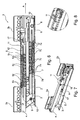
- a rail guide 1 for movable displacement of a relative to a furniture body sliding drawer (not shown) is shown.
- two rail guides are usually provided.
- FIG. 1 is a laterally or below arranged on a drawer rail guide 1 as part of a full extension to Guide the drawer shown.
- a belonging to the rail guide 1 further in the attached state to the longitudinal axis of the drawer mirror image of the rail guide 1 designed rail guide of the full extension is not shown.
- the rail guide 1 comprises telescopically displaceably guided rails, wherein in the installed state a carcass rail 2 with mounting brackets 2a and 2b fixed to a furniture body position and on the carcass rail 2 attachable to the drawer drawer rail 4 and acting between the carcass rail 2 and the drawer rail 4 middle rail. 3 are added slidably.
- a cylinder-piston unit 5 is attached to the drawer rail 4.
- 4 slidably interposed roller carriage 6 and 7 are provided.
- the upper roller carriage 6 with rotatably mounted thereon load-transmitting rollers 6a to 6d is movable between the drawer rail 4 and the middle rail 3 effective.
- a lower roller carriage 7 with rollers 7a to 7d, which are rotatably received on the lower roller carriage 7, is movable between the carcass rail 2 and the center rail 3.
- the rollers 6a to 6d roll on sections of the drawer rail 4 and the center rail 3, or Rollers 7a to 7d roll off at portions of the center rail 3 and the carcass rail 2.
- An embossing can be provided as an elevated portion on a rail, for example on a middle rail, formed portion which in the retracted state of the rails at a mating portion For example, it is seated on the carcass rail and is contact-free when the drawer rail is pushed out.
- a front support roller 8 is provided in the front region of the center rail 3.
- the support roller 8 In the retracted state or in the collapsed state of the rail guide 1, which corresponds to a state of the drawer inserted into the furniture body, the support roller 8 is at the middle rail in ab Planndem contact at a lower located generally horizontally oriented web portion 9 of the carcass rail 2 in contact.
- Run-off slope 10 is formed in the front region of the carcass rail 2 at a front edge of the web section 9 of the carcass rail 2.
- the support roller 8 along the drainage slope 10 until reaching its support position according to FIG. 6 arrive at the web section 9. This is done according to when the drawer is closed or pushed together rail guide 1 FIG. 6 For example, a supporting effect of the center rail 3 on the carcass rail 2.
- the front outer rollers 6a and the front inner rollers 6c and the front outer rollers 7a and the front inner rollers 7c are relieved in the direction of movement forward or in the opening direction of the drawer.
- a remaining load bearing on these rollers 6a, 6c, 7a, 7c remains but usually, especially in size, that all rollers 6a to 6d, 7a to 7d are charged to a comparable extent, but this is not critical with respect to a deformation the rollers 6a, 6c, 7a, 7c.
- none of the rollers in the loading case of the inserted or standing drawer plastically or permanently deformed, for example, partially flattened, which may be the case without support roller 8 at least in the front inner and outer.
- the support roller 8 can in the supporting state according to FIG. 6 possibly. take up a proportion of the load acting without support on the rollers 6a to 6d, 7a to 7d.
- the support roller 8 can, in order not to be deformed if necessary, be configured correspondingly larger diameter and / or harder.
- the support with the support roller 8 at the web section 9 advantageously no lifting of the center rail 3 takes place, or only a slight return upward to a position corresponding to an ideal case with desired distances between the rails 2 and 3, for example unloaded Drawer. Rather, only a compensation of the lowering of the center rail 3 by bending or tilting operations in the inserted state of the drawer takes place, which can not be avoided with appropriate loading of the drawer. This ensures a necessary for optimal motion control between the carcass rail 2 and middle rail 3 on all rollers 7a to 7d of the roller carriage 7 necessary distance between the center rail 3 and cabinet rail 2.
- the support roller 8 acts only supporting in fully collapsed or closed state of the rail guide 1. Once the rail guide 1 and the drawer something from the in FIG. 6 shown inserted position according to arrow A in FIG. 6 is moved forward in the extension direction, the support roller 8 leaves via the drainage slope 10, the contact with the carcass rail 2 after a short distance of eg a few millimeters. The full load transfer when moving the drawer rail or center rail is then carried out on the existing in the roller carriage 6 and 7 rollers 6a and 7a.
- a further or upper support roller 11 is positioned on the drawer rail 4 in the front region and rotatably supported.
- the support roller 11 takes a share of the weight of the drawer and load on and so relieves the rollers 6a to 6d.
- the support with inserted drawer takes place on a front web portion 12 of the center rail 3. This is the top on the center rail 3 usually aligned horizontally, for example, realized by a bent sheet metal portion of the center rail 3.
- FIGS. 3, 4 and 6 It can be seen that at the front end to a horizontal running region of the middle rail 3, a drainage slope 17 is formed, along which the upper support roller 11 on the drawer rail 4 up or can expire.
- the lower roller carriage 7 has front outer rollers 7a, rear outer rollers 7b, front inner rollers 7c and rear inner rollers 7d.
- a reassurance roller 13 is rotatably mounted.
- the example of an elastic material existing reassurance roller 13 is in the fully collapsed state of the rail guide 1 out of contact with the carcass rail 2.
- individual or all rollers may consist of a high-strength material.
- any or all of the rear inner rollers 6d and 7d may be formed of a high strength material.
- a synchronization gear 14 is rotatably mounted on the center rail 3, the meshing in a synchronizing gear 14 matching tooth profile section 15 on the roller carriage 6 and in a tooth profile section 16 on the roller carriage 7 engages.
Landscapes
- Drawers Of Furniture (AREA)
- Telephone Set Structure (AREA)
Claims (11)
- Dispositif comprenant une unité de guidage (1) destinée à guider un tiroir de meuble mobile par rapport à un corps, l'unité de guidage (1) comprenant un rail de corps (2) pouvant être fixé sur le corps, un rail de tiroir (4) pouvant être monté sur le tiroir de meuble et un rail central (3) agissant entre le rail de corps (2) et le rail de tiroir (4), des moyens de support à transmission de charge (6, 6a à 6d, 7, 7a à 7d) étant présents qui permettent le support mobile des rails (2, 3, 4) les uns par rapport aux autres afin de permettre un mouvement de coulissement fiable des rails (2, 3, 4) sur une longueur d'extraction des rails (2, 3, 4), ainsi que des moyens d'appui permettant l'appui du tiroir de meuble dans un état rentré dans le corps, caractérisé en ce que les moyens d'appui comprennent un élément d'appui (8) logé sur le rail central (3) ou sur le rail de tiroir (4), un élément d'appui, vu dans la direction de sortie du tiroir de meuble mobile, étant positionné dans une zone avant du rail (3, 4) respectif, et, pour le cas où un élément d'appui (8) logé sur le rail central (3) est présent pour l'appui du tiroir de meuble dans l'état rentré du tiroir de meuble, cet élément d'appui repose sur le rail de corps (2), et, pour le cas où un élément d'appui logé sur le rail de tiroir est présent, cet élément d'appui repose sur le rail central (3) et, dans un état sorti du tiroir de meuble, aucun soutien n'est mis en oeuvre par un élément d'appui (8).
- Dispositif selon la revendication 1, caractérisé en ce que les moyens de support comprennent un premier corps de base (7) qui est mobile entre le rail de corps (2) et le rail central (3) et sur lequel sont logés des corps de support (7a à 7d) et/ou un deuxième corps de base (6) qui est mobile entre le rail central (3) et le rail de tiroir (4) et sur lequel sont logés des corps de support (6a à 6d), les corps de support (6a à 6d, 7a à 7d) étant nécessaires pour permettre un mouvement coulissant fiable des rails (2, 3, 4) sur une longueur d'extraction des rails (2, 3, 4).
- Dispositif selon l'une des revendications précédentes, caractérisé en ce que les moyens d'appui comprennent un premier élément d'appui (8) qui est logé sur le rail central (3) et qui, vu dans la direction de sortie du tiroir de meuble mobile, est positionné dans une zone avant sur le rail central (3), et qui, pour soutenir le tiroir de meuble dans l'état rentré, repose sur le rail de corps (2), et un deuxième élément d'appui (11) qui est logé, vu dans la direction de sortie du tiroir de meuble mobile, dans une zone avant sur le rail de tiroir (4) et qui, pour soutenir le tiroir de meuble (4) dans l'état rentré, repose sur le rail central (3), aucun appui n'étant mis en oeuvre par le premier élément d'appui (8) et le deuxième élément d'appui (11) dans un état sorti du tiroir de meuble (4).
- Dispositif selon l'une des revendications précédentes, caractérisé en ce que le premier (8) et/ou le deuxième (11) élément d'appui sont adaptés de telle sorte qu'à l'état rentré du tiroir de meuble mobile, il se produit un allégement de charges d'au moins certains des corps de support (6a à 6d, 7a à 7d) à l'aide du premier (8) et/ou du deuxième (11) élément d'appui.
- Dispositif selon l'une des revendications précédentes, caractérisé en ce qu'une surface inclinée (10) est présente sur le rail de corps (2), le long de laquelle l'élément d'appui (8) logé sur le rail central (3) se déplace lorsque le tiroir de meuble mobile effectue un mouvement vers l'état rentré.
- Dispositif selon l'une des revendications précédentes, caractérisé en ce qu'une surface inclinée (17) est présente sur le rail central (3), le long de laquelle l'élément d'appui (11) logé sur le rail de tiroir (4) se déplace lorsque le tiroir de meuble mobile effectue un mouvement vers l'état rentré.
- Dispositif selon l'une des revendications précédentes, caractérisé en ce que le premier (8) et/ou le deuxième (11) élément d'appui sont une roue d'appui logée en rotation sur le rail respectif.
- Dispositif selon l'une des revendications précédentes, caractérisé en ce que le premier (8) et/ou le deuxième (11) élément d'appui peuvent être fixés de manière détachable sur le rail (3, 4) respectif.
- Dispositif selon l'une des revendications précédentes, caractérisé en ce qu'un élément de roulement (13) est prévu sur le rail central (3) dans une zone arrière, vu dans la direction de sortie du tiroir de meuble mobile, en vue d'augmenter le fonctionnement silencieux de l'unité de guidage (1) lorsque le tiroir de meuble effectue un mouvement.
- Dispositif selon l'une des revendications précédentes, caractérisé en ce que l'élément de roulement (13) est logé en rotation sur le rail central (3) et circule sur le rail de corps (2) lorsque le tiroir de meuble effectue un mouvement.
- Meuble comprenant un tiroir de meuble mobile par rapport à un corps, un dispositif selon l'une des revendications précédentes étant présent.
Priority Applications (1)
| Application Number | Priority Date | Filing Date | Title |
|---|---|---|---|
| EP15160205.9A EP2915451B1 (fr) | 2008-12-23 | 2009-12-18 | Dispositif doté d'une unité de guidage pour guider un tiroir de meuble mobile par rapport à un corps et meuble |
Applications Claiming Priority (1)
| Application Number | Priority Date | Filing Date | Title |
|---|---|---|---|
| DE202008017061U DE202008017061U1 (de) | 2008-12-23 | 2008-12-23 | Vorrichtung mit einer Führungseinheit zur Führung eines relativ zu einem Korpus bewegbaren Möbelauszugs und Möbel |
Related Child Applications (2)
| Application Number | Title | Priority Date | Filing Date |
|---|---|---|---|
| EP15160205.9A Division-Into EP2915451B1 (fr) | 2008-12-23 | 2009-12-18 | Dispositif doté d'une unité de guidage pour guider un tiroir de meuble mobile par rapport à un corps et meuble |
| EP15160205.9A Division EP2915451B1 (fr) | 2008-12-23 | 2009-12-18 | Dispositif doté d'une unité de guidage pour guider un tiroir de meuble mobile par rapport à un corps et meuble |
Publications (3)
| Publication Number | Publication Date |
|---|---|
| EP2201864A2 EP2201864A2 (fr) | 2010-06-30 |
| EP2201864A3 EP2201864A3 (fr) | 2012-10-17 |
| EP2201864B1 true EP2201864B1 (fr) | 2016-05-25 |
Family
ID=40530989
Family Applications (2)
| Application Number | Title | Priority Date | Filing Date |
|---|---|---|---|
| EP09015684.5A Not-in-force EP2201864B1 (fr) | 2008-12-23 | 2009-12-18 | Dispositif doté d'une unité de guidage pour guider une sortie de meuble mobile par rapport à un corps et meuble |
| EP15160205.9A Not-in-force EP2915451B1 (fr) | 2008-12-23 | 2009-12-18 | Dispositif doté d'une unité de guidage pour guider un tiroir de meuble mobile par rapport à un corps et meuble |
Family Applications After (1)
| Application Number | Title | Priority Date | Filing Date |
|---|---|---|---|
| EP15160205.9A Not-in-force EP2915451B1 (fr) | 2008-12-23 | 2009-12-18 | Dispositif doté d'une unité de guidage pour guider un tiroir de meuble mobile par rapport à un corps et meuble |
Country Status (4)
| Country | Link |
|---|---|
| EP (2) | EP2201864B1 (fr) |
| CN (1) | CN101953585B (fr) |
| DE (1) | DE202008017061U1 (fr) |
| ES (1) | ES2604986T3 (fr) |
Families Citing this family (9)
| Publication number | Priority date | Publication date | Assignee | Title |
|---|---|---|---|---|
| DE202009003459U1 (de) * | 2009-03-11 | 2010-07-22 | Paul Hettich Gmbh & Co. Kg | Auszugsführung |
| DE102009040752B4 (de) * | 2009-09-10 | 2022-05-12 | Grass Ges.M.B.H. | Vorrichtung zur Führung eines Möbelauszugs, Verfahren zur Herstellung einer Führungseinheit und Möbel |
| DE202010009163U1 (de) * | 2010-06-16 | 2011-12-19 | Grass Gmbh | Führungseinheit sowie Abstützvorrichtung für eine Führungseinheit und Möbel mit einer Führungseinheit |
| DE202011004589U1 (de) | 2011-03-30 | 2012-07-04 | Grass Gmbh | Führungseinrichtung zur Führung eines relativ zu einem Möbelkorpus bewegbaren Möbelauszugs |
| DE202011004588U1 (de) | 2011-03-30 | 2012-07-04 | Grass Gmbh | Führungseinrichtung zur Führung eines relativ zu einem Möbelkorpus bewegbaren Möbelauszugs |
| DE102011122266A1 (de) * | 2011-12-23 | 2013-06-27 | Grass Gmbh | Vorrichtung zur Bewegungsbeeinflussung eines Möbelteils, Führungseinheit zur Bewegungsführung eines Möbelteils und Möbel |
| AT512934B1 (de) * | 2012-11-12 | 2013-12-15 | Blum Gmbh Julius | Schubladenausziehführung |
| AT514810B1 (de) * | 2013-09-23 | 2015-04-15 | Blum Gmbh Julius | Schwimmend gelagerte Abstützrolle |
| DE202020100078U1 (de) * | 2020-01-09 | 2021-04-12 | Grass Gmbh | Stromschiene |
Family Cites Families (9)
| Publication number | Priority date | Publication date | Assignee | Title |
|---|---|---|---|---|
| CH681271A5 (fr) * | 1990-10-01 | 1993-02-26 | Eku Ag | |
| AT404313B (de) * | 1994-10-05 | 1998-10-27 | Fulterer Gmbh | Schubkastenführung für ausziehbare möbelteile |
| AT409710B (de) * | 2000-09-20 | 2002-10-25 | Fulterer Gmbh | Auszug für ein ausziehbares möbelteil |
| CN2642137Y (zh) * | 2003-04-30 | 2004-09-22 | 南俊国际股份有限公司 | 增加使用寿命及可延长伸展长度的抽屉滑轨构造 |
| CN2805508Y (zh) * | 2005-07-05 | 2006-08-16 | 温正看 | 改进的全开复式滑轨结构 |
| AT8732U1 (de) * | 2005-12-06 | 2006-12-15 | Blum Gmbh Julius | Ausziehführungssystem für schubladen |
| DE202006011766U1 (de) * | 2006-07-28 | 2007-11-29 | Alfit Ag | Ausziehführung zur Führung von Möbelteilen |
| US7748801B2 (en) * | 2007-03-14 | 2010-07-06 | Alfit Ag | Telescopic guide for drawers and similar furniture components extendable from a body of furniture |
| AT505053B1 (de) * | 2007-04-02 | 2009-02-15 | Fulterer Gmbh | Rollen-differentialausziehführung |
-
2008
- 2008-12-23 DE DE202008017061U patent/DE202008017061U1/de not_active Expired - Lifetime
-
2009
- 2009-12-18 EP EP09015684.5A patent/EP2201864B1/fr not_active Not-in-force
- 2009-12-18 EP EP15160205.9A patent/EP2915451B1/fr not_active Not-in-force
- 2009-12-18 ES ES15160205.9T patent/ES2604986T3/es active Active
- 2009-12-23 CN CN2009110002549A patent/CN101953585B/zh not_active Expired - Fee Related
Also Published As
| Publication number | Publication date |
|---|---|
| ES2604986T3 (es) | 2017-03-10 |
| CN101953585A (zh) | 2011-01-26 |
| EP2201864A2 (fr) | 2010-06-30 |
| EP2915451A1 (fr) | 2015-09-09 |
| DE202008017061U1 (de) | 2009-04-09 |
| EP2201864A3 (fr) | 2012-10-17 |
| CN101953585B (zh) | 2013-08-21 |
| EP2915451B1 (fr) | 2016-08-24 |
Similar Documents
| Publication | Publication Date | Title |
|---|---|---|
| EP2201864B1 (fr) | Dispositif doté d'une unité de guidage pour guider une sortie de meuble mobile par rapport à un corps et meuble | |
| EP2506738B1 (fr) | Guidage télescopique pour tiroir | |
| EP3727087B1 (fr) | Glissière de sortie de tiroir | |
| EP2992781B1 (fr) | Guidage d'extraction | |
| EP3668350B1 (fr) | Glissière télescopique pour tiroir | |
| EP3096649B1 (fr) | Glissière télescopique de tiroir | |
| EP3092919B2 (fr) | Dispositif de guidage pour le guidage d'une piece de meuble mobile par rapport à un corps de meuble | |
| EP2422650B1 (fr) | Unité de guidage pour un élément de meuble mobile | |
| EP3403529A1 (fr) | Guidage d'extraction | |
| AT516222A1 (de) | Ausziehführung | |
| EP3792512A1 (fr) | Guidage d'extension de tiroir | |
| EP2046164B1 (fr) | Glissière de guidage de parties de meubles | |
| EP4110138B1 (fr) | Guide coulissant | |
| EP2716182B1 (fr) | Guidage d'extraction pour un élément de meuble pouvant être extrait d'un corps de meuble | |
| WO2017070722A1 (fr) | Guidage télescopique pour tiroir | |
| EP2904940B1 (fr) | Dispositif de guidage d'une rallonge et meuble doté d'un tel dispositif | |
| EP3682764B1 (fr) | Dispositif de guidage pour le guidage d'une pièce de meuble mobile par rapport à un corps de meuble |
Legal Events
| Date | Code | Title | Description |
|---|---|---|---|
| PUAI | Public reference made under article 153(3) epc to a published international application that has entered the european phase |
Free format text: ORIGINAL CODE: 0009012 |
|
| AK | Designated contracting states |
Kind code of ref document: A2 Designated state(s): AT BE BG CH CY CZ DE DK EE ES FI FR GB GR HR HU IE IS IT LI LT LU LV MC MK MT NL NO PL PT RO SE SI SK SM TR |
|
| AX | Request for extension of the european patent |
Extension state: AL BA RS |
|
| PUAL | Search report despatched |
Free format text: ORIGINAL CODE: 0009013 |
|
| AK | Designated contracting states |
Kind code of ref document: A3 Designated state(s): AT BE BG CH CY CZ DE DK EE ES FI FR GB GR HR HU IE IS IT LI LT LU LV MC MK MT NL NO PL PT RO SE SI SK SM TR |
|
| AX | Request for extension of the european patent |
Extension state: AL BA RS |
|
| RIC1 | Information provided on ipc code assigned before grant |
Ipc: A47B 88/10 20060101AFI20120913BHEP |
|
| 17P | Request for examination filed |
Effective date: 20130716 |
|
| RBV | Designated contracting states (corrected) |
Designated state(s): AT BE BG CH CY CZ DE DK EE ES FI FR GB GR HR HU IE IS IT LI LT LU LV MC MK MT NL NO PL PT RO SE SI SK SM TR |
|
| 17Q | First examination report despatched |
Effective date: 20141112 |
|
| GRAP | Despatch of communication of intention to grant a patent |
Free format text: ORIGINAL CODE: EPIDOSNIGR1 |
|
| INTG | Intention to grant announced |
Effective date: 20151221 |
|
| GRAS | Grant fee paid |
Free format text: ORIGINAL CODE: EPIDOSNIGR3 |
|
| GRAA | (expected) grant |
Free format text: ORIGINAL CODE: 0009210 |
|
| AK | Designated contracting states |
Kind code of ref document: B1 Designated state(s): AT BE BG CH CY CZ DE DK EE ES FI FR GB GR HR HU IE IS IT LI LT LU LV MC MK MT NL NO PL PT RO SE SI SK SM TR |
|
| REG | Reference to a national code |
Ref country code: GB Ref legal event code: FG4D Free format text: NOT ENGLISH |
|
| REG | Reference to a national code |
Ref country code: CH Ref legal event code: EP |
|
| REG | Reference to a national code |
Ref country code: IE Ref legal event code: FG4D Free format text: LANGUAGE OF EP DOCUMENT: GERMAN Ref country code: AT Ref legal event code: REF Ref document number: 801506 Country of ref document: AT Kind code of ref document: T Effective date: 20160615 |
|
| REG | Reference to a national code |
Ref country code: DE Ref legal event code: R096 Ref document number: 502009012616 Country of ref document: DE |
|
| REG | Reference to a national code |
Ref country code: LT Ref legal event code: MG4D |
|
| REG | Reference to a national code |
Ref country code: NL Ref legal event code: MP Effective date: 20160525 |
|
| PG25 | Lapsed in a contracting state [announced via postgrant information from national office to epo] |
Ref country code: FI Free format text: LAPSE BECAUSE OF FAILURE TO SUBMIT A TRANSLATION OF THE DESCRIPTION OR TO PAY THE FEE WITHIN THE PRESCRIBED TIME-LIMIT Effective date: 20160525 Ref country code: NO Free format text: LAPSE BECAUSE OF FAILURE TO SUBMIT A TRANSLATION OF THE DESCRIPTION OR TO PAY THE FEE WITHIN THE PRESCRIBED TIME-LIMIT Effective date: 20160825 Ref country code: NL Free format text: LAPSE BECAUSE OF FAILURE TO SUBMIT A TRANSLATION OF THE DESCRIPTION OR TO PAY THE FEE WITHIN THE PRESCRIBED TIME-LIMIT Effective date: 20160525 Ref country code: LT Free format text: LAPSE BECAUSE OF FAILURE TO SUBMIT A TRANSLATION OF THE DESCRIPTION OR TO PAY THE FEE WITHIN THE PRESCRIBED TIME-LIMIT Effective date: 20160525 |
|
| REG | Reference to a national code |
Ref country code: DE Ref legal event code: R079 Ref document number: 502009012616 Country of ref document: DE Free format text: PREVIOUS MAIN CLASS: A47B0088100000 Ipc: A47B0088493000 |
|
| PG25 | Lapsed in a contracting state [announced via postgrant information from national office to epo] |
Ref country code: SE Free format text: LAPSE BECAUSE OF FAILURE TO SUBMIT A TRANSLATION OF THE DESCRIPTION OR TO PAY THE FEE WITHIN THE PRESCRIBED TIME-LIMIT Effective date: 20160525 Ref country code: LV Free format text: LAPSE BECAUSE OF FAILURE TO SUBMIT A TRANSLATION OF THE DESCRIPTION OR TO PAY THE FEE WITHIN THE PRESCRIBED TIME-LIMIT Effective date: 20160525 Ref country code: GR Free format text: LAPSE BECAUSE OF FAILURE TO SUBMIT A TRANSLATION OF THE DESCRIPTION OR TO PAY THE FEE WITHIN THE PRESCRIBED TIME-LIMIT Effective date: 20160826 Ref country code: HR Free format text: LAPSE BECAUSE OF FAILURE TO SUBMIT A TRANSLATION OF THE DESCRIPTION OR TO PAY THE FEE WITHIN THE PRESCRIBED TIME-LIMIT Effective date: 20160525 Ref country code: ES Free format text: LAPSE BECAUSE OF FAILURE TO SUBMIT A TRANSLATION OF THE DESCRIPTION OR TO PAY THE FEE WITHIN THE PRESCRIBED TIME-LIMIT Effective date: 20160525 Ref country code: PT Free format text: LAPSE BECAUSE OF FAILURE TO SUBMIT A TRANSLATION OF THE DESCRIPTION OR TO PAY THE FEE WITHIN THE PRESCRIBED TIME-LIMIT Effective date: 20160926 |
|
| PG25 | Lapsed in a contracting state [announced via postgrant information from national office to epo] |
Ref country code: SK Free format text: LAPSE BECAUSE OF FAILURE TO SUBMIT A TRANSLATION OF THE DESCRIPTION OR TO PAY THE FEE WITHIN THE PRESCRIBED TIME-LIMIT Effective date: 20160525 Ref country code: EE Free format text: LAPSE BECAUSE OF FAILURE TO SUBMIT A TRANSLATION OF THE DESCRIPTION OR TO PAY THE FEE WITHIN THE PRESCRIBED TIME-LIMIT Effective date: 20160525 Ref country code: RO Free format text: LAPSE BECAUSE OF FAILURE TO SUBMIT A TRANSLATION OF THE DESCRIPTION OR TO PAY THE FEE WITHIN THE PRESCRIBED TIME-LIMIT Effective date: 20160525 Ref country code: CZ Free format text: LAPSE BECAUSE OF FAILURE TO SUBMIT A TRANSLATION OF THE DESCRIPTION OR TO PAY THE FEE WITHIN THE PRESCRIBED TIME-LIMIT Effective date: 20160525 Ref country code: DK Free format text: LAPSE BECAUSE OF FAILURE TO SUBMIT A TRANSLATION OF THE DESCRIPTION OR TO PAY THE FEE WITHIN THE PRESCRIBED TIME-LIMIT Effective date: 20160525 |
|
| PG25 | Lapsed in a contracting state [announced via postgrant information from national office to epo] |
Ref country code: SM Free format text: LAPSE BECAUSE OF FAILURE TO SUBMIT A TRANSLATION OF THE DESCRIPTION OR TO PAY THE FEE WITHIN THE PRESCRIBED TIME-LIMIT Effective date: 20160525 Ref country code: PL Free format text: LAPSE BECAUSE OF FAILURE TO SUBMIT A TRANSLATION OF THE DESCRIPTION OR TO PAY THE FEE WITHIN THE PRESCRIBED TIME-LIMIT Effective date: 20160525 |
|
| REG | Reference to a national code |
Ref country code: DE Ref legal event code: R097 Ref document number: 502009012616 Country of ref document: DE |
|
| PLBE | No opposition filed within time limit |
Free format text: ORIGINAL CODE: 0009261 |
|
| STAA | Information on the status of an ep patent application or granted ep patent |
Free format text: STATUS: NO OPPOSITION FILED WITHIN TIME LIMIT |
|
| 26N | No opposition filed |
Effective date: 20170228 |
|
| PG25 | Lapsed in a contracting state [announced via postgrant information from national office to epo] |
Ref country code: SI Free format text: LAPSE BECAUSE OF FAILURE TO SUBMIT A TRANSLATION OF THE DESCRIPTION OR TO PAY THE FEE WITHIN THE PRESCRIBED TIME-LIMIT Effective date: 20160525 Ref country code: BE Free format text: LAPSE BECAUSE OF NON-PAYMENT OF DUE FEES Effective date: 20161231 |
|
| REG | Reference to a national code |
Ref country code: CH Ref legal event code: PL |
|
| GBPC | Gb: european patent ceased through non-payment of renewal fee |
Effective date: 20161218 |
|
| PG25 | Lapsed in a contracting state [announced via postgrant information from national office to epo] |
Ref country code: MC Free format text: LAPSE BECAUSE OF FAILURE TO SUBMIT A TRANSLATION OF THE DESCRIPTION OR TO PAY THE FEE WITHIN THE PRESCRIBED TIME-LIMIT Effective date: 20160525 |
|
| REG | Reference to a national code |
Ref country code: FR Ref legal event code: ST Effective date: 20170831 |
|
| REG | Reference to a national code |
Ref country code: IE Ref legal event code: MM4A |
|
| PG25 | Lapsed in a contracting state [announced via postgrant information from national office to epo] |
Ref country code: LU Free format text: LAPSE BECAUSE OF NON-PAYMENT OF DUE FEES Effective date: 20161218 Ref country code: LI Free format text: LAPSE BECAUSE OF NON-PAYMENT OF DUE FEES Effective date: 20161231 Ref country code: FR Free format text: LAPSE BECAUSE OF NON-PAYMENT OF DUE FEES Effective date: 20170102 Ref country code: CH Free format text: LAPSE BECAUSE OF NON-PAYMENT OF DUE FEES Effective date: 20161231 |
|
| PG25 | Lapsed in a contracting state [announced via postgrant information from national office to epo] |
Ref country code: IE Free format text: LAPSE BECAUSE OF NON-PAYMENT OF DUE FEES Effective date: 20161218 Ref country code: GB Free format text: LAPSE BECAUSE OF NON-PAYMENT OF DUE FEES Effective date: 20161218 |
|
| REG | Reference to a national code |
Ref country code: BE Ref legal event code: MM Effective date: 20161231 |
|
| PG25 | Lapsed in a contracting state [announced via postgrant information from national office to epo] |
Ref country code: HU Free format text: LAPSE BECAUSE OF FAILURE TO SUBMIT A TRANSLATION OF THE DESCRIPTION OR TO PAY THE FEE WITHIN THE PRESCRIBED TIME-LIMIT; INVALID AB INITIO Effective date: 20091218 Ref country code: CY Free format text: LAPSE BECAUSE OF FAILURE TO SUBMIT A TRANSLATION OF THE DESCRIPTION OR TO PAY THE FEE WITHIN THE PRESCRIBED TIME-LIMIT Effective date: 20160525 |
|
| PG25 | Lapsed in a contracting state [announced via postgrant information from national office to epo] |
Ref country code: TR Free format text: LAPSE BECAUSE OF FAILURE TO SUBMIT A TRANSLATION OF THE DESCRIPTION OR TO PAY THE FEE WITHIN THE PRESCRIBED TIME-LIMIT Effective date: 20160525 Ref country code: MK Free format text: LAPSE BECAUSE OF FAILURE TO SUBMIT A TRANSLATION OF THE DESCRIPTION OR TO PAY THE FEE WITHIN THE PRESCRIBED TIME-LIMIT Effective date: 20160525 Ref country code: IS Free format text: LAPSE BECAUSE OF FAILURE TO SUBMIT A TRANSLATION OF THE DESCRIPTION OR TO PAY THE FEE WITHIN THE PRESCRIBED TIME-LIMIT Effective date: 20160525 |
|
| PG25 | Lapsed in a contracting state [announced via postgrant information from national office to epo] |
Ref country code: BG Free format text: LAPSE BECAUSE OF FAILURE TO SUBMIT A TRANSLATION OF THE DESCRIPTION OR TO PAY THE FEE WITHIN THE PRESCRIBED TIME-LIMIT Effective date: 20160525 |
|
| PG25 | Lapsed in a contracting state [announced via postgrant information from national office to epo] |
Ref country code: MT Free format text: LAPSE BECAUSE OF FAILURE TO SUBMIT A TRANSLATION OF THE DESCRIPTION OR TO PAY THE FEE WITHIN THE PRESCRIBED TIME-LIMIT Effective date: 20160525 |
|
| PGFP | Annual fee paid to national office [announced via postgrant information from national office to epo] |
Ref country code: IT Payment date: 20221205 Year of fee payment: 14 Ref country code: DE Payment date: 20221205 Year of fee payment: 14 Ref country code: AT Payment date: 20221206 Year of fee payment: 14 |
|
| REG | Reference to a national code |
Ref country code: DE Ref legal event code: R119 Ref document number: 502009012616 Country of ref document: DE |
|
| REG | Reference to a national code |
Ref country code: AT Ref legal event code: MM01 Ref document number: 801506 Country of ref document: AT Kind code of ref document: T Effective date: 20231218 |
|
| PG25 | Lapsed in a contracting state [announced via postgrant information from national office to epo] |
Ref country code: DE Free format text: LAPSE BECAUSE OF NON-PAYMENT OF DUE FEES Effective date: 20240702 |
|
| PG25 | Lapsed in a contracting state [announced via postgrant information from national office to epo] |
Ref country code: AT Free format text: LAPSE BECAUSE OF NON-PAYMENT OF DUE FEES Effective date: 20231218 |
|
| PG25 | Lapsed in a contracting state [announced via postgrant information from national office to epo] |
Ref country code: DE Free format text: LAPSE BECAUSE OF NON-PAYMENT OF DUE FEES Effective date: 20240702 Ref country code: AT Free format text: LAPSE BECAUSE OF NON-PAYMENT OF DUE FEES Effective date: 20231218 |
|
| PG25 | Lapsed in a contracting state [announced via postgrant information from national office to epo] |
Ref country code: IT Free format text: LAPSE BECAUSE OF NON-PAYMENT OF DUE FEES Effective date: 20231218 |