EP2204495A2 - Haltevorrichtung für leichte und schwere Fahrzeuge auf einem Verkehrsweg - Google Patents
Haltevorrichtung für leichte und schwere Fahrzeuge auf einem Verkehrsweg Download PDFInfo
- Publication number
- EP2204495A2 EP2204495A2 EP09306334A EP09306334A EP2204495A2 EP 2204495 A2 EP2204495 A2 EP 2204495A2 EP 09306334 A EP09306334 A EP 09306334A EP 09306334 A EP09306334 A EP 09306334A EP 2204495 A2 EP2204495 A2 EP 2204495A2
- Authority
- EP
- European Patent Office
- Prior art keywords
- rod
- retaining elements
- rods
- longitudinal
- post
- Prior art date
- Legal status (The legal status is an assumption and is not a legal conclusion. Google has not performed a legal analysis and makes no representation as to the accuracy of the status listed.)
- Withdrawn
Links
- 230000004888 barrier function Effects 0.000 claims abstract description 30
- 239000002184 metal Substances 0.000 claims abstract description 16
- 230000000694 effects Effects 0.000 claims abstract description 6
- 125000006850 spacer group Chemical group 0.000 claims description 14
- 230000014759 maintenance of location Effects 0.000 claims description 3
- 230000037431 insertion Effects 0.000 claims 1
- 238000003780 insertion Methods 0.000 claims 1
- XLYOFNOQVPJJNP-UHFFFAOYSA-N water Substances O XLYOFNOQVPJJNP-UHFFFAOYSA-N 0.000 claims 1
- 230000035939 shock Effects 0.000 description 8
- 238000005452 bending Methods 0.000 description 2
- 230000008878 coupling Effects 0.000 description 2
- 238000010168 coupling process Methods 0.000 description 2
- 238000005859 coupling reaction Methods 0.000 description 2
- 229910001335 Galvanized steel Inorganic materials 0.000 description 1
- 238000010276 construction Methods 0.000 description 1
- 239000008397 galvanized steel Substances 0.000 description 1
- 238000009434 installation Methods 0.000 description 1
- 238000012423 maintenance Methods 0.000 description 1
- 238000004519 manufacturing process Methods 0.000 description 1
- 238000009418 renovation Methods 0.000 description 1
- 230000000452 restraining effect Effects 0.000 description 1
- 238000003466 welding Methods 0.000 description 1
- 239000002023 wood Substances 0.000 description 1
Images

Classifications
-
- E—FIXED CONSTRUCTIONS
- E01—CONSTRUCTION OF ROADS, RAILWAYS, OR BRIDGES
- E01F—ADDITIONAL WORK, SUCH AS EQUIPPING ROADS OR THE CONSTRUCTION OF PLATFORMS, HELICOPTER LANDING STAGES, SIGNS, SNOW FENCES, OR THE LIKE
- E01F15/00—Safety arrangements for slowing, redirecting or stopping errant vehicles, e.g. guard posts or bollards; Arrangements for reducing damage to roadside structures due to vehicular impact
- E01F15/02—Continuous barriers extending along roads or between traffic lanes
- E01F15/04—Continuous barriers extending along roads or between traffic lanes essentially made of longitudinal beams or rigid strips supported above ground at spaced points
- E01F15/0407—Metal rails
- E01F15/0423—Details of rails
- E01F15/043—Details of rails with multiple superimposed members; Rails provided with skirts
-
- E—FIXED CONSTRUCTIONS
- E01—CONSTRUCTION OF ROADS, RAILWAYS, OR BRIDGES
- E01F—ADDITIONAL WORK, SUCH AS EQUIPPING ROADS OR THE CONSTRUCTION OF PLATFORMS, HELICOPTER LANDING STAGES, SIGNS, SNOW FENCES, OR THE LIKE
- E01F15/00—Safety arrangements for slowing, redirecting or stopping errant vehicles, e.g. guard posts or bollards; Arrangements for reducing damage to roadside structures due to vehicular impact
- E01F15/02—Continuous barriers extending along roads or between traffic lanes
- E01F15/025—Combinations of at least two of the barrier member types covered by E01F15/04 - E01F15/08, e.g. rolled steel section or plastic strip backed up by cable, safety kerb topped by rail barrier
-
- E—FIXED CONSTRUCTIONS
- E01—CONSTRUCTION OF ROADS, RAILWAYS, OR BRIDGES
- E01F—ADDITIONAL WORK, SUCH AS EQUIPPING ROADS OR THE CONSTRUCTION OF PLATFORMS, HELICOPTER LANDING STAGES, SIGNS, SNOW FENCES, OR THE LIKE
- E01F15/00—Safety arrangements for slowing, redirecting or stopping errant vehicles, e.g. guard posts or bollards; Arrangements for reducing damage to roadside structures due to vehicular impact
- E01F15/02—Continuous barriers extending along roads or between traffic lanes
- E01F15/04—Continuous barriers extending along roads or between traffic lanes essentially made of longitudinal beams or rigid strips supported above ground at spaced points
- E01F15/0461—Supports, e.g. posts
Definitions
- the present invention relates to a device for retaining light and heavy vehicles along a taxiway. It has applications in the field of Civil Engineering and in particular the construction, maintenance or renovation of traffic lanes. It can, in particular, be implemented on an existing safety barrier to increase its restraining efficiency of both light and heavy vehicles.
- a vehicle restraint device which comprises in the lower part a safety barrier to smooth and in the upper part an upper rail attached to the safety barrier.
- the safety barrier comprises vertical hollow posts anchored in the ground and spacers bolted to the upper part of the posts, the low longitudinal rails, being fixed on the spacers, and the posts being metal profiles in C.
- the upper rails are held above the safety barrier by bent rods introduced into the posts. Maintaining the upper rails on the rods is effected by fusible hooking (keying) and in case of impact, the high smooth (s) and the / rods separate.
- the rods that are introduced into the posts can slide there especially in case of impact with a vehicle.
- the contoured rod which is an omega section is difficult to achieve in a simple manner and requires cutting and welding to achieve the planned angulations.
- the rod must be very rigid so that the fusible coupling can work in case of shock.
- the rod will follow the movement of the safety barrier which bends and this rod thus forms an extension of the barrier which increases the width of the 'grip, also called deformation pocket, the device which bends backwards, besides said rod has been able to slide in the post, which further increases this grip.
- the possible influence of the device after a shock is an important element to take into account during its installation and / or for compliance with standards.
- the present invention proposes to remedy in particular the drawbacks mentioned with a light and heavy vehicle restraint device along a taxiway, the device comprising in the lower part a safety barrier at the rails and at the top a high retaining means mounted on the safety barrier, the safety barrier comprising vertical hollow posts anchored in the ground and spacers bolted to the upper part of the posts, the longitudinal rails being fixed to the spacers, the posts being C-shaped metal sections, high retaining means comprising rods on which are fixed by fixing means longitudinal retaining elements, the rods being introduced into the posts and slidable there particularly in case of impact with a vehicle.
- the longitudinal retaining elements are fixed rigidly upwards of the rods in such a way that, in the event of impact with a vehicle, the rods remain integral with the retaining elements and the rod is a straight C-shaped metal section of which the resistance is such that in case of impact with a vehicle, the rod can bend under the action, on the one hand, down the rod, the folding of the pole of the security barrier leading to the rear and the floor and, on the other hand, towards the top of the rod, the longitudinal pulling effect of the longitudinal retaining elements tending to maintain said longitudinal retaining elements at their initial position, said folding of the rod and said fixing the rod allowing the final deformation front-rear (the front is on the side of the traffic lane and vehicles and the rear is the opposite to the device) of the restraint device in case of shock matches substantially u bending the post of the security fence.
- FR 2 866 662 A1 in which a rigid rod bypassed and a fuse coupling between the upper arm and the rod are implemented, in case of impact, the rod disengages from the upper arm and undergoes substantially no bending. It follows that the stem of FR 2 866 662 A1 , always slipped into the post bent backwards, extends backward this one by realizing a rearward grip of the device much larger than in the case of the present invention.
- the light and heavy vehicle restraint device 1 along a taxiway consists of two parts.
- the safety barrier 2 comprises on the Figure 1 , a hollow post 5, typically of C100 metal profile, driven into the ground 4, a spacer 6 typically metallic and the smooth 7 typically metal double corrugation.
- the spacer 6 is fixed to the post by bolting 11 and a height adjustment of the rail 7 + spacer 6 relative to the ground 4 is performed during tightening.
- the posts are placed every 2 m approximately along the length of the device.
- the retaining means 3 comprises on the Figure 1 a straight rod 8 with at its upper part a longitudinal retaining element 9 fixed thereto rigidly by a fixing means 10 comprising a stirrup.
- a fixing means 10 comprising a stirrup.
- the fixation of the retaining element on the rod is here not fusible but, on the contrary, is rigid and must resist during an impact, that is to say that the retaining element and the rod must remain in solidarity during a shock.
- the rod 8, rectilinear, which is a metal profile typically C80 is inserted into the pole 5.
- the rod 8 is made by folding a sheet.
- the post and the rod are C-sections, they are in inverse position relative to each other so that the rod can pass beyond the bolting of the spreader + smooth on the pole .
- a stop or locking tab 12 is made in the rod 8 at a certain distance from its lower end to block the descent of the rod 8 in the pole 5, the stop 12 abuts against the bolting 11. Because the distance between the stop 12 and the mounting of the fixing means 10 on the rod 8 is predetermined, the correct height arrangement of the retaining element 9 relative to the ground is driven by the correct arrangement of the rail 7 relative to the ground.
- the rail 7 and the retaining element 9 are placed at heights such that they are respectively adapted to a light vehicle (thanks to the rail which is downwards from the device) and a heavy vehicle (thanks to the holding element which is upwardly of the device).
- the rails are about 70 cm above the ground or the road and the retaining elements about 1 m to 1.10 m above the ground or roadway.
- the retaining element 9 is further back than the smooth 7. It may be noted that the lower end of the rod does not go down to the ground / pavement level in the post. We will see Figure 2 this prevents the stem from being stuck in the post during an impact because the post tends to bend at ground level.
- the safety barrier 2 may be de novo installed during the production of the device 1 of the invention or it is possible to use a safety barrier already in place to reinforce it by combining the retaining means 3.
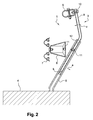
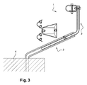
- the device of the invention is shocked by a vehicle and deforms.
- the fence post is bent back and the ground (arrow a).
- the retaining element by lateral pulling effect, tends to remain at its initial position or, at least, to move slightly, and, therefore, besides that the rod can slide in the post (arrow b ), there is a folding of the rod (arrow c) because the latter remains integral with the retaining element.
- the retaining elements 9 In order to be able to remain substantially in place or, at the very least, to move slightly, in the event of impact, the retaining elements 9 must be secured to each other in a longitudinally resistant manner, along the device, so that the side pulling effect by the posts and rods placed on either side of the point of collision of the vehicle on the device and which do not directly suffer the shock, laterally hold said retaining elements. Thanks to the fact that the rod 8 can deform relatively easily in the event of impact and that the retaining element 9 does not separate from the rod 8, the deformation pocket thus remains limited. During the shock, the beam 7 and the spacer 6 are detached from the post because of the failure of the bolting 11. In other cases, the arm and the spacer can remain secured to the post.
- Figures 2 and 3 are schematic because, in practice, other elements of the device can undergo deformations during an impact, including the retractor or the smooth, but to simplify the explanations only major deformations have been represented.
- the device Due to its dynamic behavior in the event of impact, the device can meet the requirements of the standards relating to vehicle restraint systems.
- the device of the invention makes it possible to retain both light vehicles and heavy vehicles.
- the retaining element instead of being a single-wave rail with inwardly curved edges, may be a profile of any other suitable shape and, for example, a double-wave rail such as that of the barrier.
- the rod may have a shape other than C and its thickness to be adapted to the shape in question to be deformed in case of impact.
- all the parts of the device are metallic, hot-dip galvanized steel for example, in some variants of them can be made of wood such as for example in replacement of the metal bottom of the bottom, that of the barrier of security.
Landscapes
- Engineering & Computer Science (AREA)
- Architecture (AREA)
- Civil Engineering (AREA)
- Structural Engineering (AREA)
- Refuge Islands, Traffic Blockers, Or Guard Fence (AREA)
Applications Claiming Priority (1)
| Application Number | Priority Date | Filing Date | Title |
|---|---|---|---|
| FR0859164A FR2940660A1 (fr) | 2008-12-31 | 2008-12-31 | Dispositif de retenue de vehicules leger et lourd le long d'une voie de circulation |
Publications (2)
| Publication Number | Publication Date |
|---|---|
| EP2204495A2 true EP2204495A2 (de) | 2010-07-07 |
| EP2204495A3 EP2204495A3 (de) | 2012-08-29 |
Family
ID=40912102
Family Applications (1)
| Application Number | Title | Priority Date | Filing Date |
|---|---|---|---|
| EP09306334A Withdrawn EP2204495A3 (de) | 2008-12-31 | 2009-12-29 | Haltevorrichtung für leichte und schwere Fahrzeuge auf einem Verkehrsweg |
Country Status (2)
| Country | Link |
|---|---|
| EP (1) | EP2204495A3 (de) |
| FR (1) | FR2940660A1 (de) |
Cited By (5)
| Publication number | Priority date | Publication date | Assignee | Title |
|---|---|---|---|---|
| WO2014207473A1 (en) * | 2013-06-28 | 2014-12-31 | Hill & Smith Limited | Road safety barrier |
| US20150129822A1 (en) * | 2013-10-11 | 2015-05-14 | Safe Direction Pty Ltd | Barrier system |
| CN107130544A (zh) * | 2016-02-29 | 2017-09-05 | 贵州华佑金属制品有限公司 | 公路护栏 |
| GB2639282A (en) * | 2024-03-11 | 2025-09-17 | Tata Steel Uk Ltd | A crash barrier, method of production and method of installation thereof |
| WO2025191261A1 (en) * | 2024-03-11 | 2025-09-18 | Tata Steel Uk Limited | A crash barrier, method of production and method of installation thereof |
Citations (2)
| Publication number | Priority date | Publication date | Assignee | Title |
|---|---|---|---|---|
| FR2564498A1 (fr) | 1984-05-21 | 1985-11-22 | Routier Equip Sa | Dispositif de retenue pour voies de circulation routiere |
| FR2866662A1 (fr) | 2004-02-23 | 2005-08-26 | Profil R | Dispositif de retenue pour glissiere de securite |
Family Cites Families (1)
| Publication number | Priority date | Publication date | Assignee | Title |
|---|---|---|---|---|
| IT1257376B (it) * | 1992-02-04 | 1996-01-15 | Acciai Centro Spa | Barriera stradale semirigida a dissipazione controllata dell'energia d'urto con correzione d'assetto. |
-
2008
- 2008-12-31 FR FR0859164A patent/FR2940660A1/fr not_active Withdrawn
-
2009
- 2009-12-29 EP EP09306334A patent/EP2204495A3/de not_active Withdrawn
Patent Citations (2)
| Publication number | Priority date | Publication date | Assignee | Title |
|---|---|---|---|---|
| FR2564498A1 (fr) | 1984-05-21 | 1985-11-22 | Routier Equip Sa | Dispositif de retenue pour voies de circulation routiere |
| FR2866662A1 (fr) | 2004-02-23 | 2005-08-26 | Profil R | Dispositif de retenue pour glissiere de securite |
Cited By (8)
| Publication number | Priority date | Publication date | Assignee | Title |
|---|---|---|---|---|
| WO2014207473A1 (en) * | 2013-06-28 | 2014-12-31 | Hill & Smith Limited | Road safety barrier |
| GB2515910A (en) * | 2013-06-28 | 2015-01-07 | Hill & Smith Ltd | Road safety barrier |
| GB2515910B (en) * | 2013-06-28 | 2020-05-27 | Hill & Smith Ltd | Road safety barrier |
| US20150129822A1 (en) * | 2013-10-11 | 2015-05-14 | Safe Direction Pty Ltd | Barrier system |
| US9217230B2 (en) * | 2013-10-11 | 2015-12-22 | Safe Direction Pty Ltd | Barrier system |
| CN107130544A (zh) * | 2016-02-29 | 2017-09-05 | 贵州华佑金属制品有限公司 | 公路护栏 |
| GB2639282A (en) * | 2024-03-11 | 2025-09-17 | Tata Steel Uk Ltd | A crash barrier, method of production and method of installation thereof |
| WO2025191261A1 (en) * | 2024-03-11 | 2025-09-18 | Tata Steel Uk Limited | A crash barrier, method of production and method of installation thereof |
Also Published As
| Publication number | Publication date |
|---|---|
| FR2940660A1 (fr) | 2010-07-02 |
| EP2204495A3 (de) | 2012-08-29 |
Similar Documents
| Publication | Publication Date | Title |
|---|---|---|
| EP2204495A2 (de) | Haltevorrichtung für leichte und schwere Fahrzeuge auf einem Verkehrsweg | |
| EP1884416A1 (de) | Blockrahmen vor Kraftfahrzeugen | |
| EP3027487B1 (de) | Stossdämpfender vorrichtung für kraftfahrzeug | |
| EP2504493A1 (de) | Ablenkschirm für steine | |
| CA2768945C (fr) | Dispositif de liaison pour un ouvrage en sol renforce, ouvrage et procede associes | |
| EP1391558B1 (de) | Strassenleitplanke mit verformbaren Abstandshaltern | |
| EP3746349B1 (de) | Fahrzeugstruktur mit einem vorderen säulenverstärkungsteil und einer seitenschiene | |
| FR3071856B1 (fr) | Barriere anti voiture belier | |
| FR2752255A1 (fr) | Bouclier de dispositif de retenue lateral metallique pour la securite des motocyclistes | |
| FR3094328A1 (fr) | Vehicule avec renfort au niveau du passage de roue avant | |
| FR2971529A1 (fr) | Garde-corps | |
| EP1260948A1 (de) | Befestigungsvorrichtung zur Sicherung von Bankautomaten und Geldausgabeautomaten gegen Ausreissgefahr | |
| EP3055191B1 (de) | Kraftfahrzeug mit bügel zum verformen einer der seitenleisten bei einem frontalaufprall | |
| FR3056507A1 (fr) | Vehicule comprenant un dispositif d’absorption de chocs | |
| FR3038574A1 (fr) | Structure de vehicule comportant un element de renfort et vehicule comportant une telle structure | |
| FR2906544A1 (fr) | Agencement formant barriere de securite | |
| FR2770236A1 (fr) | Glissiere de securite routiere comportant une lisse nervuree en bois renforcee par une lame d'acier et un ecarteur la reliant a un support | |
| FR2842557A1 (fr) | Cloture metallique dont les plis des poteaux bloquent lateralement les bouts aplatis des fils horizontaux des panneaux en grillage soude | |
| FR2607841A1 (fr) | Glissiere de securite routiere | |
| FR2714406A1 (fr) | Elément-poutre préfabriqué pour la formation d'une barrière de sécurité pour voie de circulation routière et barrière obtenue. | |
| FR2890399A1 (fr) | Structure d'elargissement d'une route | |
| FR2935401A1 (fr) | Systeme de retenue de vehicule automobile | |
| FR2940339A1 (fr) | Cloture en panneaux grillages maintenus par des poteaux supports associes a des clips de verrouillage | |
| FR2811344A1 (fr) | Glissiere de securite routiere en bois avec renfort metal continu insere dans le rondin | |
| EP2666934A1 (de) | Verfahren zur Erhöhung eines bestehenden Zauns, Überhöhungspfosten und so erhöhter Zaunpfosten |
Legal Events
| Date | Code | Title | Description |
|---|---|---|---|
| PUAI | Public reference made under article 153(3) epc to a published international application that has entered the european phase |
Free format text: ORIGINAL CODE: 0009012 |
|
| AK | Designated contracting states |
Kind code of ref document: A2 Designated state(s): AT BE BG CH CY CZ DE DK EE ES FI FR GB GR HR HU IE IS IT LI LT LU LV MC MK MT NL NO PL PT RO SE SI SK SM TR |
|
| AX | Request for extension of the european patent |
Extension state: AL BA RS |
|
| PUAL | Search report despatched |
Free format text: ORIGINAL CODE: 0009013 |
|
| AK | Designated contracting states |
Kind code of ref document: A3 Designated state(s): AT BE BG CH CY CZ DE DK EE ES FI FR GB GR HR HU IE IS IT LI LT LU LV MC MK MT NL NO PL PT RO SE SI SK SM TR |
|
| AX | Request for extension of the european patent |
Extension state: AL BA RS |
|
| RIC1 | Information provided on ipc code assigned before grant |
Ipc: E01F 15/04 20060101AFI20120720BHEP |
|
| STAA | Information on the status of an ep patent application or granted ep patent |
Free format text: STATUS: THE APPLICATION IS DEEMED TO BE WITHDRAWN |
|
| 18D | Application deemed to be withdrawn |
Effective date: 20130301 |