EP2208401B1 - Ballast électronique et procédé pour faire fonctionner au moins une première et une deuxième lampes à décharge - Google Patents
Ballast électronique et procédé pour faire fonctionner au moins une première et une deuxième lampes à décharge Download PDFInfo
- Publication number
- EP2208401B1 EP2208401B1 EP07822414A EP07822414A EP2208401B1 EP 2208401 B1 EP2208401 B1 EP 2208401B1 EP 07822414 A EP07822414 A EP 07822414A EP 07822414 A EP07822414 A EP 07822414A EP 2208401 B1 EP2208401 B1 EP 2208401B1
- Authority
- EP
- European Patent Office
- Prior art keywords
- threshold value
- electronic switch
- discharge lamp
- inductance
- designed
- Prior art date
- Legal status (The legal status is an assumption and is not a legal conclusion. Google has not performed a legal analysis and makes no representation as to the accuracy of the status listed.)
- Not-in-force
Links
- 238000000034 method Methods 0.000 title claims description 10
- 238000001514 detection method Methods 0.000 claims abstract description 21
- 238000005259 measurement Methods 0.000 claims description 7
- 230000002596 correlated effect Effects 0.000 claims description 5
- 239000003990 capacitor Substances 0.000 description 6
- 238000012935 Averaging Methods 0.000 description 1
- 238000013459 approach Methods 0.000 description 1
- 238000012937 correction Methods 0.000 description 1
- 230000008878 coupling Effects 0.000 description 1
- 238000010168 coupling process Methods 0.000 description 1
- 238000005859 coupling reaction Methods 0.000 description 1
- 230000001419 dependent effect Effects 0.000 description 1
- 238000011156 evaluation Methods 0.000 description 1
- 238000012544 monitoring process Methods 0.000 description 1
- 230000001960 triggered effect Effects 0.000 description 1
Images
Classifications
-
- H—ELECTRICITY
- H05—ELECTRIC TECHNIQUES NOT OTHERWISE PROVIDED FOR
- H05B—ELECTRIC HEATING; ELECTRIC LIGHT SOURCES NOT OTHERWISE PROVIDED FOR; CIRCUIT ARRANGEMENTS FOR ELECTRIC LIGHT SOURCES, IN GENERAL
- H05B41/00—Circuit arrangements or apparatus for igniting or operating discharge lamps
- H05B41/14—Circuit arrangements
- H05B41/26—Circuit arrangements in which the lamp is fed by power derived from DC by means of a converter, e.g. by high-voltage DC
- H05B41/28—Circuit arrangements in which the lamp is fed by power derived from DC by means of a converter, e.g. by high-voltage DC using static converters
- H05B41/282—Circuit arrangements in which the lamp is fed by power derived from DC by means of a converter, e.g. by high-voltage DC using static converters with semiconductor devices
- H05B41/285—Arrangements for protecting lamps or circuits against abnormal operating conditions
- H05B41/2851—Arrangements for protecting lamps or circuits against abnormal operating conditions for protecting the circuit against abnormal operating conditions
- H05B41/2856—Arrangements for protecting lamps or circuits against abnormal operating conditions for protecting the circuit against abnormal operating conditions against internal abnormal circuit conditions
-
- H—ELECTRICITY
- H05—ELECTRIC TECHNIQUES NOT OTHERWISE PROVIDED FOR
- H05B—ELECTRIC HEATING; ELECTRIC LIGHT SOURCES NOT OTHERWISE PROVIDED FOR; CIRCUIT ARRANGEMENTS FOR ELECTRIC LIGHT SOURCES, IN GENERAL
- H05B41/00—Circuit arrangements or apparatus for igniting or operating discharge lamps
- H05B41/14—Circuit arrangements
- H05B41/36—Controlling
- H05B41/38—Controlling the intensity of light
- H05B41/382—Controlling the intensity of light during the transitional start-up phase
Definitions
- the present invention relates to an electronic ballast for operating at least a first and a second discharge lamp with a bridge circuit comprising at least a first and a second electronic switch, wherein the input of the bridge circuit is coupled to a DC supply voltage, wherein the output of the bridge circuit with a first terminal for a first discharge lamp and a second terminal for a second discharge lamp, wherein the first and second terminals are connected in parallel with respect to the output of the bridge circuit, at least one first and one second ignitors, one in series with the other Discharge lamp arranged inductance and arranged parallel to the respective discharge lamp capacitance comprises, a current measuring device which is designed to provide at its output a signal with the actual value of the total current through the least ns first and second inductance is correlated, and a drive circuit.
- the latter has at least a first and a second output for driving at least the first and the second electronic switch, a first input, which is coupled to the output of the current measuring device, a Schwellwertvorgabevorraum for specifying at least a first threshold value for the total current through at least the first and the second inductance, wherein the drive circuit designed is to control at least the first and the second electronic switch, taking into account the first SChwellwerts as a setpoint. It also relates to a method for operating at least a first and a second discharge lamp on such an electronic ballast.
- the present invention relates in particular to the problem that high and low pressure discharge lamps for ignition require high voltages. These voltages are generated by electronic ballasts using a series resonant circuit. In two- or multi-lamp electronic ballasts often two or more parallel load circuits are used. In the case of two-lamp electronic ballasts, by means of which the following invention is described by way of example, therefore, the bridge circuit must be designed for twice the current as in the operation of a single discharge lamp. Usually, both load circuits do not have exactly the same resonant frequency. This can cause one discharge lamp to fire earlier than the other. If this happens, the current in the load circuit with the ignited discharge lamp becomes significantly smaller.
- an ignition controller provided in the electronic ballast still allows twice the current compared to the ignition of a discharge lamp, this current then being largely due to the unloaded, ignited load circuit. flows. As a result, significantly higher ignition voltages are generated in this open circuit than desired.
- the present invention is therefore the object of developing an aforementioned electronic ballast or an aforementioned method such that a dimensioning of the components involved for lower voltages is possible.
- the present invention is based on the finding that this object can be achieved if the electronic ballast further comprises an ignition detection device for detecting whether one of the discharge lamps has ignited.
- the drive circuit comprises a second input which is coupled to the ignition detection device, wherein the threshold value setting device is further designed to specify a second threshold value for the setpoint value of the total current through at least the first and the second inductance, wherein the second threshold value is smaller in magnitude than the first one threshold.
- the drive circuit is configured to drive at least the first and second switches before detecting the ignition of a discharge lamp by the ignition detection device as the target value after detecting the ignition of a discharge lamp by the ignition detection device in consideration of the second threshold value.
- a preferred embodiment is characterized in that the drive circuit further comprises a comparator which is designed to compare the actual value of the total current through at least the first and the second inductance with the respective desired value of this current.
- a comparator for example, the microcontroller AT90PWM2 the company Atmel can be used. By using a comparator, compliance with the setpoint can be monitored very closely. This makes it possible to realize a precise, cost-effective dimensioning of the components involved.
- the ignition detection device comprises a power measurement device configured to determine a magnitude correlated with the power output at the at least first and second ports.
- the measurement of power provides a more reliable indication of whether one of the involved lamps has ignited or not.
- the drive circuit is designed, the actual value of the total current by varying the frequency of the signal, with which at least the first and the second electronic. Switches are controlled to regulate.
- the drive circuit is furthermore preferably designed to control the frequency of the signal with which at least the first and the second electronic switches are actuated be further lowered after detecting the ignition of a discharge lamp. This procedure is described in the applications ⁇ WO 2008/037290 A1 and EP1871147 A1 ,
- the drive circuit of an electronic ballast according to the invention is in particular designed so that a changeover from the first to the second threshold value in a period of time which is a maximum of 1 ms, preferably a maximum of 200 ⁇ s, can be made.
- the wording "taking into account the first or second threshold” takes into account the fact that in practice a slight exceeding of the respective threshold value may occur, since only the current through the lower electronic switch when the bridge circuit is implemented by a half bridge is evaluated for the current measurement becomes.
- the second threshold value is at most 80%, preferably at most 75% of the first threshold value.
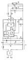
- Fig. 1 shows a schematic representation of the structure of an electronic ballast according to the invention for operating a first La1 and a second discharge lamp La2.
- the ballast comprises a first E1 and a second terminal E2 for connection to a mains voltage U N.
- a block 10 which includes a rectifier and components for EMC protection.
- a boost converter 12 which comprises an inductance L1, a switch S1, a diode D1 and a capacitor C1.
- the so-called intermediate circuit voltage U zw is provided on the one hand to a voltage divider R1, R2, on the other hand to the two switches S2, S3 of a half-bridge.
- the signal picked up at the resistor R2 is supplied to a unit 14 of a microcontroller 16, the unit 14 serving for PFC (Power Factor Correction).
- the switch S1 of the boost converter 12 is actuated in a manner known to the person skilled in the art with regard to the magnitude of the voltage U zw sensed by the resistor R2.
- the switches S2, S3 of the half-bridge are controlled via a drive generator 18 of the microcontroller 16.
- the half-bridge center HB is coupled via a coupling capacitor C2 to a first and a second load circuit.
- the first load circuit comprises the already mentioned lamp La1 and a series resonant circuit comprising an inductance L2 and a capacitor C3.
- the second load circuit comprises the lamp La2 and a series resonant circuit comprising an inductor L3 and a capacitor C4.
- a shunt resistor R3 is used to measure the current through the lower switch S3 of the half-bridge. For this purpose, the voltage drop across the resistor R3 is transmitted via an ohmic resistor R4 and a capacitor C4, which serve to averaging, to a device 20 for power measurement. It is used to determine the performance in addition to the current, the known intermediate circuit voltage U zw taken into account.
- the device 20 for power measurement is coupled on the output side to a control circuit 22, which fulfills two functions. It comprises a threshold value setting device which predefines a threshold value for the set value of the total current through the first L2 and the second inductance L3. This threshold value varies with regard to whether neither of the two lamps La1, La2 has yet ignited or whether one of the two lamps La1, La2 has already ignited. In the event that one of the lamps La1, La2 has already ignited, the threshold value predefined by the control circuit 22 is significantly smaller than in the case in which neither of the two lamps La1, La2 has yet fired.
- the respective setpoint value specified threshold value is compared with the current actual value in a comparator 24 of the microcontroller 22.
- the control circuit 22 also serves to predefine the drive generator 18 with a frequency with which the switches S2, S3 of the bridge circuit are to be controlled.
- the control circuit 22 is in particular designed to further lower the frequency of the signal with which the switches S2, S3 are actuated, after detection of the ignition of one of the discharge lamps La1, La2.
- the drive generator 18 controls the switches S2, S3 starting with a start frequency. This is gradually lowered, wherein continuously compared via the comparator 24 of the measured via the shunt resistor R3 current to a first threshold becomes. If this threshold value is reached, the ignition process is aborted and started again at the starting frequency. If, however, the lowering of the frequency leads to the ignition of one of the two discharge lamps La1, La2, this is detected by the device 20 for power measurement, whereupon the control circuit 22 provides the comparator 24 with an absolute smaller threshold value. If a further lowering of the frequency with which the drive generator 18 applies the switches S2, S3 to ignite the second discharge lamp, the ignition process is ended. If, however, the lowering of the frequency does not lead to the ignition of the second discharge lamp, the frequency is lowered until the comparator 24 determines that the second, smaller magnitude threshold has been reached.
- the electronic ballast switches off.
- a network reset can be used to start a new ignition attempt.
Landscapes
- Circuit Arrangements For Discharge Lamps (AREA)
Claims (8)
- Ballast électronique pour faire fonctionner au moins une première lampe ( La1 ) à décharge et une deuxième lampe ( La2 ) à décharge, comprenant- un circuit ( S2, S3 ) en pont qui comprend au moins un premier interrupteur ( S2 ) électronique et un deuxième interrupteur ( S3 ) électronique, une tension ( Uzw ) continue d'alimentation étant appliquée à l'entrée du circuit ( S2, S3 ) en pont, la sortie du circuit ( S2, S3 ) en pont étant reliée à une première borne pour une première lampe ( La1 ) à décharge et à une deuxième borne pour une deuxième lampe ( La2 ) à décharge, la première et la deuxième borne étant montées en parallèle par rapport à la sortie ( HB ) du circuit ( S2, S3 ) en pont ;- au moins un premier dispositif ( L2, C3 ) d'amorçage et un deuxième dispositif ( L3, C4 ) d'amorçage, qui comprennent respectivement une inductance ( L2, L3 ) montée en série avec la lampe ( La1, La2 ) à décharge respective et une capacité ( C3, C4 ) montée en parallèle à la lampe ( La1, La2 ) à décharge respective ;- un dispositif ( R3 ) de mesure du courant qui est conçu pour mettre à disposition sur sa sortie un signal qui est corrélé à la valeur réelle du courant total passant dans la au moins première inductance ( L2 ) et deuxième inductance ( L3 ) ; et- un circuit ( 18, 22 ) de commande comprenant- au moins une première et une deuxième sorties pour commander au moins le premier interrupteur ( S2 ) électronique et le deuxième interrupteur ( S3 ) électronique,- une première entrée qui est reliée à la sortie du dispositif ( R3 ) de mesure du courant ;- un dispositif de prescription d'une valeur de seuil pour prescrire au moins une première valeur de seuil de la valeur de consigne du courant total passant dans au moins la première inductance ( L2 ) et la deuxième inductance ( L3 ) ;- le circuit ( 18, 22 ) de commande étant conçu pour commander au moins le premier interrupteur ( S2 ) électronique et le deuxième interrupteur ( S3 ) électronique en tenant compte de la première valeur de seuil comme valeur de consigne,caractérisé
en ce que le ballast électronique comprend en outre :- un dispositif ( 20 ) de détection d'amorçage pour détecter si l'une des lampes ( La1 La2 ) à décharge s'est amorcée ;dans lequel le circuit ( 18, 22 ) de commande comprend une deuxième entrée qui est reliée au dispositif ( 20 ) de détection d'amorçage,
dans lequel le dispositif de prescription de seuil est conçu en outre pour prescrire une deuxième valeur de seuil de la valeur de consigne du courant total passant dans la au moins première inductance ( L2 ) et deuxième inductance ( L3 ), la deuxième valeur de seuil étant plus petite en valeur absolue que la première valeur de seuil ; et
dans lequel le circuit ( 18, 22 ) de commande est conçu pour commander, avant la détection de l'amorçage d'une lampe ( La1, La2 ) de décharge par le dispositif ( 20 ) de détection d'amorçage, au moins le premier et le deuxième interrupteurs électroniques en tenant compte de la première valeur de seuil comme valeur de consigne, et,après la détection de l'amorçage d'une lampe ( La1, La2 ) à décharge par le dispositif ( 20 ) de détection d'amorçage, en tenant compte de la deuxième valeur de seuil comme valeur de consigne. - Ballast électronique suivant la revendication 1,
caractérisé
en ce que le circuit ( 18, 22, 24 ) de commande comprend en outre un comparateur ( 24 ) qui est conçu pour comparer la valeur réelle du courant total passant dans la au moins première inductance ( L1 ) et deuxième inductance ( L2 ) à la valeur de consigne respectives de ce courant. - Ballast électronique suivant l'une des revendications 1 ou 2,
caractérisé
en ce que le dispositif ( 20 ) de détection d'amorçage comprend un dispositif ( 20 ) de mesure de puissance qui est conçu pour déterminer une grandeur qui est corrélée à la puissance cédée à la au moins une première borne ( E1 ) et deuxième borne ( E2 ). - Ballast électronique suivant l'une des revendications précédentes,
caractérisé
en ce que le circuit ( 18, 22, 24 ) de commande est conçu pour réguler la valeur réelle du courant total en faisant varier la fréquence du signal par lequel au moins le premier interrupteur ( S2 ) électronique et le deuxième interrupteur ( S3 ) électronique sont commandés. - Ballast électronique suivant la revendication 4,
caractérisé
en ce que le circuit de commande est conçu pour abaisser davantage la fréquence du signal par lequel au moins le premier interrupteur ( S2 ) électronique et le deuxième interrupteur ( S3 ) électronique sont commandés, après la détection de l'amorçage d'une lampe ( La1, La2 ) à décharge. - Ballast électronique suivant l'une des revendications précédentes,
caractérisé
en ce que le circuit ( 18, 22, 24 ) de commande est conçu pour effectuer un passage de la première à la deuxième valeur de seuil en une durée qui est au maximum de 1 ms et de préférence au maximum de 200 µs. - Ballast électronique suivant l'une des revendications précédentes,
caractérisé
en ce que la deuxième valeur de seuil représente au maximum 80%, de préférence au maximum 75%, de la première valeur de seuil. - procédé pour faire fonctionner au moins une première lampe ( La1 ) à décharge et une deuxième lampe ( La2 ) à décharge sur un ballast électronique ayant un circuit ( S2, S3 ) en pont qui comprend au moins un premier interrupteur ( S2 ) électronique et un deuxième interrupteur ( S3 ) électronique, une tension ( Uzw ) continue d'alimentation étant appliquée à l'entrée du circuit ( S2, S3 ) en pont, la sortie du circuit ( S2, S3 ) en pont étant reliée à une première borne ( E1 ) pour une première lampe ( La1 ) à décharge et à une deuxième borne ( E2 ) pour une deuxième lampe ( La2 ) à décharge, la première borne ( E1 ) et la deuxième ( E2 ) étant montées en parallèle par rapport à la sortie du circuit ( S2, S3 ) en pont ; au moins un premier dispositif ( L2, C3 ) d'amorçage et un deuxième dispositif ( L3, C4 ) d'amorçage qui comprennent respectivement une inductance ( L2, L3 ) montée en série avec la lampe ( La1 ; La2 ) à décharge respective et une capacité ( C3, C4 ) montée en parallèle à la lampe ( La1, La2 ) à décharge respective ; un dispositif ( R3 ) de mesure du courant qui est conçu pour mettre à disposition sur sa sortie un signal qui est corrélé à la valeur réelle du courant total passant dans la au moins une première inductance ( L2 ) et deuxième inductance ( L3 ) ; et un circuit ( 18, 22 ) de commande comprenant au moins une première et une deuxième sorties pour commander au moins le premier interrupteur ( S2 ) électronique et le deuxième interrupteur ( S3 ) électronique, une première entrée qui est reliée à la sortie du dispositif ( R3 ) de mesure du courant ; un dispositif de prescription d'une valeur de seuil pour prescrire au moins une première valeur de seuil de la valeur de consigne du courant total passant dans au moins la première inductance ( L2 ) et la deuxième inductance ( L3 ) ; le circuit ( 18, 22 ) de commande étant conçu pour commander au moins le premier interrupteur ( S2 ) électronique et le deuxième interrupteur ( S3 ) électronique en tenant compte de la première valeur de seuil comme valeur de consigne,
caractérisé par les stades suivants :a) commencer la commande au moins du premier et du deuxième interrupteurs électroniques en prenant la première valeur de seuil comme valeur de consigne ;b) détecter sans interruption si l'une des lampes ( La1, La2 ) à décharge s'est amorcée ; etb) après détection de l'amorçage d'une lampe ( La1, La2 ) à décharge : commander au moins le premier et le deuxième interrupteurs électroniques en prenant une deuxième valeur de seuil comme valeur de consigne, la deuxième valeur de seuil étant plus petite en valeur absolue que la première valeur de seuil.
Applications Claiming Priority (1)
| Application Number | Priority Date | Filing Date | Title |
|---|---|---|---|
| PCT/EP2007/062117 WO2009059643A1 (fr) | 2007-11-09 | 2007-11-09 | Ballast électronique et procédé pour faire fonctionner au moins une première et une deuxième lampes à décharge |
Publications (2)
| Publication Number | Publication Date |
|---|---|
| EP2208401A1 EP2208401A1 (fr) | 2010-07-21 |
| EP2208401B1 true EP2208401B1 (fr) | 2011-03-16 |
Family
ID=39708315
Family Applications (1)
| Application Number | Title | Priority Date | Filing Date |
|---|---|---|---|
| EP07822414A Not-in-force EP2208401B1 (fr) | 2007-11-09 | 2007-11-09 | Ballast électronique et procédé pour faire fonctionner au moins une première et une deuxième lampes à décharge |
Country Status (8)
| Country | Link |
|---|---|
| US (1) | US8441200B2 (fr) |
| EP (1) | EP2208401B1 (fr) |
| JP (1) | JP4988931B2 (fr) |
| KR (1) | KR101339031B1 (fr) |
| CN (1) | CN101855944B (fr) |
| AT (1) | ATE502511T1 (fr) |
| DE (1) | DE502007006751D1 (fr) |
| WO (1) | WO2009059643A1 (fr) |
Families Citing this family (1)
| Publication number | Priority date | Publication date | Assignee | Title |
|---|---|---|---|---|
| US8487555B2 (en) * | 2011-05-11 | 2013-07-16 | Osram Sylvania Inc. | Bi-level lamp ballast |
Family Cites Families (22)
| Publication number | Priority date | Publication date | Assignee | Title |
|---|---|---|---|---|
| NL8102364A (nl) * | 1981-05-14 | 1982-12-01 | Philips Nv | Elektrische inrichting voor het ontsteken en voeden van een van twee voorverhitbare elektroden voorziene gas- en/of dampontladingslamp. |
| US5309062A (en) * | 1992-05-20 | 1994-05-03 | Progressive Technology In Lighting, Inc. | Three-way compact fluorescent lamp system utilizing an electronic ballast having a variable frequency oscillator |
| JPH06151083A (ja) * | 1992-11-13 | 1994-05-31 | S I Electron:Kk | 蛍光灯点灯装置 |
| JPH0992478A (ja) * | 1995-09-27 | 1997-04-04 | Tec Corp | 放電灯点灯装置 |
| JP3713129B2 (ja) * | 1997-06-13 | 2005-11-02 | 松下電工株式会社 | 放電灯点灯装置 |
| JPH11102796A (ja) * | 1997-09-25 | 1999-04-13 | Matsushita Electric Works Ltd | 放電灯点灯装置 |
| JP3832053B2 (ja) * | 1997-10-28 | 2006-10-11 | 松下電工株式会社 | 放電灯点灯装置 |
| US5945788A (en) | 1998-03-30 | 1999-08-31 | Motorola Inc. | Electronic ballast with inverter control circuit |
| US6104146A (en) | 1999-02-12 | 2000-08-15 | Micro International Limited | Balanced power supply circuit for multiple cold-cathode fluorescent lamps |
| DE10205896A1 (de) * | 2002-02-13 | 2003-09-04 | Patent Treuhand Ges Fuer Elektrische Gluehlampen Mbh | Betriebsschaltung für Entladungslampe mit frequenzvariabler Zündung |
| JP2004228049A (ja) * | 2003-01-27 | 2004-08-12 | Matsushita Electric Works Ltd | 放電灯点灯装置および照明器具 |
| CN1802783A (zh) * | 2003-03-18 | 2006-07-12 | 国际整流器公司 | 高强度放电灯的镇流器电路 |
| CA2488764A1 (fr) * | 2003-12-03 | 2005-06-03 | Universal Lighting Technologies, Inc. | Ballast a demarrage instantane de quatre lampes et a haut rendement |
| US7098605B2 (en) * | 2004-01-15 | 2006-08-29 | Fairchild Semiconductor Corporation | Full digital dimming ballast for a fluorescent lamp |
| US7372215B2 (en) * | 2004-02-19 | 2008-05-13 | International Rectifier Corporation | Lamp ballast for circuit driving multiple parallel lamps |
| DE102004037389C5 (de) * | 2004-08-02 | 2014-04-10 | Infineon Technologies Ag | Verfahren zur Ansteuerung einer eine Leuchtstofflampe aufweisenden Last zur Optimierung des Zündvorganges |
| US8760081B2 (en) | 2005-08-02 | 2014-06-24 | Texas Instruments Incorporated | Systems and methods for backlight driving |
| JP4810994B2 (ja) * | 2005-11-25 | 2011-11-09 | パナソニック電工株式会社 | 放電灯点灯装置及び照明器具 |
| JP2007157602A (ja) * | 2005-12-08 | 2007-06-21 | Toshiba Lighting & Technology Corp | 高圧放電ランプ点灯装置および照明装置。 |
| DE502006004743D1 (de) | 2006-06-21 | 2009-10-15 | Osram Gmbh | Verfahren und EVG zum Zünden einer Entladungslampe |
| EP2067385A1 (fr) | 2006-09-25 | 2009-06-10 | Osram Gesellschaft mit beschränkter Haftung | Arrangement de circuit et procédé pour allumer une lampe à décharge |
| US7528558B2 (en) * | 2007-05-11 | 2009-05-05 | Osram Sylvania, Inc. | Ballast with ignition voltage control |
-
2007
- 2007-11-09 AT AT07822414T patent/ATE502511T1/de active
- 2007-11-09 US US12/741,833 patent/US8441200B2/en not_active Expired - Fee Related
- 2007-11-09 WO PCT/EP2007/062117 patent/WO2009059643A1/fr not_active Ceased
- 2007-11-09 JP JP2010532445A patent/JP4988931B2/ja not_active Expired - Fee Related
- 2007-11-09 EP EP07822414A patent/EP2208401B1/fr not_active Not-in-force
- 2007-11-09 KR KR1020107012705A patent/KR101339031B1/ko not_active Expired - Fee Related
- 2007-11-09 CN CN2007801014724A patent/CN101855944B/zh not_active Expired - Fee Related
- 2007-11-09 DE DE502007006751T patent/DE502007006751D1/de active Active
Also Published As
| Publication number | Publication date |
|---|---|
| CN101855944B (zh) | 2013-05-22 |
| CN101855944A (zh) | 2010-10-06 |
| US8441200B2 (en) | 2013-05-14 |
| WO2009059643A1 (fr) | 2009-05-14 |
| JP2011503791A (ja) | 2011-01-27 |
| EP2208401A1 (fr) | 2010-07-21 |
| JP4988931B2 (ja) | 2012-08-01 |
| KR101339031B1 (ko) | 2013-12-09 |
| KR20100098625A (ko) | 2010-09-08 |
| DE502007006751D1 (de) | 2011-04-28 |
| ATE502511T1 (de) | 2011-04-15 |
| US20100237791A1 (en) | 2010-09-23 |
Similar Documents
| Publication | Publication Date | Title |
|---|---|---|
| EP0876742B1 (fr) | Procede et circuit de commande electronique pour la regulation des caracteristiques de fonctionnement de lampes a decharge | |
| DE69911376T2 (de) | Verfahren und anordnung zum betreiben von elektronischen vorschaltgeräten für entladungslampen hoher intensität | |
| EP2377372B1 (fr) | Méthode, appareil et système d'éclairage | |
| EP2138015B1 (fr) | Circuit permettant de produire une tension auxiliaire et de faire fonctionner au moins une lampe à décharge | |
| EP1492393B1 (fr) | Circuit et méthode pour alimenter une lampe à décharge muni d'une détection de fin de durée de vie | |
| EP1901591B1 (fr) | Allumage de lampes à décharge dans des conditions environnementales variables | |
| EP2208401B1 (fr) | Ballast électronique et procédé pour faire fonctionner au moins une première et une deuxième lampes à décharge | |
| EP1843645B1 (fr) | Circuit pour lampes à décharge haute pression | |
| EP1424881B1 (fr) | Dispositif et méthode pour commander une lampe fluorescente | |
| EP2274960B1 (fr) | Procédé et agencement de circuits pour faire fonctionner au moins une lampe à décharge | |
| EP2145512B1 (fr) | Circuit et procédé permettant de faire fonctionner au moins une lampe à décharge | |
| EP1992203B1 (fr) | Ballasst électronique et procédé de fonctionnement d'une lampe électrique | |
| EP2484183B1 (fr) | Ballast électronique et procédé de fonctionnement d'au moins une lampe à décharge | |
| EP1793655B1 (fr) | Ballast électronique avec dispositif de surveillance de l'état de fonctionnement | |
| DE19613257A1 (de) | Verfahren und elektronische Steuerschaltung zum Regeln des Betriebsverhaltens von Gasentladungslampen | |
| EP1920643B1 (fr) | Ballast pour une lampe a decharge a prechauffage adaptatif | |
| EP1732365A2 (fr) | Circuit et méthode pour détecter le facteur de forme d' un courant à travers une lampe ou d' une tension aux bornes d' une lampe | |
| EP2421336A1 (fr) | Appareil électronique placé en amont et procédé de fonctionnement d'au moins une lampe à décharge | |
| WO2007096253A1 (fr) | Ensemble circuit et procédé pour faire fonctionner une lampe à décharge haute pression | |
| DE102008056814A1 (de) | Elektronisches Vorschaltgerät, Beleuchtungsgerät und Verfahren zum Betrieb dieser | |
| DE102007040556B4 (de) | Verfahren zum Zünden einer Entladungslampe und entsprechendes elektronisches Vorschaltgerät | |
| DE102009016905A1 (de) | Schaltungsanordnung und Verfahren zum Betreiben von min-destens zwei unterschiedlichen Typen von Entladungslampen | |
| DE102010029511B4 (de) | Schaltungsanordnung zum Betreiben einer Entladungslampe | |
| DE102011051501A1 (de) | Leistungsabhängige Überlastabschaltung eines Vorschaltgerätes | |
| EP2240002A2 (fr) | Appareil de montage électronique destiné au fonctionnement d'au moins deux types différents de lampes à décharge |
Legal Events
| Date | Code | Title | Description |
|---|---|---|---|
| PUAI | Public reference made under article 153(3) epc to a published international application that has entered the european phase |
Free format text: ORIGINAL CODE: 0009012 |
|
| 17P | Request for examination filed |
Effective date: 20100311 |
|
| AK | Designated contracting states |
Kind code of ref document: A1 Designated state(s): AT BE BG CH CY CZ DE DK EE ES FI FR GB GR HU IE IS IT LI LT LU LV MC MT NL PL PT RO SE SI SK TR |
|
| AX | Request for extension of the european patent |
Extension state: AL BA HR MK RS |
|
| GRAP | Despatch of communication of intention to grant a patent |
Free format text: ORIGINAL CODE: EPIDOSNIGR1 |
|
| DAX | Request for extension of the european patent (deleted) | ||
| GRAS | Grant fee paid |
Free format text: ORIGINAL CODE: EPIDOSNIGR3 |
|
| GRAA | (expected) grant |
Free format text: ORIGINAL CODE: 0009210 |
|
| AK | Designated contracting states |
Kind code of ref document: B1 Designated state(s): AT BE BG CH CY CZ DE DK EE ES FI FR GB GR HU IE IS IT LI LT LU LV MC MT NL PL PT RO SE SI SK TR |
|
| REG | Reference to a national code |
Ref country code: GB Ref legal event code: FG4D Free format text: NOT ENGLISH |
|
| REG | Reference to a national code |
Ref country code: CH Ref legal event code: EP |
|
| REG | Reference to a national code |
Ref country code: IE Ref legal event code: FG4D |
|
| REF | Corresponds to: |
Ref document number: 502007006751 Country of ref document: DE Date of ref document: 20110428 Kind code of ref document: P |
|
| REG | Reference to a national code |
Ref country code: DE Ref legal event code: R096 Ref document number: 502007006751 Country of ref document: DE Effective date: 20110428 |
|
| REG | Reference to a national code |
Ref country code: NL Ref legal event code: VDEP Effective date: 20110316 |
|
| PG25 | Lapsed in a contracting state [announced via postgrant information from national office to epo] |
Ref country code: GR Free format text: LAPSE BECAUSE OF FAILURE TO SUBMIT A TRANSLATION OF THE DESCRIPTION OR TO PAY THE FEE WITHIN THE PRESCRIBED TIME-LIMIT Effective date: 20110617 Ref country code: LV Free format text: LAPSE BECAUSE OF FAILURE TO SUBMIT A TRANSLATION OF THE DESCRIPTION OR TO PAY THE FEE WITHIN THE PRESCRIBED TIME-LIMIT Effective date: 20110316 Ref country code: SE Free format text: LAPSE BECAUSE OF FAILURE TO SUBMIT A TRANSLATION OF THE DESCRIPTION OR TO PAY THE FEE WITHIN THE PRESCRIBED TIME-LIMIT Effective date: 20110316 Ref country code: LT Free format text: LAPSE BECAUSE OF FAILURE TO SUBMIT A TRANSLATION OF THE DESCRIPTION OR TO PAY THE FEE WITHIN THE PRESCRIBED TIME-LIMIT Effective date: 20110316 Ref country code: ES Free format text: LAPSE BECAUSE OF FAILURE TO SUBMIT A TRANSLATION OF THE DESCRIPTION OR TO PAY THE FEE WITHIN THE PRESCRIBED TIME-LIMIT Effective date: 20110627 |
|
| LTIE | Lt: invalidation of european patent or patent extension |
Effective date: 20110316 |
|
| PG25 | Lapsed in a contracting state [announced via postgrant information from national office to epo] |
Ref country code: SI Free format text: LAPSE BECAUSE OF FAILURE TO SUBMIT A TRANSLATION OF THE DESCRIPTION OR TO PAY THE FEE WITHIN THE PRESCRIBED TIME-LIMIT Effective date: 20110316 Ref country code: FI Free format text: LAPSE BECAUSE OF FAILURE TO SUBMIT A TRANSLATION OF THE DESCRIPTION OR TO PAY THE FEE WITHIN THE PRESCRIBED TIME-LIMIT Effective date: 20110316 Ref country code: CY Free format text: LAPSE BECAUSE OF FAILURE TO SUBMIT A TRANSLATION OF THE DESCRIPTION OR TO PAY THE FEE WITHIN THE PRESCRIBED TIME-LIMIT Effective date: 20110316 Ref country code: BG Free format text: LAPSE BECAUSE OF FAILURE TO SUBMIT A TRANSLATION OF THE DESCRIPTION OR TO PAY THE FEE WITHIN THE PRESCRIBED TIME-LIMIT Effective date: 20110616 |
|
| REG | Reference to a national code |
Ref country code: IE Ref legal event code: FD4D |
|
| PG25 | Lapsed in a contracting state [announced via postgrant information from national office to epo] |
Ref country code: PT Free format text: LAPSE BECAUSE OF FAILURE TO SUBMIT A TRANSLATION OF THE DESCRIPTION OR TO PAY THE FEE WITHIN THE PRESCRIBED TIME-LIMIT Effective date: 20110718 Ref country code: IE Free format text: LAPSE BECAUSE OF FAILURE TO SUBMIT A TRANSLATION OF THE DESCRIPTION OR TO PAY THE FEE WITHIN THE PRESCRIBED TIME-LIMIT Effective date: 20110316 Ref country code: EE Free format text: LAPSE BECAUSE OF FAILURE TO SUBMIT A TRANSLATION OF THE DESCRIPTION OR TO PAY THE FEE WITHIN THE PRESCRIBED TIME-LIMIT Effective date: 20110316 |
|
| PG25 | Lapsed in a contracting state [announced via postgrant information from national office to epo] |
Ref country code: CZ Free format text: LAPSE BECAUSE OF FAILURE TO SUBMIT A TRANSLATION OF THE DESCRIPTION OR TO PAY THE FEE WITHIN THE PRESCRIBED TIME-LIMIT Effective date: 20110316 Ref country code: RO Free format text: LAPSE BECAUSE OF FAILURE TO SUBMIT A TRANSLATION OF THE DESCRIPTION OR TO PAY THE FEE WITHIN THE PRESCRIBED TIME-LIMIT Effective date: 20110316 Ref country code: SK Free format text: LAPSE BECAUSE OF FAILURE TO SUBMIT A TRANSLATION OF THE DESCRIPTION OR TO PAY THE FEE WITHIN THE PRESCRIBED TIME-LIMIT Effective date: 20110316 Ref country code: IS Free format text: LAPSE BECAUSE OF FAILURE TO SUBMIT A TRANSLATION OF THE DESCRIPTION OR TO PAY THE FEE WITHIN THE PRESCRIBED TIME-LIMIT Effective date: 20110716 |
|
| PG25 | Lapsed in a contracting state [announced via postgrant information from national office to epo] |
Ref country code: NL Free format text: LAPSE BECAUSE OF FAILURE TO SUBMIT A TRANSLATION OF THE DESCRIPTION OR TO PAY THE FEE WITHIN THE PRESCRIBED TIME-LIMIT Effective date: 20110316 |
|
| PLBE | No opposition filed within time limit |
Free format text: ORIGINAL CODE: 0009261 |
|
| STAA | Information on the status of an ep patent application or granted ep patent |
Free format text: STATUS: NO OPPOSITION FILED WITHIN TIME LIMIT |
|
| REG | Reference to a national code |
Ref country code: DE Ref legal event code: R081 Ref document number: 502007006751 Country of ref document: DE Owner name: OSRAM GMBH, DE Free format text: FORMER OWNER: OSRAM GESELLSCHAFT MIT BESCHRAENKTER HAFTUNG, 81543 MUENCHEN, DE Effective date: 20111214 |
|
| 26N | No opposition filed |
Effective date: 20111219 |
|
| PG25 | Lapsed in a contracting state [announced via postgrant information from national office to epo] |
Ref country code: DK Free format text: LAPSE BECAUSE OF FAILURE TO SUBMIT A TRANSLATION OF THE DESCRIPTION OR TO PAY THE FEE WITHIN THE PRESCRIBED TIME-LIMIT Effective date: 20110316 Ref country code: PL Free format text: LAPSE BECAUSE OF FAILURE TO SUBMIT A TRANSLATION OF THE DESCRIPTION OR TO PAY THE FEE WITHIN THE PRESCRIBED TIME-LIMIT Effective date: 20110316 |
|
| REG | Reference to a national code |
Ref country code: DE Ref legal event code: R097 Ref document number: 502007006751 Country of ref document: DE Effective date: 20111219 |
|
| BERE | Be: lapsed |
Owner name: OSRAM G.M.B.H. Effective date: 20111130 |
|
| PG25 | Lapsed in a contracting state [announced via postgrant information from national office to epo] |
Ref country code: IT Free format text: LAPSE BECAUSE OF FAILURE TO SUBMIT A TRANSLATION OF THE DESCRIPTION OR TO PAY THE FEE WITHIN THE PRESCRIBED TIME-LIMIT Effective date: 20110316 |
|
| PG25 | Lapsed in a contracting state [announced via postgrant information from national office to epo] |
Ref country code: MC Free format text: LAPSE BECAUSE OF NON-PAYMENT OF DUE FEES Effective date: 20111130 |
|
| REG | Reference to a national code |
Ref country code: CH Ref legal event code: PL |
|
| PG25 | Lapsed in a contracting state [announced via postgrant information from national office to epo] |
Ref country code: LI Free format text: LAPSE BECAUSE OF NON-PAYMENT OF DUE FEES Effective date: 20111130 Ref country code: CH Free format text: LAPSE BECAUSE OF NON-PAYMENT OF DUE FEES Effective date: 20111130 |
|
| PG25 | Lapsed in a contracting state [announced via postgrant information from national office to epo] |
Ref country code: BE Free format text: LAPSE BECAUSE OF NON-PAYMENT OF DUE FEES Effective date: 20111130 |
|
| PG25 | Lapsed in a contracting state [announced via postgrant information from national office to epo] |
Ref country code: MT Free format text: LAPSE BECAUSE OF FAILURE TO SUBMIT A TRANSLATION OF THE DESCRIPTION OR TO PAY THE FEE WITHIN THE PRESCRIBED TIME-LIMIT Effective date: 20110316 |
|
| REG | Reference to a national code |
Ref country code: DE Ref legal event code: R081 Ref document number: 502007006751 Country of ref document: DE Owner name: OSRAM GMBH, DE Free format text: FORMER OWNER: OSRAM AG, 81543 MUENCHEN, DE Effective date: 20130205 |
|
| PG25 | Lapsed in a contracting state [announced via postgrant information from national office to epo] |
Ref country code: LU Free format text: LAPSE BECAUSE OF NON-PAYMENT OF DUE FEES Effective date: 20111109 |
|
| PG25 | Lapsed in a contracting state [announced via postgrant information from national office to epo] |
Ref country code: TR Free format text: LAPSE BECAUSE OF FAILURE TO SUBMIT A TRANSLATION OF THE DESCRIPTION OR TO PAY THE FEE WITHIN THE PRESCRIBED TIME-LIMIT Effective date: 20110316 |
|
| REG | Reference to a national code |
Ref country code: DE Ref legal event code: R081 Ref document number: 502007006751 Country of ref document: DE Owner name: OSRAM GMBH, DE Free format text: FORMER OWNER: OSRAM GMBH, 81543 MUENCHEN, DE Effective date: 20130823 |
|
| PG25 | Lapsed in a contracting state [announced via postgrant information from national office to epo] |
Ref country code: HU Free format text: LAPSE BECAUSE OF FAILURE TO SUBMIT A TRANSLATION OF THE DESCRIPTION OR TO PAY THE FEE WITHIN THE PRESCRIBED TIME-LIMIT Effective date: 20110316 |
|
| REG | Reference to a national code |
Ref country code: AT Ref legal event code: MM01 Ref document number: 502511 Country of ref document: AT Kind code of ref document: T Effective date: 20121130 |
|
| PG25 | Lapsed in a contracting state [announced via postgrant information from national office to epo] |
Ref country code: AT Free format text: LAPSE BECAUSE OF NON-PAYMENT OF DUE FEES Effective date: 20121130 |
|
| PGFP | Annual fee paid to national office [announced via postgrant information from national office to epo] |
Ref country code: FR Payment date: 20131120 Year of fee payment: 7 Ref country code: GB Payment date: 20131120 Year of fee payment: 7 |
|
| GBPC | Gb: european patent ceased through non-payment of renewal fee |
Effective date: 20141109 |
|
| REG | Reference to a national code |
Ref country code: FR Ref legal event code: ST Effective date: 20150731 |
|
| PG25 | Lapsed in a contracting state [announced via postgrant information from national office to epo] |
Ref country code: GB Free format text: LAPSE BECAUSE OF NON-PAYMENT OF DUE FEES Effective date: 20141109 |
|
| PG25 | Lapsed in a contracting state [announced via postgrant information from national office to epo] |
Ref country code: FR Free format text: LAPSE BECAUSE OF NON-PAYMENT OF DUE FEES Effective date: 20141201 |
|
| PGFP | Annual fee paid to national office [announced via postgrant information from national office to epo] |
Ref country code: DE Payment date: 20191121 Year of fee payment: 13 |
|
| REG | Reference to a national code |
Ref country code: DE Ref legal event code: R119 Ref document number: 502007006751 Country of ref document: DE |
|
| PG25 | Lapsed in a contracting state [announced via postgrant information from national office to epo] |
Ref country code: DE Free format text: LAPSE BECAUSE OF NON-PAYMENT OF DUE FEES Effective date: 20210601 |