EP2214932B1 - Verglasung - Google Patents
Verglasung Download PDFInfo
- Publication number
- EP2214932B1 EP2214932B1 EP08854642A EP08854642A EP2214932B1 EP 2214932 B1 EP2214932 B1 EP 2214932B1 EP 08854642 A EP08854642 A EP 08854642A EP 08854642 A EP08854642 A EP 08854642A EP 2214932 B1 EP2214932 B1 EP 2214932B1
- Authority
- EP
- European Patent Office
- Prior art keywords
- glazing
- trim
- adhesive
- edge
- frameless
- Prior art date
- Legal status (The legal status is an assumption and is not a legal conclusion. Google has not performed a legal analysis and makes no representation as to the accuracy of the status listed.)
- Not-in-force
Links
- 239000000853 adhesive Substances 0.000 claims abstract description 36
- 230000001070 adhesive effect Effects 0.000 claims abstract description 36
- 238000000034 method Methods 0.000 claims abstract description 27
- 239000004831 Hot glue Substances 0.000 claims description 4
- 239000011521 glass Substances 0.000 claims description 4
- 230000005226 mechanical processes and functions Effects 0.000 claims description 3
- 229920000642 polymer Polymers 0.000 description 7
- 239000012943 hotmelt Substances 0.000 description 4
- 238000004519 manufacturing process Methods 0.000 description 4
- 239000011324 bead Substances 0.000 description 3
- 239000004800 polyvinyl chloride Substances 0.000 description 3
- 229920000915 polyvinyl chloride Polymers 0.000 description 3
- VYZAMTAEIAYCRO-UHFFFAOYSA-N Chromium Chemical compound [Cr] VYZAMTAEIAYCRO-UHFFFAOYSA-N 0.000 description 2
- 239000012190 activator Substances 0.000 description 2
- 239000000463 material Substances 0.000 description 2
- 239000002184 metal Substances 0.000 description 2
- 238000005452 bending Methods 0.000 description 1
- 238000010276 construction Methods 0.000 description 1
- 238000005520 cutting process Methods 0.000 description 1
- 238000005538 encapsulation Methods 0.000 description 1
- 238000000227 grinding Methods 0.000 description 1
- 238000003754 machining Methods 0.000 description 1
- 229920003023 plastic Polymers 0.000 description 1
- 239000004033 plastic Substances 0.000 description 1
- 229920002635 polyurethane Polymers 0.000 description 1
- 239000004814 polyurethane Substances 0.000 description 1
- 230000001105 regulatory effect Effects 0.000 description 1
- 238000007493 shaping process Methods 0.000 description 1
- 239000012815 thermoplastic material Substances 0.000 description 1
- 239000005341 toughened glass Substances 0.000 description 1
Images


Classifications
-
- B—PERFORMING OPERATIONS; TRANSPORTING
- B60—VEHICLES IN GENERAL
- B60J—WINDOWS, WINDSCREENS, NON-FIXED ROOFS, DOORS, OR SIMILAR DEVICES FOR VEHICLES; REMOVABLE EXTERNAL PROTECTIVE COVERINGS SPECIALLY ADAPTED FOR VEHICLES
- B60J1/00—Windows; Windscreens; Accessories therefor
- B60J1/20—Accessories, e.g. wind deflectors, blinds
-
- B—PERFORMING OPERATIONS; TRANSPORTING
- B60—VEHICLES IN GENERAL
- B60R—VEHICLES, VEHICLE FITTINGS, OR VEHICLE PARTS, NOT OTHERWISE PROVIDED FOR
- B60R13/00—Elements for body-finishing, identifying, or decorating; Arrangements or adaptations for advertising purposes
- B60R13/04—External Ornamental or guard strips; Ornamental inscriptive devices thereon
-
- Y—GENERAL TAGGING OF NEW TECHNOLOGICAL DEVELOPMENTS; GENERAL TAGGING OF CROSS-SECTIONAL TECHNOLOGIES SPANNING OVER SEVERAL SECTIONS OF THE IPC; TECHNICAL SUBJECTS COVERED BY FORMER USPC CROSS-REFERENCE ART COLLECTIONS [XRACs] AND DIGESTS
- Y10—TECHNICAL SUBJECTS COVERED BY FORMER USPC
- Y10T—TECHNICAL SUBJECTS COVERED BY FORMER US CLASSIFICATION
- Y10T156/00—Adhesive bonding and miscellaneous chemical manufacture
- Y10T156/10—Methods of surface bonding and/or assembly therefor
-
- Y—GENERAL TAGGING OF NEW TECHNOLOGICAL DEVELOPMENTS; GENERAL TAGGING OF CROSS-SECTIONAL TECHNOLOGIES SPANNING OVER SEVERAL SECTIONS OF THE IPC; TECHNICAL SUBJECTS COVERED BY FORMER USPC CROSS-REFERENCE ART COLLECTIONS [XRACs] AND DIGESTS
- Y10—TECHNICAL SUBJECTS COVERED BY FORMER USPC
- Y10T—TECHNICAL SUBJECTS COVERED BY FORMER US CLASSIFICATION
- Y10T29/00—Metal working
- Y10T29/53—Means to assemble or disassemble
- Y10T29/53961—Means to assemble or disassemble with work-holder for assembly
Definitions
- the present invention relates to a glazing having a trim mounted thereon, and a method of mounting the trim onto the glazing.
- trims such as chrome-finish or plastic strips
- Trims for openable glazings are provided on the vehicle door or body.
- the trims themselves do not provide a structural or mechanical function, unlike a metal or polymer frame surrounding a glazing, but give a desirable aesthetic finish.
- the trim may be included in the mould used for the encapsulation, and therefore bonded to the glazing by the polymer frame.
- the trim may be bonded to the glazing by a layer or multiple points of adhesive along its length.
- the trim may be clipped to the edge of the glazing, either directly, or via a holder that is bonded to the glazing.
- DE 25 55 195 A1 discloses an opening tailgate for a vehicle, which is provided with a window pane to which a stepped frame is attached by an adhesive, the stepped frame having a trim strip attached thereto.
- the trim strip is shaped to engage with the edge of the frame.
- a frameless glazing is an opening side window, particularly those provided on convertible or coupé cars, where the glazing contacts the "B" pillar of the car directly, and does not sit within an enclosed frame forming part of the car door.
- One particular glazing where it is desirable to be able to mount a trim is on an opening backlight. Rather than being bonded to the frame of a tailgate, an opening backlight forms the entire opening portion of the rear of a vehicle. The glazing therefore fits snugly against the frame of the vehicle when closed, and is not provided with any form of polymer frame around its periphery. This therefore removes the option of being able to bond any trim to the glazing using this polymer frame.
- any trim must therefore be adhered or clipped to the glazing.
- Adhering the trim to the glazing requires the trim to be positioned exactly to ensure that the glazing closes correctly and fits snugly within the car body.
- a tolerance is required to take into account variations in the edge of the glazing to which the trim is applied. These variations may be from cutting, grinding or shaping. Therefore it is difficult to fit the trim exactly to the edge of the glazing.
- a further problem is regulating the amount of adhesive applied. If the same amount of adhesive is applied to the trim for each glazing, any variations in the shape of the edge of the glazing will either cause adhesive to escape from under the trim onto the glazing, or for there to be too little adhesive. Clipping the trim to the body is also difficult, as the trim itself, or holder to which the trim is clipped, needs to be able to withstand the tolerances in the shape of the edge of the glazing.
- the present invention aims to address this problem by providing a method of bonding a trim onto the edge of a frameless automotive glazing using an adhesive, comprising: placing the glazing in a first position in which an edge of the glazing is free to receive a trim; locating a trim having adhesive applied to at least a portion thereof in contact with the glazing; pushing the glazing into a second position, causing the glazing to deform against the trim and the adhesive such that the trim bonds to the glazing.
- the adhesive may be pre-applied to the trim.
- the method further comprises locating the trim in the region of the glazing, and applying the adhesive to the trim before locating the trim in contact with the glazing.
- the glazing is held in the first position by a applying a first set of vacuum suction cups.
- the glazing is pushed into the second position by applying a second set of vacuum cups.
- the adhesive is a hot melt adhesive.
- the trim is held in position in contact with the glazing by vacuum suction.
- the glazing is a single-ply of glass.
- the invention also provides an apparatus for applying a trim to the edge a frameless automotive glazing by causing the glazing to deform against the trim and an adhesive such that the trim bonds to the glazing, the apparatus comprising means for supporting and centring a frameless automotive glazing; at least one suction cup forming a first set for applying vacuum suction to the underside of the glazing to hold the glazing in a first position; at least one suction cup forming a second set for applying vacuum suction to the underside of the glazing to push the glazing into a second position; a recess for receiving a trim, the recess being provided with a plurality of vacuum suction holes for maintaining the position of the trim in contact with the glazing; and means for locating the trim onto the edge of the glazing.
- the invention also provides a glazing having a trim applied thereon using the above method, and a glazing having a trim as described above applied thereon using such a method.
- the manner in which the trim or finisher is aligned with the edge of a frameless glazing is key to ensuring that the strict tolerances between the trim/finisher and the edge of the glazing are met.
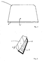
- Figure 1 is a schematic plan view showing a frameless glazing, in this case an opening backlight, formed from a single ply of toughened glass, having a trim attached along one side.
- the backlight 1 is generally rectangular in shape, having rounded corners and opposing long and short sides. One of the long sides is slightly longer than the other, giving a slight trapezoidal shape to the glazing.
- the trim 2 is attached to the longest edge of the glazing, which will form the bottom edge of the glazing when fitted into a vehicle.
- Figure 2 a schematic cross-section along the line A-A' in Figure 1 , and shows the positioning of the trim 2 on the edge of the frameless glazing 1.
- the trim 2 is generally in the shape of a "C", with the upper part of the "C” touching the surface of the glass, and the lower part positioned at a distance d from the surface of the frameless glazing 1 adjacent the edge.
- the trim 2 is bonded to the lower surface of the glazing by an adhesive 3.
- this distance d must be as small as possible.
- the amount of tolerance required is less than 1mm.
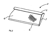
- the trim 2 is shown in more detail in Figure 3.
- Figure 3 is a part schematic perspective view of the trim 2, showing the four-part construction.
- the main body 4 of the trim 2 is formed from a thermoplastic material, such as polyurethane, and has a rough surface (indicated in part by hatched lines) to aid in the adhesion of the hot melt to the surface of the trim 2.
- the main body 4 is positioned within a chrome outer shell 5, which provides the aesthetic appearance of the trim 2. This chrome outer shell 5 wraps round the upper region of the trim 2.
- the lower region of the trim 2 is provided with a lip 6, formed from PVC (poly vinyl chloride).
- the end region of the trim 2 is provided with a cap 7, again formed from PVC. Both the lip 6 and cap 7 provide a cover for any hot melt material that escapes around the edges of the trim 2 when mounted on the frameless glazing 1. The lip 6 aids in reducing the final gap between the trim 2 and the glazing 1 seen by a viewer.
- FIG 4 is a schematic plan view of apparatus for applying a trim to a glazing, in accordance with the present invention.
- the apparatus 10 is comprises a support table 11 and manufacturing cell 12.
- the manufacturing cell 12 has means for locating the trim 2 onto the edge of the glazing 1 comprising runners 13 lying across the support table 11, over which the cell is slideable by means of handles 14, 15.
- a positioning bar 16 is provided to allow an operator to position the cell 12 for mounting of the trim 2 onto the frameless glazing 1.
- the cell 12 itself may be moved in the directions indicated by arrow A.
- the manufacturing cell 12 itself comprises two sets of suction cups: a first set of suction cups 17a to g, arranged adjacent a former 18, which is shaped to match the curvature of the frameless glazing 1, and acts to support the frameless glazing 1 during fixing of the trim 2; and a second set of suction cups 19, positioned on supports 20 (not shown), a distance away from the former 18.
- a first set of suction cups 17a - g contact the surface of the frameless glazing 1 in the region of the edge of the frameless glazing 1, and the second set 19 contact the frameless glazing 1 away from the edge, in a central region of the frameless glazing 1.
- Means for supporting the glazing 1 comprising supports 21, 22, are provided to help support the weight of the glazing, which is centred using centring means comprising two posts 23, 24 and locked into position by two grips 25.
- Vacuum suction is provided along the length of the former 18 via an array of vacuum suction holes 26, which act to maintain the position of the trim 2 during the application process.
- FIG. 5 is a schematic cross-section showing the positioning of the suction cups 17a-g, 19, on the frameless glazing 1.
- This Figure illustrates the position in which the suction cups 17a-g, 19 are in contact with the frameless glazing 1, and the trim 2 is in its final position, bonded to the surface of the frameless glazing 1.
- the frameless glazing 1 is shown as being flat, in reality it is likely to have at least a minimum curvature in at least one direction.
- the array of vacuum suction holes 26 in the former 18 are positioned within a recess 27, into which the trim 2 is placed.
- a groove 28 is provided in the upper surface of the former 18, which receives a wheel for guiding an adhesive dispensing gun (not shown) during fixing of the trim 2.
- Figure 6 shows an enlarged view of the region highlighted in Figure 4 .
- the trim 2 rests in the recess 27, with sufficient adhesive 3 to bond the trim 2 to the frameless glazing 1 without any overflow.
- the distance between the lower part of the trim 2 and the surface of the frameless glazing 1 adjacent the edge is minimised.
- the frameless glazing 1 onto which the trim 2 will be mounted positioned on the supports 20 - 22.
- the frameless glazing 1 is centered using the posts 23, 24, and then secured in position using the grips 25.
- the second set of vacuum cups 19 are then placed onto the underside surface of the frameless glazing 1, and vacuum applied. Once the frameless glazing 1 is held in place by these suction cups 19, the grips 25 are released. At this point, the frameless glazing 1 is in a first, nominal, position placing the frameless glazing 1 in which one edge of the frameless glazing 1 is free to receive the trim 2.
- the trim 2 is then prepared.
- the bond face of the trim 2 (the face to be contacted with the surface of the frameless glazing 1) is prepared by wiping with SIKA Activator, and left to dry.
- SIKA 209N primer is then applied to the bond face, and left to cure for 30 minutes.
- the region of the glazing where the trim 2 will be bonded is also prepared by wiping with SIKA Activator (wipe-on, wipe-off).
- a prepared trim 2 is then placed in the recess 27 of the former 18, and vacuum applied via vacuum suction holes 26.
- An adhesive dosing gun is then run along the groove 28 to apply a bead of SIKAMELT 9645/15 black hot melt adhesive, (having a maximum time before bonding of 40 seconds, at a temperature in the range 120°C to 170°C). The adhesive was applied at 150°C and 2 Bar, taking 25 seconds.
- SIKA-branded products are available from Sika AG, Werstrasse 50, CH-6341 Baar, Switzerland).
- a plurality of small beads may be applied, or adhesive may only be applied to selected portions of the trim 2.
- the former 18 is moved along the runners 13 until the trim 2 is in contact with the frameless glazing 1. A gap of approximately 1mm is left between the bottom edge of the trim 2 and the frameless glazing 1.
- the first set of suction cups 17a - g are then positioned against the underside surface of the frameless glazing 1, and a vacuum applied, pushing the frameless glazing into a second position and causing the glazing to deform against the trim 2, minimising the gap between the bottom edge of the trim 2 and the frameless glazing 1.
- the frameless glazing 1 is then held in this position for up to 120 seconds to allow sufficient curing of the hot melt adhesive such that the trim 2 remains in place once the vacuum cups 17a - g have been removed.
- the frameless glazing 1 having the trim 2 attached can then be removed from the apparatus 10, and the hot melt will be fully cured within 4 hours.
- the final gap d between the bottom edge of the trim 2 and the frameless glazing 1 was approximately 0.4mm at the ends of the trim 2, and between 0 and 0.1 mm along the remainder of the trim 2.
- a hot melt material is used as the adhesive
- suitable adhesives may include humidity curing polymers, and pre-applied adhesives, where the adhesive is applied to the trim 2 in the form of a number of tablets or a continuous strip, and protected by a removable cover sheet.
Landscapes
- Engineering & Computer Science (AREA)
- Mechanical Engineering (AREA)
- Automobile Manufacture Line, Endless Track Vehicle, Trailer (AREA)
- Lining Or Joining Of Plastics Or The Like (AREA)
Claims (14)
- Verfahren zum Befestigen einer Zierleiste (2) ohne tragende oder mechanische Funktion an der Kante einer rahmenlosen Automobilverglasung (1) unter Verwendung eines Klebstoffes (3) mit den folgenden Schritten:die Verglasung wird in einer ersten Stellung angeordnet, bei der eine Kante der Verglasung zum Erhalt der Zierleiste bereit ist,die Zierleiste wird in Kontakt mit der Verglasung gebracht, wobei zumindest an einem Teil der Zierleiste ein Klebstoff aufgebracht ist,die Verglasung wird in eine zweite Stellung geschoben, wodurch sich die Verglasung an die Zierleiste und den Klebstoff anformt, sodass die Zierleiste eine Bindung mit der Verglasung eingeht.
- Verfahren nach Anspruch 1, wobei der Klebstoff (2) vorab auf die Zierleiste (2) aufgebracht wird.
- Verfahren nach Anspruch 1, das ferner ein Anordnen der Zierleiste (2) im Bereich der Verglasung (1) und ein Auftragen des Klebstoffes (3) auf die Zierleiste umfasst, bevor die Zierleiste mit der Verglasung in Kontakt gebracht wird.
- Verfahren nach Anspruch 1, 2 oder 3, wobei die Verglasung (1) mit Hilfe eines ersten Satzes von Vakuumsaugnäpfen (17) in einer ersten Stellung gehalten wird.
- Verfahren nach einem der Ansprüche 1 bis 4, wobei die Verglasung (1) mit Hilfe eines zweiten Satzes von Vakuumsaugnäpfen (19) in eine zweite Stellung gebracht wird.
- Verfahren nach einem der Ansprüche 3 bis 5, wobei der Klebstoff (3) ein Schmelzklebstoff ist.
- Verfahren nach einem der Ansprüche 1 bis 6, wobei die Zierleiste mit Hilfe von Vakuumansaugung in Kontaktstellung mit der Verglasung (1) gehalten wird.
- Verfahren nach einem der vorhergehenden Ansprüche, wobei es sich bei der Verglasung (1) um ein einlagiges Glas handelt.
- Verfahren nach einem der vorhergehenden Ansprüche, wobei die Verglasung (1) an einer Vorrichtung für das Anbringen einer Zierleiste (2) an einer Kante einer rahmenlosen Verglasung in eine erste Position gebracht wird.
- Verfahren nach Anspruch 9, wobei die Vorrichtung (10) Träger (21, 22) aufweist und die Verglasung auf die Träger aufgebracht wird.
- Verfahren nach Anspruch 9 oder 10, wobei die Vorrichtung (10) ein Formstück (18) aufweist, das an die Krümmung der Verglasung (1) angepasst geformt ist und die Verglasung während der Befestigung der Zierleiste (2) stützt.
- Verfahren nach einem der Ansprüche 9 bis 11, wobei das Formstück (18) eine Ausnehmung (27) aufweist und die Zierleiste in die Ausnehmung eingebracht wird.
- Rahmenlose Automobilverglasung (1) mit einer Zierleiste (2), die unter Anwendung des Verfahrens nach einem der Ansprüche 1 bis 12 daran angebracht wurde.
- Vorrichtung (10) zum Anbringen einer Zierleiste (2) ohne tragende oder mechanische Funktion an die Kante einer rahmenlosen Automobilverglasung (1), indem die Verglasung an die Zierleiste und den Klebstoff so angeformt wird, dass die Zierleiste eine Bindung mit der Verglasung eingeht, wobei die Vorrichtung aufweist:Mittel (21, 22, 23, 24) zum Halten und Zentrieren einer rahmenlosen Automobilverglasung,einen ersten Satz von Vakuumsaugnäpfen mit wenigstens einem Saugnapf (17), um eine Vakuumansaugung an der Unterseite der Verglasung zum Halten der Verglasung in einer ersten Stellung einzusetzen,einen zweiten Satz von Vakuumsaugnäpfen mit wenigstens einem Saugnapf (19), um eine Vakuumansaugung an der Unterseite der Verglasung zum Schieben der Verglasung in eine zweite Stellung einzusetzen,eine Ausnehmung (27) zum Aufnehmen einer Zierleiste, wobei die Ausnehmung mehrere Vakuumsauglöcher (26) aufweist, um die Zierleiste in einer Kontaktstellung mit der Verglasung zu halten, undMittel zum Anordnen der Zierleiste an der Kante der Verglasung.
Priority Applications (1)
| Application Number | Priority Date | Filing Date | Title |
|---|---|---|---|
| EP08854642A EP2214932B1 (de) | 2007-11-27 | 2008-11-27 | Verglasung |
Applications Claiming Priority (3)
| Application Number | Priority Date | Filing Date | Title |
|---|---|---|---|
| EP07425747 | 2007-11-27 | ||
| EP08854642A EP2214932B1 (de) | 2007-11-27 | 2008-11-27 | Verglasung |
| PCT/EP2008/066361 WO2009068624A1 (en) | 2007-11-27 | 2008-11-27 | Glazing |
Publications (2)
| Publication Number | Publication Date |
|---|---|
| EP2214932A1 EP2214932A1 (de) | 2010-08-11 |
| EP2214932B1 true EP2214932B1 (de) | 2011-08-24 |
Family
ID=39431183
Family Applications (1)
| Application Number | Title | Priority Date | Filing Date |
|---|---|---|---|
| EP08854642A Not-in-force EP2214932B1 (de) | 2007-11-27 | 2008-11-27 | Verglasung |
Country Status (5)
| Country | Link |
|---|---|
| US (1) | US20100304070A1 (de) |
| EP (1) | EP2214932B1 (de) |
| JP (1) | JP5318114B2 (de) |
| AT (1) | ATE521504T1 (de) |
| WO (1) | WO2009068624A1 (de) |
Families Citing this family (7)
| Publication number | Priority date | Publication date | Assignee | Title |
|---|---|---|---|---|
| FR2958877B1 (fr) | 2010-04-16 | 2012-11-09 | Saint Gobain | Procede et dispositif de fabrication d'un vitrage comportant un film decoratif et vitrage comportant un film decoratif. |
| US9180565B2 (en) | 2011-03-24 | 2015-11-10 | Pilkington Group Limited | Decorative trim assembly fixture and method of using same |
| US10240930B2 (en) | 2013-12-10 | 2019-03-26 | SZ DJI Technology Co., Ltd. | Sensor fusion |
| EP3399381A1 (de) | 2014-09-05 | 2018-11-07 | SZ DJI Technology Co., Ltd. | Kontextbasierte flugmodusauswahl |
| JP6181300B2 (ja) | 2014-09-05 | 2017-08-16 | エスゼット ディージェイアイ テクノロジー カンパニー リミテッドSz Dji Technology Co.,Ltd | 無人航空機の速度を制御するシステム |
| EP3428766B1 (de) | 2014-09-05 | 2021-04-07 | SZ DJI Technology Co., Ltd. | Abbildung von multisensorumgebungen |
| US11752954B2 (en) | 2021-04-06 | 2023-09-12 | Toyota Motor Engineering & Manufacturing North America, Inc. | Vehicle interior trim securing systems and associated methods |
Family Cites Families (12)
| Publication number | Priority date | Publication date | Assignee | Title |
|---|---|---|---|---|
| US3705470A (en) * | 1969-03-21 | 1972-12-12 | Creators Ltd | Glazing windows or windscreen openings, particularly in vehicle bodies |
| US3971178A (en) * | 1974-03-25 | 1976-07-27 | Ppg Industries, Inc. | Add-on multiple glazing with hygroscopic material |
| DE2555195C3 (de) | 1975-12-09 | 1986-10-02 | Dr.Ing.H.C. F. Porsche Ag, 7000 Stuttgart | Schwenkbare Klappe, insbesondere am Heck eines PKWs |
| JPH0669783B2 (ja) * | 1985-10-04 | 1994-09-07 | 日産自動車株式会社 | 自動車のボデイサイド構造 |
| JPH059935Y2 (de) * | 1987-09-17 | 1993-03-11 | ||
| JP3056531B2 (ja) * | 1990-12-27 | 2000-06-26 | 東海興業株式会社 | シール体付きパネルの製造方法及び製造装置 |
| US5380978A (en) * | 1991-07-12 | 1995-01-10 | Pryor; Timothy R. | Method and apparatus for assembly of car bodies and other 3-dimensional objects |
| JPH08127233A (ja) * | 1994-10-31 | 1996-05-21 | Suzuki Motor Corp | 固定式側窓構造 |
| JP3269295B2 (ja) * | 1994-11-29 | 2002-03-25 | 三菱自動車工業株式会社 | 窓ガラスへの成形ストリップの装着方法 |
| US6382696B1 (en) * | 2001-08-06 | 2002-05-07 | Creative Extruded Products, Inc. | Window trim molding |
| TW200505626A (en) * | 2003-01-29 | 2005-02-16 | Mitsuboshi Diamond Ind Co Ltd | Vacuum suction head |
| US7797882B2 (en) * | 2003-05-14 | 2010-09-21 | Ford Global Technologies, Llc | Window positioning apparatus |
-
2008
- 2008-11-27 JP JP2010535386A patent/JP5318114B2/ja not_active Expired - Fee Related
- 2008-11-27 WO PCT/EP2008/066361 patent/WO2009068624A1/en not_active Ceased
- 2008-11-27 US US12/744,892 patent/US20100304070A1/en not_active Abandoned
- 2008-11-27 EP EP08854642A patent/EP2214932B1/de not_active Not-in-force
- 2008-11-27 AT AT08854642T patent/ATE521504T1/de not_active IP Right Cessation
Also Published As
| Publication number | Publication date |
|---|---|
| US20100304070A1 (en) | 2010-12-02 |
| JP5318114B2 (ja) | 2013-10-16 |
| WO2009068624A1 (en) | 2009-06-04 |
| ATE521504T1 (de) | 2011-09-15 |
| JP2011504850A (ja) | 2011-02-17 |
| EP2214932A1 (de) | 2010-08-11 |
Similar Documents
| Publication | Publication Date | Title |
|---|---|---|
| US20100304070A1 (en) | Glazing | |
| JPH066311B2 (ja) | モールまたはホルダー付板状体の製造方法 | |
| CN108260353B (zh) | 具有内部突起的滑动叠层玻璃窗单元 | |
| RU2740742C2 (ru) | Многослойное стекло с очень тонким внутренним стеклом, установленным с отступом | |
| CN113165334B (zh) | 用于3d冷成型弯曲层合物的均匀粘合剂粘结线控制的方法 | |
| US11511466B2 (en) | Decorative part for a motor vehicle | |
| CN114506193A (zh) | 具有棱边保护部的车辆玻璃板 | |
| CN1635966A (zh) | 机动车顶盖模件和将该模件装配到机动车上的方法 | |
| US5343662A (en) | Auto glass moulding and dam | |
| JPH06170883A (ja) | 樹脂製ウィンド部材の製造方法 | |
| US20250332888A1 (en) | Vehicle window assembly with bonded perimeter frame | |
| US7604280B2 (en) | Devices and methods for locating fixed glass panes on automotive vehicles | |
| EP3529133B1 (de) | Klebstoffanwendung mit variablem verhältnis | |
| US20050218557A1 (en) | Method and device for producing a profiled trim section for a glass pane | |
| EP1567381B1 (de) | Dichtungs-führungs-und randstreifenvorrichtung und deren herstellungsverfahren | |
| JPH03505560A (ja) | 保持用シールドを備える窓材アセンブリ及びその製造方法 | |
| CN211222991U (zh) | 一种顶棚天窗口翻边结构 | |
| US20240270056A1 (en) | Vehicular window assembly with flexible perimeter frame | |
| JPH0661529U (ja) | 自動車のウインドシールド取り付け構造 | |
| KR20250073625A (ko) | 윈도우 유닛, 차량 윈도우 유닛, 금형, 및 관련 방법 및 용도 | |
| CN121039012A (zh) | 交通工具嵌装玻璃组件、交通工具顶棚、模具以及相关联的方法和用途 | |
| KR20200015156A (ko) | 선루프용 이중 진공유리 및 그의 제조방법 | |
| JPH0422989Y2 (de) | ||
| EP3960415A1 (de) | Verfahren zur herstellung eines wasserschutzes für fahrzeugtüren und so hergestelltes produkt | |
| CN120677074A (zh) | 窗户单元、组装好的窗户单元、模具以及相关联的方法和用途 |
Legal Events
| Date | Code | Title | Description |
|---|---|---|---|
| PUAI | Public reference made under article 153(3) epc to a published international application that has entered the european phase |
Free format text: ORIGINAL CODE: 0009012 |
|
| 17P | Request for examination filed |
Effective date: 20100628 |
|
| AK | Designated contracting states |
Kind code of ref document: A1 Designated state(s): AT BE BG CH CY CZ DE DK EE ES FI FR GB GR HR HU IE IS IT LI LT LU LV MC MT NL NO PL PT RO SE SI SK TR |
|
| AX | Request for extension of the european patent |
Extension state: AL BA MK RS |
|
| DAX | Request for extension of the european patent (deleted) | ||
| GRAP | Despatch of communication of intention to grant a patent |
Free format text: ORIGINAL CODE: EPIDOSNIGR1 |
|
| GRAS | Grant fee paid |
Free format text: ORIGINAL CODE: EPIDOSNIGR3 |
|
| GRAA | (expected) grant |
Free format text: ORIGINAL CODE: 0009210 |
|
| AK | Designated contracting states |
Kind code of ref document: B1 Designated state(s): AT BE BG CH CY CZ DE DK EE ES FI FR GB GR HR HU IE IS IT LI LT LU LV MC MT NL NO PL PT RO SE SI SK TR |
|
| REG | Reference to a national code |
Ref country code: GB Ref legal event code: FG4D |
|
| REG | Reference to a national code |
Ref country code: CH Ref legal event code: EP |
|
| REG | Reference to a national code |
Ref country code: IE Ref legal event code: FG4D |
|
| REG | Reference to a national code |
Ref country code: DE Ref legal event code: R096 Ref document number: 602008009180 Country of ref document: DE Effective date: 20111027 |
|
| REG | Reference to a national code |
Ref country code: NL Ref legal event code: VDEP Effective date: 20110824 |
|
| LTIE | Lt: invalidation of european patent or patent extension |
Effective date: 20110824 |
|
| PG25 | Lapsed in a contracting state [announced via postgrant information from national office to epo] |
Ref country code: PT Free format text: LAPSE BECAUSE OF FAILURE TO SUBMIT A TRANSLATION OF THE DESCRIPTION OR TO PAY THE FEE WITHIN THE PRESCRIBED TIME-LIMIT Effective date: 20111226 Ref country code: HR Free format text: LAPSE BECAUSE OF FAILURE TO SUBMIT A TRANSLATION OF THE DESCRIPTION OR TO PAY THE FEE WITHIN THE PRESCRIBED TIME-LIMIT Effective date: 20110824 Ref country code: SE Free format text: LAPSE BECAUSE OF FAILURE TO SUBMIT A TRANSLATION OF THE DESCRIPTION OR TO PAY THE FEE WITHIN THE PRESCRIBED TIME-LIMIT Effective date: 20110824 Ref country code: LT Free format text: LAPSE BECAUSE OF FAILURE TO SUBMIT A TRANSLATION OF THE DESCRIPTION OR TO PAY THE FEE WITHIN THE PRESCRIBED TIME-LIMIT Effective date: 20110824 Ref country code: FI Free format text: LAPSE BECAUSE OF FAILURE TO SUBMIT A TRANSLATION OF THE DESCRIPTION OR TO PAY THE FEE WITHIN THE PRESCRIBED TIME-LIMIT Effective date: 20110824 Ref country code: NO Free format text: LAPSE BECAUSE OF FAILURE TO SUBMIT A TRANSLATION OF THE DESCRIPTION OR TO PAY THE FEE WITHIN THE PRESCRIBED TIME-LIMIT Effective date: 20111124 Ref country code: NL Free format text: LAPSE BECAUSE OF FAILURE TO SUBMIT A TRANSLATION OF THE DESCRIPTION OR TO PAY THE FEE WITHIN THE PRESCRIBED TIME-LIMIT Effective date: 20110824 Ref country code: IS Free format text: LAPSE BECAUSE OF FAILURE TO SUBMIT A TRANSLATION OF THE DESCRIPTION OR TO PAY THE FEE WITHIN THE PRESCRIBED TIME-LIMIT Effective date: 20111224 |
|
| REG | Reference to a national code |
Ref country code: AT Ref legal event code: MK05 Ref document number: 521504 Country of ref document: AT Kind code of ref document: T Effective date: 20110824 |
|
| PG25 | Lapsed in a contracting state [announced via postgrant information from national office to epo] |
Ref country code: SI Free format text: LAPSE BECAUSE OF FAILURE TO SUBMIT A TRANSLATION OF THE DESCRIPTION OR TO PAY THE FEE WITHIN THE PRESCRIBED TIME-LIMIT Effective date: 20110824 Ref country code: LV Free format text: LAPSE BECAUSE OF FAILURE TO SUBMIT A TRANSLATION OF THE DESCRIPTION OR TO PAY THE FEE WITHIN THE PRESCRIBED TIME-LIMIT Effective date: 20110824 Ref country code: GR Free format text: LAPSE BECAUSE OF FAILURE TO SUBMIT A TRANSLATION OF THE DESCRIPTION OR TO PAY THE FEE WITHIN THE PRESCRIBED TIME-LIMIT Effective date: 20111125 Ref country code: CY Free format text: LAPSE BECAUSE OF FAILURE TO SUBMIT A TRANSLATION OF THE DESCRIPTION OR TO PAY THE FEE WITHIN THE PRESCRIBED TIME-LIMIT Effective date: 20110824 Ref country code: PL Free format text: LAPSE BECAUSE OF FAILURE TO SUBMIT A TRANSLATION OF THE DESCRIPTION OR TO PAY THE FEE WITHIN THE PRESCRIBED TIME-LIMIT Effective date: 20110824 Ref country code: AT Free format text: LAPSE BECAUSE OF FAILURE TO SUBMIT A TRANSLATION OF THE DESCRIPTION OR TO PAY THE FEE WITHIN THE PRESCRIBED TIME-LIMIT Effective date: 20110824 |
|
| PG25 | Lapsed in a contracting state [announced via postgrant information from national office to epo] |
Ref country code: BE Free format text: LAPSE BECAUSE OF FAILURE TO SUBMIT A TRANSLATION OF THE DESCRIPTION OR TO PAY THE FEE WITHIN THE PRESCRIBED TIME-LIMIT Effective date: 20110824 |
|
| PG25 | Lapsed in a contracting state [announced via postgrant information from national office to epo] |
Ref country code: CZ Free format text: LAPSE BECAUSE OF FAILURE TO SUBMIT A TRANSLATION OF THE DESCRIPTION OR TO PAY THE FEE WITHIN THE PRESCRIBED TIME-LIMIT Effective date: 20110824 Ref country code: SK Free format text: LAPSE BECAUSE OF FAILURE TO SUBMIT A TRANSLATION OF THE DESCRIPTION OR TO PAY THE FEE WITHIN THE PRESCRIBED TIME-LIMIT Effective date: 20110824 |
|
| PG25 | Lapsed in a contracting state [announced via postgrant information from national office to epo] |
Ref country code: IT Free format text: LAPSE BECAUSE OF FAILURE TO SUBMIT A TRANSLATION OF THE DESCRIPTION OR TO PAY THE FEE WITHIN THE PRESCRIBED TIME-LIMIT Effective date: 20110824 Ref country code: RO Free format text: LAPSE BECAUSE OF FAILURE TO SUBMIT A TRANSLATION OF THE DESCRIPTION OR TO PAY THE FEE WITHIN THE PRESCRIBED TIME-LIMIT Effective date: 20110824 Ref country code: EE Free format text: LAPSE BECAUSE OF FAILURE TO SUBMIT A TRANSLATION OF THE DESCRIPTION OR TO PAY THE FEE WITHIN THE PRESCRIBED TIME-LIMIT Effective date: 20110824 |
|
| PG25 | Lapsed in a contracting state [announced via postgrant information from national office to epo] |
Ref country code: MC Free format text: LAPSE BECAUSE OF NON-PAYMENT OF DUE FEES Effective date: 20111130 Ref country code: DK Free format text: LAPSE BECAUSE OF FAILURE TO SUBMIT A TRANSLATION OF THE DESCRIPTION OR TO PAY THE FEE WITHIN THE PRESCRIBED TIME-LIMIT Effective date: 20110824 |
|
| PLBE | No opposition filed within time limit |
Free format text: ORIGINAL CODE: 0009261 |
|
| STAA | Information on the status of an ep patent application or granted ep patent |
Free format text: STATUS: NO OPPOSITION FILED WITHIN TIME LIMIT |
|
| 26N | No opposition filed |
Effective date: 20120525 |
|
| REG | Reference to a national code |
Ref country code: IE Ref legal event code: MM4A |
|
| REG | Reference to a national code |
Ref country code: DE Ref legal event code: R097 Ref document number: 602008009180 Country of ref document: DE Effective date: 20120525 |
|
| PG25 | Lapsed in a contracting state [announced via postgrant information from national office to epo] |
Ref country code: IE Free format text: LAPSE BECAUSE OF NON-PAYMENT OF DUE FEES Effective date: 20111127 |
|
| PG25 | Lapsed in a contracting state [announced via postgrant information from national office to epo] |
Ref country code: MT Free format text: LAPSE BECAUSE OF FAILURE TO SUBMIT A TRANSLATION OF THE DESCRIPTION OR TO PAY THE FEE WITHIN THE PRESCRIBED TIME-LIMIT Effective date: 20110824 |
|
| PG25 | Lapsed in a contracting state [announced via postgrant information from national office to epo] |
Ref country code: ES Free format text: LAPSE BECAUSE OF FAILURE TO SUBMIT A TRANSLATION OF THE DESCRIPTION OR TO PAY THE FEE WITHIN THE PRESCRIBED TIME-LIMIT Effective date: 20111205 |
|
| PG25 | Lapsed in a contracting state [announced via postgrant information from national office to epo] |
Ref country code: LU Free format text: LAPSE BECAUSE OF NON-PAYMENT OF DUE FEES Effective date: 20111127 |
|
| PG25 | Lapsed in a contracting state [announced via postgrant information from national office to epo] |
Ref country code: BG Free format text: LAPSE BECAUSE OF FAILURE TO SUBMIT A TRANSLATION OF THE DESCRIPTION OR TO PAY THE FEE WITHIN THE PRESCRIBED TIME-LIMIT Effective date: 20111124 |
|
| REG | Reference to a national code |
Ref country code: CH Ref legal event code: PL |
|
| GBPC | Gb: european patent ceased through non-payment of renewal fee |
Effective date: 20121127 |
|
| PG25 | Lapsed in a contracting state [announced via postgrant information from national office to epo] |
Ref country code: CH Free format text: LAPSE BECAUSE OF NON-PAYMENT OF DUE FEES Effective date: 20121130 Ref country code: LI Free format text: LAPSE BECAUSE OF NON-PAYMENT OF DUE FEES Effective date: 20121130 |
|
| PG25 | Lapsed in a contracting state [announced via postgrant information from national office to epo] |
Ref country code: TR Free format text: LAPSE BECAUSE OF FAILURE TO SUBMIT A TRANSLATION OF THE DESCRIPTION OR TO PAY THE FEE WITHIN THE PRESCRIBED TIME-LIMIT Effective date: 20110824 |
|
| PG25 | Lapsed in a contracting state [announced via postgrant information from national office to epo] |
Ref country code: HU Free format text: LAPSE BECAUSE OF FAILURE TO SUBMIT A TRANSLATION OF THE DESCRIPTION OR TO PAY THE FEE WITHIN THE PRESCRIBED TIME-LIMIT Effective date: 20110824 |
|
| PG25 | Lapsed in a contracting state [announced via postgrant information from national office to epo] |
Ref country code: GB Free format text: LAPSE BECAUSE OF NON-PAYMENT OF DUE FEES Effective date: 20121127 |
|
| PGFP | Annual fee paid to national office [announced via postgrant information from national office to epo] |
Ref country code: FR Payment date: 20131108 Year of fee payment: 6 Ref country code: DE Payment date: 20131120 Year of fee payment: 6 |
|
| REG | Reference to a national code |
Ref country code: DE Ref legal event code: R119 Ref document number: 602008009180 Country of ref document: DE |
|
| REG | Reference to a national code |
Ref country code: FR Ref legal event code: ST Effective date: 20150731 |
|
| PG25 | Lapsed in a contracting state [announced via postgrant information from national office to epo] |
Ref country code: DE Free format text: LAPSE BECAUSE OF NON-PAYMENT OF DUE FEES Effective date: 20150602 |
|
| PG25 | Lapsed in a contracting state [announced via postgrant information from national office to epo] |
Ref country code: FR Free format text: LAPSE BECAUSE OF NON-PAYMENT OF DUE FEES Effective date: 20141201 |