EP2226400A1 - Verfahren zur Kühlung eines umlaufenden Metallbands in einem Kühlabschnitt einer kontinuierlichen Wärmebehandlungsanlage, und Anlage zur Durchführung dieses Verfahrens - Google Patents
Verfahren zur Kühlung eines umlaufenden Metallbands in einem Kühlabschnitt einer kontinuierlichen Wärmebehandlungsanlage, und Anlage zur Durchführung dieses Verfahrens Download PDFInfo
- Publication number
- EP2226400A1 EP2226400A1 EP10290086A EP10290086A EP2226400A1 EP 2226400 A1 EP2226400 A1 EP 2226400A1 EP 10290086 A EP10290086 A EP 10290086A EP 10290086 A EP10290086 A EP 10290086A EP 2226400 A1 EP2226400 A1 EP 2226400A1
- Authority
- EP
- European Patent Office
- Prior art keywords
- refrigerant
- strip
- cooling
- temperature
- phase
- Prior art date
- Legal status (The legal status is an assumption and is not a legal conclusion. Google has not performed a legal analysis and makes no representation as to the accuracy of the status listed.)
- Granted
Links
Images
Classifications
-
- C—CHEMISTRY; METALLURGY
- C21—METALLURGY OF IRON
- C21D—MODIFYING THE PHYSICAL STRUCTURE OF FERROUS METALS; GENERAL DEVICES FOR HEAT TREATMENT OF FERROUS OR NON-FERROUS METALS OR ALLOYS; MAKING METAL MALLEABLE, e.g. BY DECARBURISATION OR TEMPERING
- C21D9/00—Heat treatment, e.g. annealing, hardening, quenching or tempering, adapted for particular articles; Furnaces therefor
- C21D9/52—Heat treatment, e.g. annealing, hardening, quenching or tempering, adapted for particular articles; Furnaces therefor for wires; for strips ; for rods of unlimited length
- C21D9/54—Furnaces for treating strips or wire
- C21D9/56—Continuous furnaces for strip or wire
- C21D9/573—Continuous furnaces for strip or wire with cooling
-
- F—MECHANICAL ENGINEERING; LIGHTING; HEATING; WEAPONS; BLASTING
- F27—FURNACES; KILNS; OVENS; RETORTS
- F27B—FURNACES, KILNS, OVENS OR RETORTS IN GENERAL; OPEN SINTERING OR LIKE APPARATUS
- F27B9/00—Furnaces through which the charge is moved mechanically, e.g. of tunnel type; Similar furnaces in which the charge moves by gravity
- F27B9/12—Furnaces through which the charge is moved mechanically, e.g. of tunnel type; Similar furnaces in which the charge moves by gravity with special arrangements for preheating or cooling the charge
-
- F—MECHANICAL ENGINEERING; LIGHTING; HEATING; WEAPONS; BLASTING
- F27—FURNACES; KILNS; OVENS; RETORTS
- F27D—DETAILS OR ACCESSORIES OF FURNACES, KILNS, OVENS OR RETORTS, IN SO FAR AS THEY ARE OF KINDS OCCURRING IN MORE THAN ONE KIND OF FURNACE
- F27D9/00—Cooling of furnaces or of charges therein
-
- F—MECHANICAL ENGINEERING; LIGHTING; HEATING; WEAPONS; BLASTING
- F25—REFRIGERATION OR COOLING; COMBINED HEATING AND REFRIGERATION SYSTEMS; HEAT PUMP SYSTEMS; MANUFACTURE OR STORAGE OF ICE; LIQUEFACTION SOLIDIFICATION OF GASES
- F25D—REFRIGERATORS; COLD ROOMS; ICE-BOXES; COOLING OR FREEZING APPARATUS NOT OTHERWISE PROVIDED FOR
- F25D3/00—Devices using other cold materials; Devices using cold-storage bodies
- F25D3/12—Devices using other cold materials; Devices using cold-storage bodies using solidified gases, e.g. carbon-dioxide snow
Definitions
- the present invention relates to the cooling of a metal strip flowing in a cooling section of a continuous heat treatment line, such as a metal or organic annealing or coating line.
- the cooling of the metal strips is carried out in a cooling section by blowing a gas, generally a mixture of nitrogen and hydrogen, through one or more chambers of cooling, equipped with holes or associated blowing tubes.
- a gas generally a mixture of nitrogen and hydrogen
- the constant concern of the designers of the cooling sections is both to cool as evenly as possible the band flowing in said section, and to avoid inducing instabilities and / or vibrations at the circulating strip.
- the document EP-A-1,655,383 illustrates such a cooling device, in which a band circulates between two cooling boxes equipped with inclined blow tubes, at an inclination which is directed both upstream and / or downstream of the band in circulation, and towards the edges of it.
- the strip is thus cooled on both sides by blowing the gaseous mixture concerned at a temperature below that of the strip.
- the pressure required for blowing is provided by one or two associated fans.
- the gaseous mixture heated by the heat exchange with the strip is cooled in a heat exchanger, generally a water exchanger, to be subsequently transferred to the cooling system via the fan or fans, being recirculated to the cooling chambers. cooling.
- the heat transfer is dependent on the blowing distance between the strip and the outlet orifices of the gas mixture, and also on the geometry of the blowing and the blowing speed. It is well known that the heat transfer is more effective when the blowing distance is small and / or the blowing speed is high. However, there is a practical limit in increasing the blowing speed and in reducing the distance between the strip and the blowing system, since, starting from a certain threshold, there is the appearance of vibrations and / or oscillations of the band which can cause contact between the band and the blowing system, and create marks incompatible with the desired surface quality or even more seriously damage the band.
- water has also been used as a cooling fluid, as illustrated in the document EP-A-0 343 103 wherein the rapid cooling of the strip is effected by means of water / air mist nozzles, or alternatively in the document FR-A-2,796,965 wherein water / nitrogen nozzles are used.
- water / air mist nozzles or alternatively in the document FR-A-2,796,965 wherein water / nitrogen nozzles are used.
- the use of water as a coolant is of interest since heat transfer requires lower output speeds for the coolant, since it is based on heat exchange by evaporation of the water in the coolant. air or nitrogen, but this use has two major disadvantages.
- the first drawback is that the heat transfer is limited by the saturation temperature of the water in the air or nitrogen non-condensable gases, and the second is that the high temperature steel inevitably undergoes oxidation when cooled by water / air or water / nitrogen fog, which in turn requires special stripping treatment which can be costly, and sometimes even impossible to perform in some lines such as galvanizing.
- the object of the invention is to design a method and a cooling installation for cooling a moving metal strip with a high cooling rate, without generating vibrations and / or oscillations, while avoiding the need for a stripping or special surface treatment as a result of the cooling which would be the consequence of a more or less significant oxidation of the surface of the strip.
- the aforementioned technical problem is solved according to the invention by a method of cooling a metal strip circulating in a cooling section of a continuous heat treatment line, consisting in projecting into the cooling section, on the surface of the strip to be cooled, a refrigerant capable of cooling the strip without oxidizing said strip, said process being remarkable in that the refrigerant medium is mainly composed of a phase-change body whose passage in the gaseous phase takes place at a temperature that is at once lower than the temperature of the strip to be cooled and close to the ambient ambient temperature, so that the energy exchange is performed as part of an endothermic process with a phase change of said phase change body and then said refrigerant can be recondensed to a pressure close to atmospheric pressure.
- the refrigerant medium is in solid form, in particular in the form of flakes, having a triple point which is greater than the ambient ambient temperature, the endothermic process being performing with a sublimation of said refrigerant at the surface of the strip to be cooled.
- the refrigerant medium is a fluid, in particular in the form of fine droplets, having a normal boiling temperature which is higher than the ambient ambient temperature, the process endothermic being carried out with evaporation of said refrigerant at the surface of the strip to cool.
- the sublimed refrigerant or the evaporated refrigerant is recovered downstream of the cooling section to be recirculated, having undergone a condensation and separation process at the end of which a fraction of incondensables is isolated, said fraction being controlled to adjust the condensing temperature of the solid or refrigerant to minimize energy consumption.
- said fluid has at least 80% volume per volume of phase change fluid.
- the phase-change fluid is pentane.
- This may be pentane in the pure state, or alternatively a pentane / hexane mixture with 80/20 molar percentage.
- the atmosphere prevailing in the cooling section is isolated from the ambient outside environment, in particular at the inlet and the outlet of the strip to be cooled, so as to allow permanent control of the refrigerant during the endothermic process. This is important not only for economic reasons, but also for safety reasons as some fluids that can be used can be flammable at high temperatures and therefore should not be mixed with the oxygen of the fuel. 'air.
- the flow rate of refrigerant medium projected onto the surface of the strip is controlled to remain below a predetermined limit making the entire refrigerant medium is concerned by the change of phase.
- the invention also relates to an installation intended for the implementation of a method having at least one of the abovementioned characteristics.
- the nozzles of the cooling box are arranged with a segmentation, so as to follow a predetermined cooling slope as a function of the running speed of the strip.
- the cooling box comprises an upstream section free of nozzles and a downstream section equipped with nozzles, with reference to the direction of circulation of the strip, said upstream section being equipped with a sensor for measuring the temperature of the band entering said box.
- the cooling box is equipped, at the inlet and the outlet of the strip, airtight crossing chambers.
- the installation comprises sensors for measuring the temperature of the strip upstream of the inlet and downstream of the outlet of the cooling box, said sensors serving to regulate the flow rate of the pump. recirculation as a function of the running speed of said band, which running speed is measured by an associated sensor outside said cooling box.
- the tank / separator tank is internally equipped with a cooling coil operating at a temperature which is lower than the condensing temperature of the refrigerant medium used, in order to complete in said flask the processes of condensation and separation of the liquid phase. refrigerant and incondensable gases.
- the tank / separator tank is equipped with a purge for extracting the incondensable gases.
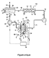
- the single figure schematically illustrates a rated installation 100 of implementation of the cooling method according to the invention.
- a metal strip marked 1 flows in a cooling section denoted 4 of a continuous heat treatment line, which could be a line of annealing or metal or organic coating.
- the line of passage of the band 1 is fixed by a lower return roller 2 and an upper return roller 3, on either side of the cooling section 4, the direction of circulation of the band 1 being shown schematically by arrows 50.
- the cooling section 4 comprises a cooling box 5 which is crossed by the strip to be cooled 1.
- the cooling box 5 is closed, and the crossing of the strip is effected in a sealed manner at the level of the airlock and output 8, 9 which are shown schematically here. It may be systems with flaps cooperating or not with support rollers, as is well known in the field of continuous treatment lines. Thanks to the input and output lock 8, 9, it is ensured that the atmosphere prevailing in the cooling section 4 is isolated from the ambient external environment, in particular at the inlet and the outlet of the strip. cool, so as to allow a permanent control of the refrigerant medium during cooling of said strip.
- the cooling box 5 is internally equipped with projection ramps 6 arranged on either side of the passage plane of the strip, each ramp itself being provided with a plurality of spray nozzles 7 for projecting into the section. 4, on the surface of the strip 1 to be cooled, a particular refrigerant capable of cooling the strip without oxidizing said strip (unlike water often used in prior techniques).
- a refrigerant medium mainly composed of a phase-change body whose passage in the gaseous phase takes place at a temperature which is at the lower than the temperature of the strip to be cooled and close to the ambient external environment, so that the energy exchange is carried out as part of an endothermic process with a phase change of said phase-change body, and then said refrigerant can be recondensed to a pressure close to atmospheric pressure.
- the refrigerant medium is in solid form, in particular in the form of flakes, having a triple point which is greater than the ambient ambient temperature, the endothermic process being performed with a sublimation of said refrigerant medium at the surface of the strip to be cooled.
- CO 2 can be used .
- the refrigerant is a fluid, in particular in the form of fine droplets, having a normal boiling temperature which is higher than the temperature. ambient external environment, the endothermic process being performed with an evaporation of said refrigerant at the surface of the strip to be cooled.
- the sublimed refrigerant or the evaporated refrigerant is recovered downstream of the cooling section 4 to be recirculated, having undergone a condensation and separation process at the end of which a fraction of incondensables is isolated, said fraction being controlled to adjust the condensing temperature of the solid or the refrigerant in order to minimize the energy consumption.
- a refrigerant which comprises at least 80% volume per volume of phase-change fluid.
- pentane in the pure state, in particular liquid pentane, which evaporates at 35 ° C. under its own vapor pressure, therefore at ambient pressure.
- It may alternatively be a mixture comprising predominantly pentane, with preferably at least 80% volume by volume of pentane.
- pentane is of particular interest because of its normal boiling temperature of the order of 35 ° C, because it is sufficient to organize the heat exchange in a well sized exchanger with an external fluid (air or water) to condense it.
- the refrigerant mass flow rate projected on the surface of the strip will preferably be controlled to remain below a predetermined limit so that all of the refrigerant is affected by the phase change.
- flat cone spray nozzles are preferably used.
- the droplets impacting the two faces of the strip then instantaneously undergo a phase change which induces a high energy absorption.
- the injected refrigerant mass flow rate that evaporates depends, of course, on the number of spray nozzles used and the mass flow rate of each of them.
- the geometric distribution of the spray nozzles depends on their angle of action, which is chosen so that the droplets impact the entire cooling surface.
- this prior document relates only to the blow-cooling of a traditional gaseous mixture such as a mixture of nitrogen and hydrogen. It may also be provided that the spray nozzles are arranged with a segmentation, so as to follow a predetermined cooling slope according to the running speed of the band.
- the installation 100 also comprises a condenser 13 connected downstream of the cooling box 5 via a booster 10 via respective ducts 11 and 12, which allows the refrigerant to be recondensed to a pressure close to atmospheric pressure.
- the pipe 12 essentially containing a vapor phase is extended by a section 12 'in the condenser 13, which is produced here in the form of a conventional exchanger using an exchange circuit 14 traversed by water or air .
- the outlet line 15 of the condenser 13 terminates in a balloon 16 which forms a reservoir and separator. There is indeed a liquid phase and incondensables that arrive together in this balloon 16, these two phases separating into a liquid reserve RL surmounted by a fraction of incondensable gas IG.
- the incondensables present in the refrigerant which are typically nitrogen and possibly traces of hydrogen.
- the cooling box 5 illustrated here comprises an upstream section 5.1 free of nozzles 7, and a downstream section 5.2 which is equipped with nozzles 7, with reference to the flow direction 50 of the strip 1.
- the upstream section 5.1 is equipped with a sensor 34 which is used to measure the temperature of the band 1 entering said box. Due to the absence of nozzles, it can thus be ascertained, by an optical measurement of the temperature of the strip, that the totality of the refrigerant medium has turned into gas. Any droplet that has not undergone the phase transformation will flow into this section and will be evaporated, or sublimated when it comes to flakes.
- the installation also comprises sensors 32, 33 for measuring the temperature of the strip 1, respectively upstream of the inlet and downstream of the outlet of the cooling box 5. These sensors 32, 33 serve to regulate the flow rate of the recirculation pump 22 as a function of the running speed of said band, which running speed is measured by an associated sensor 31 outside the cooling box 5.
- Diagrammatically illustrated a central control unit 30 which receives information given by the speed sensor 31 and the temperature sensors 32, 33, 34, this information being transmitted by a wired network shown in phantom.
- This control unit 30 makes it possible to send very precise operating instructions to the control member 35 of the recirculation pump 22.
- the tank / separator tank 16 is internally equipped with a cooling coil 17, using its own refrigerant, which naturally runs at a temperature which is lower than the condensing temperature of the phase-change refrigerant. used for cooling the tape.
- This cooling coil 17 makes it possible to complete in the flask 16 the processes for condensing and separating the liquid phase from the refrigerant medium and the incondensable gases.
- the control of incondensables in the refrigerant is important because it makes it possible to adjust the condensing temperature: in fact, the lower the incondensable content, the lower the condensation temperature of the phase-change fluid.
- the cooling coil 17 will typically operate at a temperature of 15 K to ensure further condensation of the phase change refrigerant and achieve the desired separation. It is then ensured that the incondensables accumulated at the cooling section are well separated from the working refrigerant, and that all the fluid to be pumped to the spray nozzles 7 is in the liquid state.
- the safety valve 20 makes it possible for the circulation of the refrigerant to stop in case of emergency, such as the massive infiltration of air, or a malfunction of one of the elements of the circuit, a stop of movement of the band. , etc ...
- the liquid refrigerant is pumped by the recirculation pump 22 to be sent directly to the spray nozzles 7 to resume the cycle.
- the flow rate of the recirculation pump 22 is regulated by a controller (the unit 30) which uses as input data the temperatures of the input and output band of the control chamber. cooling, as well as the speed of circulation of the band. These data make it possible to effectively control the system, since the quantity of heat to be extracted from the band is naturally a function of the speed of its movement and the set point of the outlet temperature of the band, and also the differences in temperature between the inlet and the outlet of the cooling chamber. This amount of heat thus conditions the flow rate of the pump, and therefore the amount of refrigerant sprayed onto the strip.
- the sealing chambers 8, 9 fitted to the cooling box 5 are particularly important when pentane is used, as has been advocated above, not only for reasons of economy (this would be true with any type of coolant), but especially for security reasons.
- pentane like other analogous fluids conceivable, are flammable at high temperature (309 ° C for pentane), and should not be mixed with oxygen in the air.
- the pentane composition in the box will therefore be continuously measured and monitored to be still well above the upper limit of flammability in the air. As such, it will be interesting to maintain the cooling box slightly overpressure. We can also provide an additional probe to monitor the percentage of oxygen in the atmosphere of the cooling box.
- the work of the booster is regulated by the temperature of the refrigerant in the exchanger constituted by the condenser 13.
- the saturation temperature of the gas increases.
- the saturation temperature increases to 40 ° C.
- the cooling fluid will be compressed so that the temperature difference between the pentane and the water or the cooling air, at the outlet of the exchanger, is adequate and that the phase change refrigerant can be completely condensed at the outlet.
- the temperature of the cooling water or air must typically be controlled from 3 to 5 K below the normal boiling temperature of the refrigerant which, in the case of pentane, is at 35 ° C, which entails that the pentane, after evaporation, can be transferred to the condenser 13 by a simple booster 10, with an energy consumption the minimum system compared to a compressor.
- phase-change body especially if it is a refrigerant whose normal boiling temperature is slightly higher than the ambient temperature, it is possible to optimize the consumption of energy of the overall system.
Landscapes
- Engineering & Computer Science (AREA)
- Chemical & Material Sciences (AREA)
- Mechanical Engineering (AREA)
- General Engineering & Computer Science (AREA)
- Physics & Mathematics (AREA)
- Thermal Sciences (AREA)
- Crystallography & Structural Chemistry (AREA)
- Materials Engineering (AREA)
- Metallurgy (AREA)
- Organic Chemistry (AREA)
- Heat Treatment Of Strip Materials And Filament Materials (AREA)
- Devices That Are Associated With Refrigeration Equipment (AREA)
Applications Claiming Priority (1)
| Application Number | Priority Date | Filing Date | Title |
|---|---|---|---|
| FR0900924A FR2942629B1 (fr) | 2009-03-02 | 2009-03-02 | Procede de refroidissement d'une bande metallique circulant dans une section de refroidissement d'une ligne de traitement thermique en continu, et installation de mise en oeuvre dudit procede |
Publications (2)
| Publication Number | Publication Date |
|---|---|
| EP2226400A1 true EP2226400A1 (de) | 2010-09-08 |
| EP2226400B1 EP2226400B1 (de) | 2017-03-29 |
Family
ID=40822985
Family Applications (1)
| Application Number | Title | Priority Date | Filing Date |
|---|---|---|---|
| EP10290086.7A Active EP2226400B1 (de) | 2009-03-02 | 2010-02-19 | Verfahren zur Kühlung eines umlaufenden Metallbands in einem Kühlabschnitt einer kontinuierlichen Wärmebehandlungsanlage, und Anlage zur Durchführung dieses Verfahrens |
Country Status (8)
| Country | Link |
|---|---|
| US (1) | US8490416B2 (de) |
| EP (1) | EP2226400B1 (de) |
| CN (1) | CN101914670A (de) |
| BR (1) | BRPI1000328A2 (de) |
| CA (1) | CA2694804A1 (de) |
| ES (1) | ES2625152T3 (de) |
| FR (1) | FR2942629B1 (de) |
| RU (1) | RU2441075C2 (de) |
Cited By (1)
| Publication number | Priority date | Publication date | Assignee | Title |
|---|---|---|---|---|
| EP3601623B1 (de) | 2017-03-22 | 2021-04-28 | Fives Stein | Verfahren und vorrichtung zum kühlen eines in einer kontinuierlichen linienkühlstrecke laufenden stahlbandes |
Families Citing this family (9)
| Publication number | Priority date | Publication date | Assignee | Title |
|---|---|---|---|---|
| KR101333040B1 (ko) * | 2012-01-02 | 2013-11-26 | 한국에너지기술연구원 | 변온증발 혼합냉매의 액상 냉매 농도측정장치 및 방법과 이를 구비한 흡수식, 1단 압축-흡수식, 그리고 2단 압축-흡수식 히트펌프 |
| DK201570281A1 (en) * | 2015-05-13 | 2016-11-28 | Nel Hydrogen As | Cooling of a fluid with a refrigerant at triple point |
| ES2927909T3 (es) * | 2017-05-12 | 2022-11-11 | Primetals Technologies Austria GmbH | Transporte de un material para transportar |
| CN107906996B (zh) * | 2017-09-29 | 2019-10-01 | 马鞍山市华东耐磨合金有限公司 | 一种高耐磨铸件的余热回收装置 |
| JP6985164B2 (ja) * | 2018-01-26 | 2021-12-22 | トヨタ自動車株式会社 | 冷却装置、及び冷却方法 |
| EP3599037A1 (de) | 2018-07-25 | 2020-01-29 | Primetals Technologies Germany GmbH | Kühlstrecke mit einstellung der kühlmittelströme durch pumpen |
| JP2023510698A (ja) * | 2019-12-20 | 2023-03-15 | オートテック エンジニアリング エス.エレ. | 高温の物体を冷却するための方法及び装置 |
| CN114015857A (zh) * | 2021-09-22 | 2022-02-08 | 中冶南方工程技术有限公司 | 一种戊烷介质超快速无氧化冷却方法及装备 |
| CN114166020B (zh) * | 2021-12-01 | 2022-07-26 | 广州能源检测研究院 | 一种陶瓷辊道窑炉专用生物质燃烧系统及工艺 |
Citations (9)
| Publication number | Priority date | Publication date | Assignee | Title |
|---|---|---|---|---|
| US3728869A (en) | 1971-12-27 | 1973-04-24 | H Schmidt | Coolant system for heat removal apparatus |
| US4399658A (en) | 1978-02-08 | 1983-08-23 | Safeway Stores, Incorporated | Refrigeration system with carbon dioxide injector |
| EP0343103A1 (de) | 1988-05-19 | 1989-11-23 | Alusuisse-Lonza Services Ag | Verfahren und Vorrichtung zum Kühlen eines Gegenstandes |
| JPH02170925A (ja) | 1988-12-21 | 1990-07-02 | Sumitomo Metal Ind Ltd | 連続焼鈍冷間圧延鋼板の製造方法 |
| DE4429203A1 (de) | 1994-08-18 | 1996-02-22 | Krenn Walter | Verfahren und Druckkühlaggregat zum Abkühlen eines durchlaufenden Produktionsgut aus Stahl oder anderem |
| US5902543A (en) | 1996-11-01 | 1999-05-11 | Alusuisse Technology & Management Ltd. | Process and device for cooling an article |
| US6054095A (en) | 1996-05-23 | 2000-04-25 | Nippon Steel Corporation | Widthwise uniform cooling system for steel strip in continuous steel strip heat treatment step |
| FR2796965A3 (fr) | 1999-07-30 | 2001-02-02 | Ugine Sa | Procede de traitement d'une bande d'acier en recuit brillant |
| EP1655383A1 (de) | 2004-10-19 | 2006-05-10 | Kappa Thermline | Vorrichtung und Verfahren zur Begrenzung der beim Kühlen von Aluminium- oder Stahlblechen unter Gasströmung auftretenden Bandvibrationen |
Family Cites Families (18)
| Publication number | Priority date | Publication date | Assignee | Title |
|---|---|---|---|---|
| US3036440A (en) * | 1960-02-03 | 1962-05-29 | United States Steel Corp | Method of cooling briquettes of iron particles |
| US3605427A (en) * | 1969-12-10 | 1971-09-20 | Du Pont | Method and apparatus for extracting heat from articles with an ebullient liquid freezant |
| DE2361042C3 (de) * | 1973-12-07 | 1980-07-31 | Schloemann-Siemag Ag, 4000 Duesseldorf | Vorrichtung zum Kühlen schnellauf enden Walzdrahtes |
| SE450541B (sv) * | 1983-01-12 | 1987-07-06 | Frigoscandia Contracting Ab | Anordning for kontinuerlig direktbehandling av produkter med ett flytande kylmedel |
| US4481782A (en) * | 1983-01-25 | 1984-11-13 | The Boc Group, Inc. | Methods and apparatus for refrigerating products |
| US4528819A (en) * | 1984-05-08 | 1985-07-16 | Air Products And Chemicals, Inc. | Exhaust control for cryogenic freezer |
| US6460742B1 (en) * | 1989-02-14 | 2002-10-08 | L'air Liquide Societe Anonyme Pour L'etude Et L'exploitation Des Procedes Georges Claude | Process for reducing fume emissions during molten metal transfer |
| US5390900A (en) * | 1994-04-26 | 1995-02-21 | Int Rolling Mill Consultants | Metal strip cooling system |
| US5714083A (en) * | 1995-01-30 | 1998-02-03 | Turner; Donald E. | A non-flammable refrigerant fluid containing hexa fluoropropane and hydrocarbons |
| US5902515A (en) * | 1995-08-16 | 1999-05-11 | Champion Technologies, Inc. | Solutions and methods for inhibiting corrosion |
| JPH11172401A (ja) * | 1997-12-05 | 1999-06-29 | Mitsubishi Heavy Ind Ltd | 帯材の冷却方法及び装置 |
| FR2796139B1 (fr) * | 1999-07-06 | 2001-11-09 | Stein Heurtey | Procede et dispositif de suppression de la vibration des bandes dans des zones de soufflage de gaz, notamment des zones de refroidissement |
| US6263680B1 (en) * | 2000-01-18 | 2001-07-24 | The Boc Group, Inc. | Modular apparatus for cooling and freezing of food product on a moving substrate |
| US6484521B2 (en) * | 2001-02-22 | 2002-11-26 | Hewlett-Packard Company | Spray cooling with local control of nozzles |
| US6658864B2 (en) * | 2001-06-15 | 2003-12-09 | Michael Thomas | Cryogenic cooling system apparatus and method |
| CN1409073A (zh) * | 2001-09-19 | 2003-04-09 | 黄鸣 | 热管式太阳能真空集热管 |
| BR0317336B1 (pt) * | 2002-12-17 | 2013-07-09 | processo de fabricaÇço de elementos de estrutura por usinagem de chapas espessas e peÇa metÁlica usinada | |
| US8850833B2 (en) * | 2005-06-14 | 2014-10-07 | American Air Liquide, Inc. | Freezing of biological products |
-
2009
- 2009-03-02 FR FR0900924A patent/FR2942629B1/fr active Active
- 2009-05-01 US US12/434,112 patent/US8490416B2/en active Active
-
2010
- 2010-02-19 EP EP10290086.7A patent/EP2226400B1/de active Active
- 2010-02-19 ES ES10290086.7T patent/ES2625152T3/es active Active
- 2010-02-25 CA CA2694804A patent/CA2694804A1/fr not_active Abandoned
- 2010-02-26 BR BRPI1000328-2A patent/BRPI1000328A2/pt not_active Application Discontinuation
- 2010-03-01 RU RU2010107447/02A patent/RU2441075C2/ru active
- 2010-03-01 CN CN2010101348860A patent/CN101914670A/zh active Pending
Patent Citations (10)
| Publication number | Priority date | Publication date | Assignee | Title |
|---|---|---|---|---|
| US3728869A (en) | 1971-12-27 | 1973-04-24 | H Schmidt | Coolant system for heat removal apparatus |
| US4399658A (en) | 1978-02-08 | 1983-08-23 | Safeway Stores, Incorporated | Refrigeration system with carbon dioxide injector |
| US4934445A (en) | 1983-05-19 | 1990-06-19 | Swiss Aluminum Ltd. | Process and device for cooling an object |
| EP0343103A1 (de) | 1988-05-19 | 1989-11-23 | Alusuisse-Lonza Services Ag | Verfahren und Vorrichtung zum Kühlen eines Gegenstandes |
| JPH02170925A (ja) | 1988-12-21 | 1990-07-02 | Sumitomo Metal Ind Ltd | 連続焼鈍冷間圧延鋼板の製造方法 |
| DE4429203A1 (de) | 1994-08-18 | 1996-02-22 | Krenn Walter | Verfahren und Druckkühlaggregat zum Abkühlen eines durchlaufenden Produktionsgut aus Stahl oder anderem |
| US6054095A (en) | 1996-05-23 | 2000-04-25 | Nippon Steel Corporation | Widthwise uniform cooling system for steel strip in continuous steel strip heat treatment step |
| US5902543A (en) | 1996-11-01 | 1999-05-11 | Alusuisse Technology & Management Ltd. | Process and device for cooling an article |
| FR2796965A3 (fr) | 1999-07-30 | 2001-02-02 | Ugine Sa | Procede de traitement d'une bande d'acier en recuit brillant |
| EP1655383A1 (de) | 2004-10-19 | 2006-05-10 | Kappa Thermline | Vorrichtung und Verfahren zur Begrenzung der beim Kühlen von Aluminium- oder Stahlblechen unter Gasströmung auftretenden Bandvibrationen |
Cited By (1)
| Publication number | Priority date | Publication date | Assignee | Title |
|---|---|---|---|---|
| EP3601623B1 (de) | 2017-03-22 | 2021-04-28 | Fives Stein | Verfahren und vorrichtung zum kühlen eines in einer kontinuierlichen linienkühlstrecke laufenden stahlbandes |
Also Published As
| Publication number | Publication date |
|---|---|
| BRPI1000328A2 (pt) | 2011-04-19 |
| ES2625152T3 (es) | 2017-07-18 |
| CA2694804A1 (fr) | 2010-09-02 |
| CN101914670A (zh) | 2010-12-15 |
| RU2010107447A (ru) | 2011-09-10 |
| FR2942629B1 (fr) | 2011-11-04 |
| RU2441075C2 (ru) | 2012-01-27 |
| US20100218516A1 (en) | 2010-09-02 |
| FR2942629A1 (fr) | 2010-09-03 |
| US8490416B2 (en) | 2013-07-23 |
| EP2226400B1 (de) | 2017-03-29 |
Similar Documents
| Publication | Publication Date | Title |
|---|---|---|
| EP2226400B1 (de) | Verfahren zur Kühlung eines umlaufenden Metallbands in einem Kühlabschnitt einer kontinuierlichen Wärmebehandlungsanlage, und Anlage zur Durchführung dieses Verfahrens | |
| CA2188825C (fr) | Procede de sechage de gaz au glycol incluant la purification des rejets gazeux | |
| CA2357863C (fr) | Procede de pretraitement d'un gaz naturel contenant des gaz acides | |
| US20100126181A1 (en) | Method for controlling an exhaust gas recirculation system | |
| WO2007074294A2 (fr) | Procede et systeme de capture de dioxyde de carbone present dans des fumees | |
| WO2015110760A1 (fr) | Installation et procede de traitement par evaporation/condensation d'eau pompee en milieu naturel | |
| CA2710647A1 (fr) | Systeme de refroidissement d'un melange psychrometrique par couplage d'une unite de condensation et d'une unite d'evaporation | |
| EP2354710B1 (de) | Vorrichtung und Verfahren zur Wärmerückgewinnung im Rauchgakanal eines Wärmekraftwerks | |
| EP3102307B1 (de) | Vorrichtung und verfahren zur extraktion einer chemischen verbindung in sauren gasen | |
| CA3069841A1 (fr) | Installation frigorifique | |
| EP2577191B1 (de) | Kryogenes kühlverfahren und anlage mit flüssigem co2 sowie verwendung von zwei austauschern in serie | |
| WO2023144491A1 (fr) | Procédé et système de capture de dioxyde de carbone | |
| WO2024200165A1 (fr) | Couplage des effets frigoporteur et caloporteur dans un procede et un dispositif de traitement de fumees | |
| FR2858830A1 (fr) | Procede pour augmenter la capacite et l'efficacite d'installations gazieres du type comprenant une turbine a gaz | |
| EP4721837A1 (de) | Verfahren und vorrichtung zur trennung eines gemisches aus co2 und stickstoff durch adsorption und partielle kondensation und/oder destillation und/oder verfestigung | |
| EP1657509B1 (de) | Verfahren und Anlage zur Erzeugung von Kunstschnee | |
| FR3048026A1 (fr) | "dispositif de refroidissement d'air de suralimentation d'un moteur comportant des moyens de chauffage" | |
| FR3151504A1 (fr) | Système de capture de dioxyde de carbone au sein de gaz chargé en dioxyde de carbone | |
| WO2015086951A1 (fr) | Procédé de compression de gaz avec introduction en excès de réfrigérant en entrée de compresseur | |
| FR3166665A1 (fr) | Systeme d’alimentation en hydrogene d’une turbomachine et dispositif de regulation en temperature d’un tel systeme d’alimentation en hydrogene | |
| FR3166667A1 (fr) | Systeme d’alimentation en hydrogene d’une turbomachine et dispositif de regulation en temperature d’un tel systeme d’alimentation en hydrogene | |
| EP4655083A1 (de) | Atmosphärischer wassergenerator | |
| EP1463913A2 (de) | Verfahren und vorrichtung zur kühlung eines gasstromes, und verfahren zur kühlung von gegenständen | |
| WO2021019149A1 (fr) | Procede de liquefaction de gaz naturel avec injection amelioree d'un courant refrigerant mixte | |
| FR2944095A1 (fr) | Procede de liquefaction de gaz naturel utilisant des turbines a gaz a basse temperature d'echappement |
Legal Events
| Date | Code | Title | Description |
|---|---|---|---|
| PUAI | Public reference made under article 153(3) epc to a published international application that has entered the european phase |
Free format text: ORIGINAL CODE: 0009012 |
|
| AK | Designated contracting states |
Kind code of ref document: A1 Designated state(s): AT BE BG CH CY CZ DE DK EE ES FI FR GB GR HR HU IE IS IT LI LT LU LV MC MK MT NL NO PL PT RO SE SI SK SM TR |
|
| AX | Request for extension of the european patent |
Extension state: AL BA RS |
|
| 17P | Request for examination filed |
Effective date: 20110302 |
|
| RAP1 | Party data changed (applicant data changed or rights of an application transferred) |
Owner name: COCKERILL MAINTENANCE & INGENIERIE S.A. |
|
| GRAP | Despatch of communication of intention to grant a patent |
Free format text: ORIGINAL CODE: EPIDOSNIGR1 |
|
| INTG | Intention to grant announced |
Effective date: 20160902 |
|
| GRAS | Grant fee paid |
Free format text: ORIGINAL CODE: EPIDOSNIGR3 |
|
| GRAA | (expected) grant |
Free format text: ORIGINAL CODE: 0009210 |
|
| AK | Designated contracting states |
Kind code of ref document: B1 Designated state(s): AT BE BG CH CY CZ DE DK EE ES FI FR GB GR HR HU IE IS IT LI LT LU LV MC MK MT NL NO PL PT RO SE SI SK SM TR |
|
| REG | Reference to a national code |
Ref country code: GB Ref legal event code: FG4D Free format text: NOT ENGLISH |
|
| REG | Reference to a national code |
Ref country code: CH Ref legal event code: EP |
|
| REG | Reference to a national code |
Ref country code: AT Ref legal event code: REF Ref document number: 879830 Country of ref document: AT Kind code of ref document: T Effective date: 20170415 |
|
| REG | Reference to a national code |
Ref country code: IE Ref legal event code: FG4D Free format text: LANGUAGE OF EP DOCUMENT: FRENCH |
|
| REG | Reference to a national code |
Ref country code: DE Ref legal event code: R096 Ref document number: 602010041083 Country of ref document: DE |
|
| REG | Reference to a national code |
Ref country code: ES Ref legal event code: FG2A Ref document number: 2625152 Country of ref document: ES Kind code of ref document: T3 Effective date: 20170718 |
|
| PG25 | Lapsed in a contracting state [announced via postgrant information from national office to epo] |
Ref country code: HR Free format text: LAPSE BECAUSE OF FAILURE TO SUBMIT A TRANSLATION OF THE DESCRIPTION OR TO PAY THE FEE WITHIN THE PRESCRIBED TIME-LIMIT Effective date: 20170329 Ref country code: NO Free format text: LAPSE BECAUSE OF FAILURE TO SUBMIT A TRANSLATION OF THE DESCRIPTION OR TO PAY THE FEE WITHIN THE PRESCRIBED TIME-LIMIT Effective date: 20170629 Ref country code: FI Free format text: LAPSE BECAUSE OF FAILURE TO SUBMIT A TRANSLATION OF THE DESCRIPTION OR TO PAY THE FEE WITHIN THE PRESCRIBED TIME-LIMIT Effective date: 20170329 Ref country code: LT Free format text: LAPSE BECAUSE OF FAILURE TO SUBMIT A TRANSLATION OF THE DESCRIPTION OR TO PAY THE FEE WITHIN THE PRESCRIBED TIME-LIMIT Effective date: 20170329 Ref country code: GR Free format text: LAPSE BECAUSE OF FAILURE TO SUBMIT A TRANSLATION OF THE DESCRIPTION OR TO PAY THE FEE WITHIN THE PRESCRIBED TIME-LIMIT Effective date: 20170630 |
|
| REG | Reference to a national code |
Ref country code: NL Ref legal event code: MP Effective date: 20170329 |
|
| PG25 | Lapsed in a contracting state [announced via postgrant information from national office to epo] |
Ref country code: BG Free format text: LAPSE BECAUSE OF FAILURE TO SUBMIT A TRANSLATION OF THE DESCRIPTION OR TO PAY THE FEE WITHIN THE PRESCRIBED TIME-LIMIT Effective date: 20170629 Ref country code: SE Free format text: LAPSE BECAUSE OF FAILURE TO SUBMIT A TRANSLATION OF THE DESCRIPTION OR TO PAY THE FEE WITHIN THE PRESCRIBED TIME-LIMIT Effective date: 20170329 Ref country code: LV Free format text: LAPSE BECAUSE OF FAILURE TO SUBMIT A TRANSLATION OF THE DESCRIPTION OR TO PAY THE FEE WITHIN THE PRESCRIBED TIME-LIMIT Effective date: 20170329 |
|
| PG25 | Lapsed in a contracting state [announced via postgrant information from national office to epo] |
Ref country code: NL Free format text: LAPSE BECAUSE OF FAILURE TO SUBMIT A TRANSLATION OF THE DESCRIPTION OR TO PAY THE FEE WITHIN THE PRESCRIBED TIME-LIMIT Effective date: 20170329 |
|
| PG25 | Lapsed in a contracting state [announced via postgrant information from national office to epo] |
Ref country code: SK Free format text: LAPSE BECAUSE OF FAILURE TO SUBMIT A TRANSLATION OF THE DESCRIPTION OR TO PAY THE FEE WITHIN THE PRESCRIBED TIME-LIMIT Effective date: 20170329 Ref country code: CZ Free format text: LAPSE BECAUSE OF FAILURE TO SUBMIT A TRANSLATION OF THE DESCRIPTION OR TO PAY THE FEE WITHIN THE PRESCRIBED TIME-LIMIT Effective date: 20170329 Ref country code: RO Free format text: LAPSE BECAUSE OF FAILURE TO SUBMIT A TRANSLATION OF THE DESCRIPTION OR TO PAY THE FEE WITHIN THE PRESCRIBED TIME-LIMIT Effective date: 20170329 Ref country code: EE Free format text: LAPSE BECAUSE OF FAILURE TO SUBMIT A TRANSLATION OF THE DESCRIPTION OR TO PAY THE FEE WITHIN THE PRESCRIBED TIME-LIMIT Effective date: 20170329 |
|
| PG25 | Lapsed in a contracting state [announced via postgrant information from national office to epo] |
Ref country code: PT Free format text: LAPSE BECAUSE OF FAILURE TO SUBMIT A TRANSLATION OF THE DESCRIPTION OR TO PAY THE FEE WITHIN THE PRESCRIBED TIME-LIMIT Effective date: 20170731 Ref country code: IS Free format text: LAPSE BECAUSE OF FAILURE TO SUBMIT A TRANSLATION OF THE DESCRIPTION OR TO PAY THE FEE WITHIN THE PRESCRIBED TIME-LIMIT Effective date: 20170729 Ref country code: PL Free format text: LAPSE BECAUSE OF FAILURE TO SUBMIT A TRANSLATION OF THE DESCRIPTION OR TO PAY THE FEE WITHIN THE PRESCRIBED TIME-LIMIT Effective date: 20170329 Ref country code: SM Free format text: LAPSE BECAUSE OF FAILURE TO SUBMIT A TRANSLATION OF THE DESCRIPTION OR TO PAY THE FEE WITHIN THE PRESCRIBED TIME-LIMIT Effective date: 20170329 |
|
| REG | Reference to a national code |
Ref country code: DE Ref legal event code: R097 Ref document number: 602010041083 Country of ref document: DE |
|
| PG25 | Lapsed in a contracting state [announced via postgrant information from national office to epo] |
Ref country code: DK Free format text: LAPSE BECAUSE OF FAILURE TO SUBMIT A TRANSLATION OF THE DESCRIPTION OR TO PAY THE FEE WITHIN THE PRESCRIBED TIME-LIMIT Effective date: 20170329 |
|
| PLBE | No opposition filed within time limit |
Free format text: ORIGINAL CODE: 0009261 |
|
| STAA | Information on the status of an ep patent application or granted ep patent |
Free format text: STATUS: NO OPPOSITION FILED WITHIN TIME LIMIT |
|
| REG | Reference to a national code |
Ref country code: FR Ref legal event code: PLFP Year of fee payment: 9 |
|
| 26N | No opposition filed |
Effective date: 20180103 |
|
| PG25 | Lapsed in a contracting state [announced via postgrant information from national office to epo] |
Ref country code: SI Free format text: LAPSE BECAUSE OF FAILURE TO SUBMIT A TRANSLATION OF THE DESCRIPTION OR TO PAY THE FEE WITHIN THE PRESCRIBED TIME-LIMIT Effective date: 20170329 |
|
| REG | Reference to a national code |
Ref country code: CH Ref legal event code: PL |
|
| PG25 | Lapsed in a contracting state [announced via postgrant information from national office to epo] |
Ref country code: MC Free format text: LAPSE BECAUSE OF FAILURE TO SUBMIT A TRANSLATION OF THE DESCRIPTION OR TO PAY THE FEE WITHIN THE PRESCRIBED TIME-LIMIT Effective date: 20170329 Ref country code: MT Free format text: LAPSE BECAUSE OF FAILURE TO SUBMIT A TRANSLATION OF THE DESCRIPTION OR TO PAY THE FEE WITHIN THE PRESCRIBED TIME-LIMIT Effective date: 20170329 |
|
| GBPC | Gb: european patent ceased through non-payment of renewal fee |
Effective date: 20180219 |
|
| REG | Reference to a national code |
Ref country code: IE Ref legal event code: MM4A |
|
| PG25 | Lapsed in a contracting state [announced via postgrant information from national office to epo] |
Ref country code: LI Free format text: LAPSE BECAUSE OF NON-PAYMENT OF DUE FEES Effective date: 20180228 Ref country code: LU Free format text: LAPSE BECAUSE OF NON-PAYMENT OF DUE FEES Effective date: 20180219 Ref country code: CH Free format text: LAPSE BECAUSE OF NON-PAYMENT OF DUE FEES Effective date: 20180228 |
|
| PG25 | Lapsed in a contracting state [announced via postgrant information from national office to epo] |
Ref country code: IE Free format text: LAPSE BECAUSE OF NON-PAYMENT OF DUE FEES Effective date: 20180219 |
|
| PG25 | Lapsed in a contracting state [announced via postgrant information from national office to epo] |
Ref country code: GB Free format text: LAPSE BECAUSE OF NON-PAYMENT OF DUE FEES Effective date: 20180219 |
|
| REG | Reference to a national code |
Ref country code: AT Ref legal event code: UEP Ref document number: 879830 Country of ref document: AT Kind code of ref document: T Effective date: 20170329 |
|
| PG25 | Lapsed in a contracting state [announced via postgrant information from national office to epo] |
Ref country code: TR Free format text: LAPSE BECAUSE OF FAILURE TO SUBMIT A TRANSLATION OF THE DESCRIPTION OR TO PAY THE FEE WITHIN THE PRESCRIBED TIME-LIMIT Effective date: 20170329 |
|
| PG25 | Lapsed in a contracting state [announced via postgrant information from national office to epo] |
Ref country code: HU Free format text: LAPSE BECAUSE OF FAILURE TO SUBMIT A TRANSLATION OF THE DESCRIPTION OR TO PAY THE FEE WITHIN THE PRESCRIBED TIME-LIMIT; INVALID AB INITIO Effective date: 20100219 |
|
| PG25 | Lapsed in a contracting state [announced via postgrant information from national office to epo] |
Ref country code: MK Free format text: LAPSE BECAUSE OF NON-PAYMENT OF DUE FEES Effective date: 20170329 Ref country code: CY Free format text: LAPSE BECAUSE OF FAILURE TO SUBMIT A TRANSLATION OF THE DESCRIPTION OR TO PAY THE FEE WITHIN THE PRESCRIBED TIME-LIMIT Effective date: 20170329 |
|
| PGFP | Annual fee paid to national office [announced via postgrant information from national office to epo] |
Ref country code: ES Payment date: 20260319 Year of fee payment: 17 |
|
| PGFP | Annual fee paid to national office [announced via postgrant information from national office to epo] |
Ref country code: DE Payment date: 20260217 Year of fee payment: 17 |
|
| PGFP | Annual fee paid to national office [announced via postgrant information from national office to epo] |
Ref country code: AT Payment date: 20260216 Year of fee payment: 17 |
|
| PGFP | Annual fee paid to national office [announced via postgrant information from national office to epo] |
Ref country code: BE Payment date: 20260218 Year of fee payment: 17 Ref country code: IT Payment date: 20260227 Year of fee payment: 17 |
|
| PGFP | Annual fee paid to national office [announced via postgrant information from national office to epo] |
Ref country code: FR Payment date: 20260219 Year of fee payment: 17 |