EP2240927B1 - Systeme et procede pour materiel de concentration acoustique et mise en oeuvre - Google Patents
Systeme et procede pour materiel de concentration acoustique et mise en oeuvre Download PDFInfo
- Publication number
- EP2240927B1 EP2240927B1 EP09701876.6A EP09701876A EP2240927B1 EP 2240927 B1 EP2240927 B1 EP 2240927B1 EP 09701876 A EP09701876 A EP 09701876A EP 2240927 B1 EP2240927 B1 EP 2240927B1
- Authority
- EP
- European Patent Office
- Prior art keywords
- capillary
- particles
- acoustic
- vibration source
- vibration
- Prior art date
- Legal status (The legal status is an assumption and is not a legal conclusion. Google has not performed a legal analysis and makes no representation as to the accuracy of the status listed.)
- Active
Links
Images


Classifications
-
- G—PHYSICS
- G01—MEASURING; TESTING
- G01N—INVESTIGATING OR ANALYSING MATERIALS BY DETERMINING THEIR CHEMICAL OR PHYSICAL PROPERTIES
- G01N15/00—Investigating characteristics of particles; Investigating permeability, pore-volume or surface-area of porous materials
- G01N15/10—Investigating individual particles
- G01N15/14—Optical investigation techniques, e.g. flow cytometry
- G01N15/1404—Handling flow, e.g. hydrodynamic focusing
-
- G—PHYSICS
- G10—MUSICAL INSTRUMENTS; ACOUSTICS
- G10K—SOUND-PRODUCING DEVICES; METHODS OR DEVICES FOR PROTECTING AGAINST, OR FOR DAMPING, NOISE OR OTHER ACOUSTIC WAVES IN GENERAL; ACOUSTICS NOT OTHERWISE PROVIDED FOR
- G10K15/00—Acoustics not otherwise provided for
- G10K15/02—Synthesis of acoustic waves
-
- G—PHYSICS
- G01—MEASURING; TESTING
- G01N—INVESTIGATING OR ANALYSING MATERIALS BY DETERMINING THEIR CHEMICAL OR PHYSICAL PROPERTIES
- G01N15/00—Investigating characteristics of particles; Investigating permeability, pore-volume or surface-area of porous materials
- G01N15/10—Investigating individual particles
- G01N15/14—Optical investigation techniques, e.g. flow cytometry
- G01N15/1404—Handling flow, e.g. hydrodynamic focusing
- G01N2015/1413—Hydrodynamic focussing
-
- G—PHYSICS
- G01—MEASURING; TESTING
- G01N—INVESTIGATING OR ANALYSING MATERIALS BY DETERMINING THEIR CHEMICAL OR PHYSICAL PROPERTIES
- G01N15/00—Investigating characteristics of particles; Investigating permeability, pore-volume or surface-area of porous materials
- G01N15/10—Investigating individual particles
- G01N15/14—Optical investigation techniques, e.g. flow cytometry
- G01N15/1404—Handling flow, e.g. hydrodynamic focusing
- G01N2015/1415—Control of particle position
-
- G—PHYSICS
- G01—MEASURING; TESTING
- G01N—INVESTIGATING OR ANALYSING MATERIALS BY DETERMINING THEIR CHEMICAL OR PHYSICAL PROPERTIES
- G01N15/00—Investigating characteristics of particles; Investigating permeability, pore-volume or surface-area of porous materials
- G01N15/10—Investigating individual particles
- G01N15/14—Optical investigation techniques, e.g. flow cytometry
- G01N15/1404—Handling flow, e.g. hydrodynamic focusing
- G01N2015/142—Acoustic or ultrasonic focussing
-
- Y—GENERAL TAGGING OF NEW TECHNOLOGICAL DEVELOPMENTS; GENERAL TAGGING OF CROSS-SECTIONAL TECHNOLOGIES SPANNING OVER SEVERAL SECTIONS OF THE IPC; TECHNICAL SUBJECTS COVERED BY FORMER USPC CROSS-REFERENCE ART COLLECTIONS [XRACs] AND DIGESTS
- Y10—TECHNICAL SUBJECTS COVERED BY FORMER USPC
- Y10T—TECHNICAL SUBJECTS COVERED BY FORMER US CLASSIFICATION
- Y10T137/00—Fluid handling
- Y10T137/0318—Processes
- Y10T137/0391—Affecting flow by the addition of material or energy
-
- Y—GENERAL TAGGING OF NEW TECHNOLOGICAL DEVELOPMENTS; GENERAL TAGGING OF CROSS-SECTIONAL TECHNOLOGIES SPANNING OVER SEVERAL SECTIONS OF THE IPC; TECHNICAL SUBJECTS COVERED BY FORMER USPC CROSS-REFERENCE ART COLLECTIONS [XRACs] AND DIGESTS
- Y10—TECHNICAL SUBJECTS COVERED BY FORMER USPC
- Y10T—TECHNICAL SUBJECTS COVERED BY FORMER US CLASSIFICATION
- Y10T137/00—Fluid handling
- Y10T137/206—Flow affected by fluid contact, energy field or coanda effect [e.g., pure fluid device or system]
- Y10T137/218—Means to regulate or vary operation of device
- Y10T137/2191—By non-fluid energy field affecting input [e.g., transducer]
- Y10T137/2196—Acoustical or thermal energy
-
- Y—GENERAL TAGGING OF NEW TECHNOLOGICAL DEVELOPMENTS; GENERAL TAGGING OF CROSS-SECTIONAL TECHNOLOGIES SPANNING OVER SEVERAL SECTIONS OF THE IPC; TECHNICAL SUBJECTS COVERED BY FORMER USPC CROSS-REFERENCE ART COLLECTIONS [XRACs] AND DIGESTS
- Y10—TECHNICAL SUBJECTS COVERED BY FORMER USPC
- Y10T—TECHNICAL SUBJECTS COVERED BY FORMER US CLASSIFICATION
- Y10T29/00—Metal working
- Y10T29/42—Piezoelectric device making
Definitions
- Embodiments of the present invention relate to acoustic cytometry and more specifically to acoustic focusing hardware and implementations.
- Flow cytometry is a powerful tool used for analysis of particles and cells in a myriad of applications primarily in bioscience research and medicine.
- the analytical strength of the technique lies in its ability to parade single particles (including bioparticles such as cells, bacteria and viruses) through the focused spot of light sources, typically a laser or lasers, in rapid succession, at rates exceeding thousands of particles per second.
- the high photon flux at this focal spot produces scatter of light by a particle and/or emission of light from the particle or labels attached to the particle that can be collected and analyzed. This gives the user a wealth of information about individual particles that can be quicklybogyed into statistical information about populations of particles or cells.
- particles are flowed through the focused interrogation point where a laser directs a laser beam to a focused point that includes the core diameter within the channel.
- the sample fluid containing particles is hydrodynamically focused to a very small core diameter of around 10-50 microns by flowing sheath fluid around the sample stream at a very high volumetric rate on the order of 100-1000 times the volumetric rate of the sample. This results in very fast linear velocities for the focused particles on the order of meters per second. This in turn means that each particle spends a very limited time in the excitation spot, often only 1-10 microseconds. When the linear flow of the hydrodynamic sheath fluid is stopped, the particles are no longer focused.
- the cell concentration must be 120,000 per microliter or 120 million per milliliter. This concentration requirement in turn makes clogging even more likely.
- the problem is further compounded by the tendency of many types of cells to clump in high concentration and to settle out and stick to surfaces when sample delivery rates are slow.
- the system created by Doornbos circumvents the clogging problem by using a conventional flow cell with flow resistors to slow the flow, but he found it very difficult to control precise focused delivery of the sample. This method also does not eliminate the need for slow volumetric delivery and highly concentrated samples.
- Sheathless, non-focusing flow cytometers have been developed but these instruments suffer from low sensitivity due to the need for a focal spot size that will excite particles throughout the channel.
- the spot size is reduced by using very small capillary channels but particles flow within the channel at variable rates according to the laminar flow profile that develops in the channel. This results in different transit times and coincidence of particles in the laser spot which both make analysis more difficult.
- background cannot be reduced by spatially filtering optics that are designed to collect light from a tightly focused core stream. This limits sensitivity and resolution.
- US 2006/021437 relates to an apparatus and method for concentrating analytes within a fluid flowing through a tube using acoustic radiation pressure.
- the apparatus includes a function generator that outputs a radio frequency electrical signal to a transducer that transforms the radio frequency electric signal to an acoustic signal and couples the acoustic signal to the tube.
- the acoustic signal is converted within the tube to acoustic pressure that concentrates the analytes within the fluid.
- WO 97/02482 relates to a system and method for performing enumeration of white blood cells in leukocyte reduced apheresis products using a red helium neon laser to induce fluorescence in intercalating dye-labeled nucleated cells.
- JP 2007285908 relates to a component separation device adapted to suppress the attenuation of acoustic waves and enhance the precision of component separation control.
- the component separation device includes an acoustic wave propagation part having a flow channel groove, a first connection layer provided above the flow channel groove, a first sealing part provided above the first connection layer so as to cover the flow channel groove and an acoustic wave producing part connected to the acoustic wave propagation part.
- US 4991923 relates to an acousto-optic device which is incorporated into a fiber optic system to define, based upon device configuration, an element such as a phase modulator, optical tap, frequency shifter or mode coupler.
- the device comprises an acoustic transmission member having a groove therein which is secured in the Hertzian contact along a continuous portion of its surface with an optical waveguide so as to communicate acoustic signals from a transducer affixed on the member through the Hertzian contact area and into the optical waveguide.
- An embodiment of the present invention comprises an acoustic focusing capillary further comprising a capillary coupled to at least one vibration source and the at least one vibration source possessing a groove.
- the at least one vibration source is a vibration generator capable of generating a vibration or surface displacement of the capillary.
- the capillary of this embodiment is coupled to the vibration source at the groove.
- the groove preferably has an approximately same cross-sectional geometry as the capillary.
- the capillary has an oblate cross-section and can be elliptical or oblate.
- the vibration source preferably comprises a piezoelectric material.
- the groove preferably increases an acoustic source aperture of the capillary.
- Another embodiment of the present invention comprises a method of manufacturing an acoustic focusing capillary.
- This embodiment further comprises providing a capillary having an oblate cross-section and at least one vibration source, machining a groove into the vibration source, and coupling the at least one vibration source to the capillary at the groove.
- the at least one vibration source is a vibration generator capable of generating a vibration or surface displacement of the capillary.
- the groove preferably has an approximately same cross-sectional geometry as the capillary.
- the capillary can be elliptical or oblate.
- the at least one vibration source preferably comprises a piezoelectric material. This embodiment can optionally comprise increasing the acoustic source aperture of the capillary.
- a further embodiment of the present invention comprises a method of hydrodynamically and acoustically focusing a particle stream.
- This method preferably comprises flowing a sheath fluid into outer confines of a capillary, flowing a particle stream into a central core of the capillary, and applying acoustic radiation pressure to the particle stream within the sheath fluid.
- the particle stream of this method can be hydrodynamically focused and subsequently acoustically focused.
- the capillary is cradled in a grooved vibration source.
- the capillary has an oblate cross section.
- the vibration source is a vibration generator capable of generating a vibration or surface displacement of the capillary.
- the particle stream is acoustically focused and hydrodynamically focused simultaneously.
- An embodiment of the present invention is an apparatus that acoustically focuses particles into a quasi-planar arrangement in a fluid.
- This embodiment comprises an acoustic focusing capillary of the invention having an oblate cross-section and the at least one vibration source of the acoustic focusing capillary providing at least one transducer coupled to the capillary.
- the capillary is cradled in a grooved vibration source.
- the capillary is preferably elliptical.
- This embodiment can further comprise an imager for imaging the particles.
- flow chamber means a channel or capillary having a shape selected from rectangular, square, elliptical, oblate circular, round, octagonal, heptagonal, hexagonal, pentagonal, and triagonal. It is not necessary for the shape of the interior walls of the flow chamber be the same as the shape of the exterior walls. As a non-limiting example, a flow chamber can have an interior wall defined by a circular shape and the exterior wall defined by a rectangular shape. Additionally, the flow chamber can be part of a composite construction of materials and geometries wherein one of the above shapes defines the interior shape of the flow chamber.
- capillary means a channel or chamber having a shape selected from rectangular, square, elliptical, oblate circular, round, octagonal, heptagonal, hexagonal, pentagonal, and triagonal. It is not necessary for the shape of the interior walls of the capillary be the same as the shape of the exterior walls. As a non-limiting example, a capillary can have an interior wall defined by a circular shape and the exterior wall defined by a rectangular shape.
- One embodiment provides for ease in alignment during device fabrication and for larger acoustic source apertures. Another embodiment provides for a line-driven capillary with oblate cross-section to obtain quasi-planar particle concentration. Another embodiment provides for planar particle concentration without particles contacting and/or staying in contact with the inner capillary wall. Another embodiment provides for imaging applications where particles spread over a plane in a narrow depth of field. Another embodiment provides for applying acoustic radiation pressure forces to assist in stabilizing standard hydrodynamic particle focusing systems. Yet another embodiment provides for reduced sheath consumption in slow-flow hydrodynamic systems and to assist in particle focusing in planar systems (e.g. chip based systems). Still another embodiment provides a method to dislodge bubbles from fluidic systems.
- Line-driven capillaries are used to acoustically concentrate particles in a flowing stream within a capillary. Particles experience a time-averaged acoustic force resulting from acoustic radiation pressure.
- Fig. 1 illustrates line-driven capillary 10 operating in a dipole mode where particles 12 are acoustically focused to the central axis of capillary 14 to the position of an acoustically formed particle trap according to one embodiment of the present invention. (The embodiment illustrated in Fig. 1 is applicable to any vibrational mode of the system whether it be monopole, dipole, quadrapole, etc., or a combination of modes.) It is possible to drive different mode configurations with different spatial configurations of sources attached to the capillary.
- Another embodiment provides a line-driven capillary system that both delivers stable acoustic signals within the capillary and possess consistent, repeatable electrical properties of the electromechanical circuit that drives the system.
- line-driven capillary 10 is comprised of capillary 14 coupled to vibration source 16.
- Capillary 14 can be made from, but are not limited to glass, metal, plastic, or any combination thereof. Low loss materials are preferably particle concentrators and stainless steel is one of the better capillary materials.
- Vibration source 16 is preferably comprised of a piezoelectric material. Examples of piezoelectric materials include but are not limited to PZT, lithium niobate, quartz, and combinations thereof. Vibration source 16 can also be a vibration generator such as a Langevin transducer or any other material or device that is capable of generating a vibration or surface displacement of the capillary.
- Another embodiment comprises an acoustically focused line drive capillary that yields a larger acoustic source aperture than a standard line contact.
- groove 18 is machined into vibration source 16 into which capillary 14 is cradled, as illustrated in Fig. 2 .
- a diagram is shown in Fig. 2 , which comprises line-drive capillary 10 with grooved vibration source 16, a small PZT slab with machined circular groove 18 is adhered to capillary 14 to improve manufacturability and acoustic performance.
- Groove 18 is circular with a radius that matches the outer radius of capillary 14 plus a small glue layer.
- the number of grooved vibration sources attached to capillary 14 is not limited to one. Using more than one grooved vibration source is advantageous in driving different acoustic modes that require specific spatial dependence.
- a dipole mode is driven with a single source or with two sources attached to opposite walls of capillary 14 and driven 180 degrees out of phase.
- a quadrapole mode is driven by attaching sources at orthogonal positions (90 degree offset from one another) and driven out of phase.
- groove 18 will typically take on the cross sectional geometry of capillary 14.
- an elliptical cross section capillary would require an elliptical cross section groove.
- Capillary 14 is preferably held to vibration source 16 with a small glue layer.
- vibration source 16 it is not necessary to have an electrical conducting layer inside groove 18 that is cut into the crystal. Construction with and without conductors in groove 18 have been demonstrated.
- Another aspect of one embodiment of the present invention provides ease of device construction.
- Yet another aspect of one embodiment of the present invention provides for larger acoustic source aperture as compared to a true line-driven device.
- Still another aspect of one embodiment of the present invention provides for repeatable acoustic/electrical performance.
- Another aspect of one embodiment of the present invention provides for ease in alignment of capillary 14 with vibration source 16.
- Still another aspect of one embodiment of the present invention provides for a larger glue surface upon which to attach a transducer.
- the capillary comprises an oblate cross section.
- line-driven capillaries with circular cross sections can be driven to align particles along the axis of the cylindrical capillary when driven in a dipole mode.
- a method to spatially distribute the particles is to break the circular symmetry of the system.
- By making the cross section of the capillary more oblate e.g. elliptical, as illustrated in the embodiment of Fig. 3 ) it is possible to keep tight spatial localization in one dimension while allowing the particles to be spatially distributed in another dimension. This method is advantageous for systems requiring particles placed in a planar (or quasi-planar) arrangement.
- acoustically driven capillary 10 with an elliptical cross section is illustrated in Fig. 3 .
- acoustic source 16 spatially distributes particles in a plane along the major axis and tightly confines particles along the minor axis.
- a is the particle radius
- ⁇ 0 is the compressibility of the surrounding fluid
- ⁇ 0 is the density of the surrounding fluid.
- the pressure and velocity of the acoustic field in the absence of the particle are described by p and v, respectively, and the brackets correspond to a time-averaged quantity.
- the subscript p corresponds to intrinsic properties of the particle.
- the force F acting on a particle is related to the gradient of the force potential by:
- Particles are localized at positions where the potential U displays a minimum. (For a circular cross section capillary, a potential minimum is coincident with the axis of the capillary forming the particle trap in Fig. 1 .)
- the force potential U for an elliptical cross section capillary line-driven in a dipole type mode is illustrated in Fig. 4 .
- the potential is calculated for latex spheres in water.
- the particles experience a force that transports them to a potential well that appears to stretch between the foci of the ellipse.
- the particles are also more tightly focused in the direction of the minor axis and are more "spread out" in the direction of the major axis.
- Fig. 5 force potential for different aspect ratios for a spherical latex particle in an elliptical cross section, line driven capillary is shown.
- the particles are more localized along the minor axis and less localized along the major axis.
- a change in frequency can cause greater localization along the major axis and less localization along the minor axis.
- the potential well is more pronounced than for aspect ratios further from unity.
- the gradient of the potential is smaller in the direction of the major axis. The reduced gradient implies less localization of the particles along this direction.
- the aspect ratio of the ellipse decreases, the potential well depth decreases resulting in milder gradients and less localization. Therefore, with decreasing aspect ratio, particles experience a greater spread along the major axis of the ellipse (reduced force due to reduced gradient). (There is also a spreading of particles along the minor axis, but to much less of an extent than in the direction of the major axis.)
- Fig. 6A displays an example of particles flowing through an elliptic cross section capillary.
- the particles are approximately 5.6 mm diameter fluorescent latex spheres (more specifically, polystyrene beads) and appear as horizontal streaks in the image. Flow is from left to right.
- the image plane contains the major axis of the ellipse and the central axis of the capillary.
- the particles are spread across approximately half the width of the capillary forming a ribbon of particles. In this example, there is enough force on the particles directed toward the axis of the capillary to keep them off the walls.
- Fig. 6A displays an example of particles flowing through an elliptic cross section capillary.
- the particles are approximately 5.6 mm diameter fluorescent latex spheres (more specifically, polystyrene beads) and appear as horizontal streaks in the image. Flow is from left to right.
- the image plane contains the major axis of the ellipse and the central axis of the capillary
- the image plane has been rotated 90 degrees to include the minor axis of the ellipse and the central axis of the capillary.
- the gradient along the potential well is greater leading to a greater confinement of the particles along the capillary axis.
- they are confined to a single line coincident with the central axis of the capillary.
- Particles can be tightly focused either along major or minor axis of ellipse with 'loose' focusing along the orthogonal direction (selection of which axis is the weak focusing direction is mode dependent).
- Particles are confined to a plane which is conducive to imaging applications where it is necessary to place particles in a common plane especially when depth of focus is small.
- Hydrodynamically-focused particle streams are used in flow cytometry as well as other areas where precisely aligned particles in a flowing core stream are required. Hydrodynamic focusing is traditionally employed in flow cytometry to focus particles into a tight stream for laser interrogation.
- a diagram of a hydrodynamically focused particle stream is illustrated in Fig. 7A .
- a sample is injected into a central core stream contained within a coaxial sheath flow.
- the sheath fluid is typically a clean buffer solution traveling at many times the velocity of the sample input in order to hydrodynamically confine the central sample stream into a smaller cross sectional area. This action confines the particles in a cylindrical core stream of very narrow width.
- Hydrodynamically focused sample streams can suffer from instabilities of the central core stream position as a function of many factors. These can include but are not limited to nucleation of bubbles on the cell walls that alter stream lines, turbulence, and combinations thereof. It is advantageous to assist hydrodynamically focused systems with an external force that stabilizes the spatial position of the central core stream.
- An embodiment of the present invention comprises a device that uses multiple fluidic streams to steer the central core stream.
- Fig. 7B illustrates an embodiment of the present invention comprising an acoustically assisted hydrodynamically focused sample stream.
- an outer coaxial flow of sheath fluid confines the central core stream containing the sample.
- the particles are preferably focused further with in the stream.
- One embodiment of the present invention combines acoustic focusing of particles with hydrodynamic focusing.
- Acoustic focusing assists hydrodynamic focusing systems by stabilizing the absolute location of the particle stream against external forces.
- Acoustic focusing is also used to further tighten the focus of the particle stream within a hydrodynamically focused system where reduction in sheath fluid consumption or increase in sample throughput is desired without the loss of particle focus quality within the stream. This is particularly important for applications where the sample is dilute.
- a prime example is high speed sorting of "sticky" cells that must be kept at lower concentration to prevent aggregation.
- Another example is where reduction of sheath fluid is a priority without sacrificing particle focus.
- some systems that employ acoustic focusing may not want the sample to contact the walls.
- acoustically assisted hydrodynamic focusing is shown in Fig. 7B .
- a standard hydrodynamically-focused system is outfitted with ultrasonic transducers to set up a standing wave in the fluid cavity.
- the particles are initially hydrodynamically focused.
- Ultrasonic radiation pressure then forces the particles to a force potential minimum located along the axis of the central core stream where they are further aligned within the central core stream.
- FIG. 8 a schematic of a device capable of applying acoustic focusing prior to, during, or both prior to and during hydrodynamic focus as illustrated according to one embodiment of the present invention.
- This embodiment comprises sample 20 flowing through capillary 22.
- Sheath fluid 24 hydrodynamically focusing particles 26.
- Transducers 28 and 30 acoustically focus particles 26 along the axis of the central core prior to hydrodynamic focusing while transducers 32 and 34 acoustically focus particles 26 during hydrodynamically focusing.
- Fig. 9 Measurements demonstrating acoustically assisted hydrodynamic focusing are illustrated in Fig. 9 .
- the image on the left ( Fig. 9A ) demonstrates hydrodynamic focusing in a cylindrical channel of width 500 microns.
- the central core stream comprises approximately 5.6 ⁇ m diameter polystyrene particles in solution (approx. 0.0025% by volume).
- the central core stream is surrounded by a coaxial sheath flow that contains a phosphate buffer solution.
- the image on the right ( Fig. 9B ) shows particles in the central core stream during hydrodynamic focusing.
- the sheath fluid is introduced at a volumetric flow rate of between approximately 100 to 1,000 microL/min and preferably at a rate of approximately 400 microL/min
- the sample core stream is introduced at a volumetric flow rate of between 50 to 500 microL/min and preferably at a rate of approximately 100 microL/min.
- the frequency of the acoustic excitation is 2.1 MHz.
- an acoustic field is activated that is designed to produce a particle trap along the axis of the core sample stream. Particles within the core sample stream are further isolated within the core stream by the acoustic field.
- acoustically assisting hydrodynamically focused sample streams include but are not limited to:
- Fig. 7B displays a device with two transducers attached to a hydrodynamic focusing cell.
- the acoustic field can be used in a cell that is circular, square, or any other geometry.
- the number of transducers shown in Fig. 7B is two. The minimum number of transducers is one. Using more than one transducer provides feedback to monitor the acoustic field within the chamber.
- transducers may be attached in orthogonal directions to create force fields that are optimized for a given application.
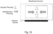
- hydrodynamic focused particle streams in microchannels, microfluidic chips, or other rectangular (or quasi-rectangular) channel geometrics can be enhanced by combining acoustic focusing and hydrodynamic focusing.
- one dimensional hydrodynamic focusing can be used, as illustrated in Fig. 10 .
- a combination acoustic and hydrodynamic focusing in a microfluidic channel is shown. Hydrodynamic focusing localizes particles in the horizontal direction and acoustic focusing localizes particles in the vertical direction.
- Another example allows for serial acoustic focusing in microfluidic applications.
- Acoustic focusing applied to a flowing stream of particles in a quasi-rectangular cross section chamber focuses particles into a ribbon-like structure.
- a method to focus particles into a narrow spatial configuration involves acoustically focusing particles into a plane, rotating the flow by 90 degrees, and then acoustically focusing again into the new orthogonal plane. The net result is a narrow spatial distribution of particles.
- the transducer is used to excite a dipole type mode within the flow chamber, the result is particles narrowly focused about the central axis of the flow chamber.
- bubbles that adhere to walls of a fluidic system are problematic. They can interfere by moving laminar flow lines, affecting local reactions, deviating focused particle streams.
- bubbles in a fluidic system can have the effect of moving the position of the hydrodynamically-focused sample stream. This movement appears as a misalignment of the optical system to the user and a recalibration is required.
- a technique to dislodge bubbles from nucleation sites in fluidic systems, especially microfluidic systems, is very desirable.
- Acoustic radiation pressure has been shown to have a large effect on bubbles in fluids due to the large mismatch in density and compressibility between liquids and gases. Acoustic energy can be used to dislodge bubbles from fluidic system in several different ways.
- a fluidic system is engineered such that when resonated at an appropriate acoustic frequency, bubbles experience a force that pulls them away from the wall and stabilizes their equilibrium position within the fluid stream that exists at the location of a pressure node (for bubbles driven at frequencies below their monopole resonance).
- the chamber is preferably driven acoustically with either an internal acoustic source or noninvasively with a source attached to an outer wall of the chamber. This is a robust method to dislodge bubbles from walls.
- vibration of the channel walls at low frequencies is preferably used to dislodge the bubbles.
- large surface displacements are achieved. (These displacements are typically larger at lower frequencies.)
- Large forces coupled with large displacements are preferably used to break the bond between the bubble and the chamber surface. The inertial forces coupled with localized fluid flows at the chamber wall surface are effective at bubble dislodgement.
- the transducer is preferably coupled to an outer wall of the flow chamber.
- the transducer can alternatively form a wall of the flow chamber.
- Another method of hydrodynamically and acoustically focusing particles provides an example of the present disclosure.
- This example preferably comprises providing a fluid comprising particles therein, flowing a sheath fluid into outer confines of a flow chamber, flowing the fluid containing the particles into a central core of the flow chamber, and applying acoustic radiation pressure to the fluid comprising the particles.
- This example can also comprise analyzing the particles.
- One example of the present disclosure comprises a method of aligning particles using acoustic radiation pressure.
- This example preferably includes providing a fluid comprising particles therein, subjecting the fluid to acoustic radiation pressure, rotating the fluid 90 degrees, and subjecting the fluid to acoustic radiation pressure a second time to align the particles.
- This example can also comprise analyzing the aligned particles.
- Another example of the present disclosure comprises a method of hydrodynamically and acoustically focusing particles in a fluid.
- This example includes flowing a fluid comprising particles therein, subjecting the fluid to acoustic radiation pressure in one planar direction to acoustically focus the particles, and flowing a sheath fluid in a second planar direction thereby hydrodynamically focusing the fluid in the second planar direction to further focus the particles.
- the present disclosure further includes methods for dislodging bubbles in a fluidic system. These methods comprise providing a fluid stream through a channel and resonating the channel at an acoustic frequency. These methods also include providing a fluid stream through a channel and vibrating the channel walls at a low frequency.
- Another example of the present disclosure comprises a method for acoustically focusing particles into a quasi-planar arrangement in a fluid comprising particles.
- the method preferably comprises flowing the fluid comprising particles therein through a flow chamber comprising an oblate cross-sectional geometry and subjecting the fluid to acoustic radiation pressure.
- the cross-sectional geometry of the flow chamber is preferably elliptical. This example can also include imaging the particles.
Landscapes
- Chemical & Material Sciences (AREA)
- Physics & Mathematics (AREA)
- General Health & Medical Sciences (AREA)
- Health & Medical Sciences (AREA)
- Biochemistry (AREA)
- Pathology (AREA)
- Immunology (AREA)
- General Physics & Mathematics (AREA)
- Dispersion Chemistry (AREA)
- Life Sciences & Earth Sciences (AREA)
- Analytical Chemistry (AREA)
- Acoustics & Sound (AREA)
- Multimedia (AREA)
- Engineering & Computer Science (AREA)
- Audiology, Speech & Language Pathology (AREA)
- Physical Or Chemical Processes And Apparatus (AREA)
- Investigating Or Analyzing Materials By The Use Of Ultrasonic Waves (AREA)
- Measurement Of Velocity Or Position Using Acoustic Or Ultrasonic Waves (AREA)
- Investigating, Analyzing Materials By Fluorescence Or Luminescence (AREA)
- Ultra Sonic Daignosis Equipment (AREA)
- Measuring Fluid Pressure (AREA)
- Powder Metallurgy (AREA)
Claims (15)
- Capillaire de focalisation acoustique comprenant :un capillaire (14) et au moins une source de vibrations (16) ;le capillaire (14) accouplé à l'au moins une source de vibrations (16) ; etl'au moins une source de vibrations (16) possède une rainure (18),l'au moins une source de vibrations (16) étant un générateur de vibrations capable de générer une vibration ou un déplacement de surface du capillaire (14) ;caractérisé en ce que le capillaire (14) a une section transversale aplatie, et ledit capillaire (14) étant accouplé à ladite source de vibrations (16) au niveau de ladite rainure (18).
- Capillaire de focalisation acoustique selon la revendication 1, ladite rainure (18) ayant une géométrie de section transversale approximativement identique à celle dudit capillaire (14).
- Capillaire de focalisation acoustique selon la revendication 1 ou la revendication 2, ledit capillaire étant elliptique.
- Capillaire de focalisation acoustique selon l'une quelconque des revendications précédentes, ladite source de vibrations (16) comprenant un matériau piézoélectrique.
- Capillaire de focalisation acoustique selon l'une quelconque des revendications précédentes, ladite rainure (18) augmentant une ouverture de source acoustique dudit capillaire.
- Appareil qui focalise acoustiquement des particules dans un agencement quasi planaire dans un fluide comprenant :un capillaire de focalisation acoustique selon la revendication 1 ; etladite au moins une source de vibration fournissant au moins un transducteur (16, 28, 30, 32, 34) accouplé au capillaire (14),le capillaire (14) étant bercé dans une source de vibrations rainurée (16).
- Appareil selon la revendication 6, ledit capillaire étant elliptique.
- Appareil selon la revendication 6 ou la revendication 7, comprenant en outre un imageur destiné à imager les particules.
- Procédé de fabrication d'un capillaire de focalisation acoustique comprenant :la fourniture d'un capillaire (14) ayant une section transversale aplatie et au moins une source de vibrations (16) ;l'ajustage d'une rainure (18) dans la source de vibrations (16) ; etl'accouplement de l'au moins une source de vibrations (16) au capillaire (14) au niveau de la rainure (18), l'au moins une source de vibrations (16) étant un générateur de vibrations capable de générer une vibration ou un déplacement de surface du capillaire (14).
- Procédé selon la revendication 9, la rainure (18) ayant une géométrie de section transversale approximativement identique à celle du capillaire (14).
- Procédé selon la revendication 9 ou la revendication 10, le capillaire étant elliptique.
- Procédé selon l'une quelconque des revendications 9 à 11, l'au moins une source de vibrations (16) comprenant un matériau piézoélectrique.
- Procédé selon l'une quelconque des revendications 9 à 12, comprenant en outre l'augmentation de l'ouverture de la source acoustique du capillaire.
- Procédé de focalisation hydrodynamique et acoustique d'un flux de particules comprenant :l'écoulement d'un fluide de gaine (24) dans les limites extérieures d'un capillaire (22) ;l'écoulement d'un courant de particules (20) dans un noyau central du capillaire (22) ; etl'application d'une pression de rayonnement acoustique au flux de particules à l'intérieur du fluide de gaine (24),le capillaire étant bercé dans une source de vibrations rainurée,le capillaire ayant une section transversale aplatie,et la source de vibrations étant un générateur de vibrations capable de générer une vibration oudéplacement de surface du capillaire.
- Procédé selon la revendication 14, le flux de particules étant focalisé hydrodynamiquement et ultérieurement focalisé acoustiquement, ou le flux de particules étant focalisé acoustiquement et focalisé hydrodynamiquement simultanément.
Applications Claiming Priority (3)
| Application Number | Priority Date | Filing Date | Title |
|---|---|---|---|
| US2144308P | 2008-01-16 | 2008-01-16 | |
| US12/209,084 US8714014B2 (en) | 2008-01-16 | 2008-09-11 | System and method for acoustic focusing hardware and implementations |
| PCT/US2009/031154 WO2009091925A2 (fr) | 2008-01-16 | 2009-01-15 | Système et procédé pour matériel de concentration acoustique et mises en œuvre |
Publications (2)
| Publication Number | Publication Date |
|---|---|
| EP2240927A2 EP2240927A2 (fr) | 2010-10-20 |
| EP2240927B1 true EP2240927B1 (fr) | 2021-07-21 |
Family
ID=40849627
Family Applications (1)
| Application Number | Title | Priority Date | Filing Date |
|---|---|---|---|
| EP09701876.6A Active EP2240927B1 (fr) | 2008-01-16 | 2009-01-15 | Systeme et procede pour materiel de concentration acoustique et mise en oeuvre |
Country Status (13)
| Country | Link |
|---|---|
| US (5) | US8714014B2 (fr) |
| EP (1) | EP2240927B1 (fr) |
| JP (4) | JP5364725B2 (fr) |
| KR (3) | KR101604145B1 (fr) |
| CN (3) | CN101971247A (fr) |
| AU (1) | AU2009206101B2 (fr) |
| BR (1) | BRPI0906520A2 (fr) |
| CA (1) | CA2710024C (fr) |
| EA (1) | EA021093B9 (fr) |
| IL (1) | IL206560A0 (fr) |
| SG (1) | SG193165A1 (fr) |
| WO (1) | WO2009091925A2 (fr) |
| ZA (1) | ZA201005045B (fr) |
Families Citing this family (104)
| Publication number | Priority date | Publication date | Assignee | Title |
|---|---|---|---|---|
| AU2004285960A1 (en) | 2003-10-30 | 2005-05-12 | Cytonome/St, Llc | Multilayer hydrodynamic sheath flow structure |
| US7340957B2 (en) | 2004-07-29 | 2008-03-11 | Los Alamos National Security, Llc | Ultrasonic analyte concentration and application in flow cytometry |
| US7835000B2 (en) | 2006-11-03 | 2010-11-16 | Los Alamos National Security, Llc | System and method for measuring particles in a sample stream of a flow cytometer or the like |
| ATE538377T1 (de) | 2007-04-02 | 2012-01-15 | Acoustic Cytometry Systems Inc | Verfahren zur verbesserten analyse von in einem akustischen feld fokussierten zellen und partikeln |
| US8083068B2 (en) | 2007-04-09 | 2011-12-27 | Los Alamos National Security, Llc | Apparatus for separating particles utilizing engineered acoustic contrast capture particles |
| US7837040B2 (en) * | 2007-04-09 | 2010-11-23 | Los Alamos National Security, Llc | Acoustic concentration of particles in fluid flow |
| US8528406B2 (en) * | 2007-10-24 | 2013-09-10 | Los Alamos National Security, LLP | Method for non-contact particle manipulation and control of particle spacing along an axis |
| US8263407B2 (en) * | 2007-10-24 | 2012-09-11 | Los Alamos National Security, Llc | Method for non-contact particle manipulation and control of particle spacing along an axis |
| US8266950B2 (en) * | 2007-12-19 | 2012-09-18 | Los Alamos National Security, LLP | Particle analysis in an acoustic cytometer |
| US8714014B2 (en) | 2008-01-16 | 2014-05-06 | Life Technologies Corporation | System and method for acoustic focusing hardware and implementations |
| US8479567B2 (en) * | 2009-02-02 | 2013-07-09 | Technion Research & Development Foundation Limited | Device and method of particle focusing |
| US8691145B2 (en) | 2009-11-16 | 2014-04-08 | Flodesign Sonics, Inc. | Ultrasound and acoustophoresis for water purification |
| JP5887275B2 (ja) * | 2009-12-04 | 2016-03-16 | ライフ テクノロジーズ コーポレーション | アコースティックフローサイトメトリーのための装置、システム、方法、およびコンピュータ読み取り可能な媒体 |
| AU2015224429B2 (en) * | 2009-12-04 | 2017-05-25 | Life Technologies Corporation | Apparatuses, systems, methods, and computer readable media for acoustic flow cytometry |
| US20110278218A1 (en) * | 2010-04-12 | 2011-11-17 | Flodesign Sonics, Inc. | Ultrasound and Acoustophoresis Technology for Separation of Oil and Water, with Application to Produce Water |
| EP2582631A4 (fr) | 2010-06-16 | 2016-05-25 | Flodesign Sonics Inc | Système de dessalement à cristal phononique et méthode d'utilisation |
| US9421553B2 (en) * | 2010-08-23 | 2016-08-23 | Flodesign Sonics, Inc. | High-volume fast separation of multi-phase components in fluid suspensions |
| US8679338B2 (en) | 2010-08-23 | 2014-03-25 | Flodesign Sonics, Inc. | Combined acoustic micro filtration and phononic crystal membrane particle separation |
| AU2011295660B2 (en) * | 2010-09-03 | 2015-10-01 | Los Alamos National Security, Llc | Integrated acoustic phase separator and multiphase fluid composition monitoring apparatus and method |
| EP4534131A3 (fr) | 2010-09-30 | 2025-05-21 | ResMed Pty Ltd | Systèmes d'interface patient |
| AU2011308095B2 (en) | 2010-09-30 | 2014-10-09 | Resmed Limited | Mask system |
| USD698038S1 (en) | 2011-03-03 | 2014-01-21 | Life Technologies Corporation | Plate loader |
| JP5973471B2 (ja) | 2011-03-03 | 2016-08-23 | ライフ テクノロジーズ コーポレーション | サンプリングプローブ、システム、装置、および方法 |
| WO2012135667A1 (fr) | 2011-04-01 | 2012-10-04 | Life Technologies Corporation | Système et méthode de détermination du nombre de copies par volume unitaire en utilisant la pcr et la régulation de débit de gouttelettes |
| US8528582B2 (en) * | 2011-04-28 | 2013-09-10 | The United States Of America As Represented By The Secretary Of The Navy | Method of changing fluid flow by using an optical beam |
| WO2013003498A2 (fr) | 2011-06-27 | 2013-01-03 | Life Technologies Corporation | Procédés et protocoles de cytométrie acoustique |
| US9656263B2 (en) | 2011-09-28 | 2017-05-23 | Acousort Ab | System and method to separate cells and/or particles |
| US10689609B2 (en) | 2012-03-15 | 2020-06-23 | Flodesign Sonics, Inc. | Acoustic bioreactor processes |
| US9458450B2 (en) | 2012-03-15 | 2016-10-04 | Flodesign Sonics, Inc. | Acoustophoretic separation technology using multi-dimensional standing waves |
| US9272234B2 (en) | 2012-03-15 | 2016-03-01 | Flodesign Sonics, Inc. | Separation of multi-component fluid through ultrasonic acoustophoresis |
| US10967298B2 (en) | 2012-03-15 | 2021-04-06 | Flodesign Sonics, Inc. | Driver and control for variable impedence load |
| US9416344B2 (en) | 2012-03-15 | 2016-08-16 | Flodesign Sonics, Inc. | Bioreactor using acoustic standing waves |
| US9745548B2 (en) | 2012-03-15 | 2017-08-29 | Flodesign Sonics, Inc. | Acoustic perfusion devices |
| US9340435B2 (en) | 2012-03-15 | 2016-05-17 | Flodesign Sonics, Inc. | Separation of multi-component fluid through ultrasonic acoustophoresis |
| US10370635B2 (en) | 2012-03-15 | 2019-08-06 | Flodesign Sonics, Inc. | Acoustic separation of T cells |
| US9783775B2 (en) | 2012-03-15 | 2017-10-10 | Flodesign Sonics, Inc. | Bioreactor using acoustic standing waves |
| US10953436B2 (en) | 2012-03-15 | 2021-03-23 | Flodesign Sonics, Inc. | Acoustophoretic device with piezoelectric transducer array |
| US10040011B2 (en) | 2012-03-15 | 2018-08-07 | Flodesign Sonics, Inc. | Acoustophoretic multi-component separation technology platform |
| US9950282B2 (en) | 2012-03-15 | 2018-04-24 | Flodesign Sonics, Inc. | Electronic configuration and control for acoustic standing wave generation |
| US9623348B2 (en) | 2012-03-15 | 2017-04-18 | Flodesign Sonics, Inc. | Reflector for an acoustophoretic device |
| US9822333B2 (en) | 2012-03-15 | 2017-11-21 | Flodesign Sonics, Inc. | Acoustic perfusion devices |
| US9752113B2 (en) | 2012-03-15 | 2017-09-05 | Flodesign Sonics, Inc. | Acoustic perfusion devices |
| US9422328B2 (en) | 2012-03-15 | 2016-08-23 | Flodesign Sonics, Inc. | Acoustic bioreactor processes |
| US9688958B2 (en) | 2012-03-15 | 2017-06-27 | Flodesign Sonics, Inc. | Acoustic bioreactor processes |
| US9796956B2 (en) | 2013-11-06 | 2017-10-24 | Flodesign Sonics, Inc. | Multi-stage acoustophoresis device |
| US9752114B2 (en) | 2012-03-15 | 2017-09-05 | Flodesign Sonics, Inc | Bioreactor using acoustic standing waves |
| US10704021B2 (en) | 2012-03-15 | 2020-07-07 | Flodesign Sonics, Inc. | Acoustic perfusion devices |
| US10322949B2 (en) | 2012-03-15 | 2019-06-18 | Flodesign Sonics, Inc. | Transducer and reflector configurations for an acoustophoretic device |
| US9567559B2 (en) | 2012-03-15 | 2017-02-14 | Flodesign Sonics, Inc. | Bioreactor using acoustic standing waves |
| US10737953B2 (en) | 2012-04-20 | 2020-08-11 | Flodesign Sonics, Inc. | Acoustophoretic method for use in bioreactors |
| US11324873B2 (en) | 2012-04-20 | 2022-05-10 | Flodesign Sonics, Inc. | Acoustic blood separation processes and devices |
| NZ711384A (en) * | 2013-03-14 | 2018-06-29 | Cytonome St Llc | Hydrodynamic focusing apparatus and methods |
| US9279750B2 (en) | 2013-03-15 | 2016-03-08 | Iris International, Inc. | Method and composition for staining and sample processing |
| WO2014210046A1 (fr) | 2013-06-24 | 2014-12-31 | Flodesign Sonics, Inc. | Séparateur sonique par la dynamique des fluides |
| US9745569B2 (en) | 2013-09-13 | 2017-08-29 | Flodesign Sonics, Inc. | System for generating high concentration factors for low cell density suspensions |
| WO2015105955A1 (fr) | 2014-01-08 | 2015-07-16 | Flodesign Sonics, Inc. | Dispositif d'acoustophorèse avec double chambre acoustophorétique |
| CA2948355A1 (fr) | 2014-05-08 | 2015-11-12 | Bart Lipkens | Dispositif d'acoustophorese comprenant un ensemble de transducteurs piezoelectriques |
| US9827511B2 (en) | 2014-07-02 | 2017-11-28 | Flodesign Sonics, Inc. | Acoustophoretic device with uniform fluid flow |
| US9744483B2 (en) | 2014-07-02 | 2017-08-29 | Flodesign Sonics, Inc. | Large scale acoustic separation device |
| JP6104475B2 (ja) * | 2014-08-28 | 2017-04-05 | シスメックス株式会社 | 粒子撮像装置および粒子撮像方法 |
| CN106794393A (zh) | 2014-09-30 | 2017-05-31 | 弗洛设计声能学公司 | 含颗粒的非流动流体的声泳净化 |
| CN106796169B (zh) * | 2014-10-01 | 2021-01-15 | 水光科技私人有限公司 | 探测流体中颗粒的传感器 |
| EP3209402B1 (fr) | 2014-10-24 | 2019-11-20 | Life Technologies Corporation | Système de purification d'échantillon liquide-liquide à décantation acoustique |
| US10106770B2 (en) | 2015-03-24 | 2018-10-23 | Flodesign Sonics, Inc. | Methods and apparatus for particle aggregation using acoustic standing waves |
| US10737012B2 (en) | 2015-03-31 | 2020-08-11 | Biomet Biologics, Inc. | Cell washing using acoustic waves |
| US9855382B2 (en) * | 2015-03-31 | 2018-01-02 | Biomet Biologics, Llc | Cell washing device using standing acoustic waves and a phantom material |
| US11021699B2 (en) | 2015-04-29 | 2021-06-01 | FioDesign Sonics, Inc. | Separation using angled acoustic waves |
| US11708572B2 (en) | 2015-04-29 | 2023-07-25 | Flodesign Sonics, Inc. | Acoustic cell separation techniques and processes |
| WO2016176663A1 (fr) | 2015-04-29 | 2016-11-03 | Flodesign Sonics, Inc. | Dispositif acoustophorétique pour déviation de particules à onde angulaire |
| US11377651B2 (en) | 2016-10-19 | 2022-07-05 | Flodesign Sonics, Inc. | Cell therapy processes utilizing acoustophoresis |
| KR102341153B1 (ko) * | 2015-05-13 | 2021-12-17 | 가부시키가이샤 에아렉크스 | 파티클 제어 방법 |
| CA2986238A1 (fr) | 2015-05-20 | 2016-11-24 | Bart Lipkens | Manipulation acoustique de particules dans des champs d'ondes stationnaires |
| US10161926B2 (en) | 2015-06-11 | 2018-12-25 | Flodesign Sonics, Inc. | Acoustic methods for separation of cells and pathogens |
| US9663756B1 (en) | 2016-02-25 | 2017-05-30 | Flodesign Sonics, Inc. | Acoustic separation of cellular supporting materials from cultured cells |
| JP6911021B2 (ja) | 2015-06-25 | 2021-07-28 | サイトノーム/エスティー・エルエルシー | 音響操作を用いるマイクロ流体デバイスおよびシステム |
| CN105149019B (zh) * | 2015-06-29 | 2017-04-19 | 清华大学 | 用于二维流体动力聚焦的微流道结构和微流体芯片 |
| EP3319739B1 (fr) | 2015-07-09 | 2021-03-31 | Flodesign Sonics Inc. | Cristaux piézoélectriques et réflecteurs non plans et non symétriques |
| US11459540B2 (en) | 2015-07-28 | 2022-10-04 | Flodesign Sonics, Inc. | Expanded bed affinity selection |
| US11474085B2 (en) | 2015-07-28 | 2022-10-18 | Flodesign Sonics, Inc. | Expanded bed affinity selection |
| WO2017054839A1 (fr) * | 2015-09-28 | 2017-04-06 | Siemens Healthcare Gmbh | Technique d'alignement d'une entité biologique non sphérique dans une cuve à circulation |
| HUE061715T2 (hu) * | 2015-12-23 | 2023-08-28 | Siemens Healthcare Gmbh | Áramlási cella részecskék elemzéséhez egy vizsgálni kívánt folyadékban, eljárás és alkalmazás |
| CN105854963B (zh) * | 2016-04-06 | 2017-11-21 | 清华大学 | 利用单路鞘液实现二维流体动力聚焦的微流道结构和微流体芯片 |
| US10710006B2 (en) | 2016-04-25 | 2020-07-14 | Flodesign Sonics, Inc. | Piezoelectric transducer for generation of an acoustic standing wave |
| WO2017192760A1 (fr) | 2016-05-03 | 2017-11-09 | Flodesign Sonics, Inc. | Lavage, concentration et séparation de cellules thérapeutiques par acoustophorèse |
| US11214789B2 (en) | 2016-05-03 | 2022-01-04 | Flodesign Sonics, Inc. | Concentration and washing of particles with acoustics |
| US11085035B2 (en) | 2016-05-03 | 2021-08-10 | Flodesign Sonics, Inc. | Therapeutic cell washing, concentration, and separation utilizing acoustophoresis |
| CA3041517A1 (fr) | 2016-10-19 | 2018-04-26 | Flodesign Sonics, Inc. | Extraction par affinite de cellules par un procede acoustique |
| CN106872339A (zh) * | 2017-01-10 | 2017-06-20 | 中国科学院苏州生物医学工程技术研究所 | 一种粒子排序方法及其装置和用途 |
| US20180213340A1 (en) * | 2017-01-26 | 2018-07-26 | W. L. Gore & Associates, Inc. | High throughput acoustic vent structure test apparatus |
| EP3602003B1 (fr) | 2017-03-31 | 2026-04-22 | Life Technologies Corporation | Appareil, système et procédé pour cytométrie de flux par imagerie |
| RU174330U1 (ru) * | 2017-04-27 | 2017-10-11 | Федеральное государственное бюджетное образовательное учреждение высшего образования "Сибирский государственный университет геосистем и технологий" (СГУГиТ) | Акустическая ловушка в поле стоячей волны на основе двух встречных пучков |
| WO2019118921A1 (fr) | 2017-12-14 | 2019-06-20 | Flodesign Sonics, Inc. | Circuit d'excitation et circuit de commande de transducteur acoustique |
| CN111565787A (zh) * | 2018-03-09 | 2020-08-21 | 弗洛设计声能学公司 | 用于转染和转导的声学方法 |
| US12111243B2 (en) * | 2020-01-14 | 2024-10-08 | Foss Analytical A/S | Hydrodynamic focusing device |
| CN111154623A (zh) * | 2020-02-21 | 2020-05-15 | 北京化工大学 | 一种带振动功能的便携式对流pcr扩增检测装置 |
| WO2021184121A1 (fr) * | 2020-03-18 | 2021-09-23 | Alejandro Martinez | Système et procédé de dépôt par énergie orientée à l'aide d'un champ sonore |
| EP3978097B1 (fr) * | 2020-08-04 | 2024-09-25 | Beihang University | Dispositif de séparation de particules submicrométriques dans l'air |
| WO2022187608A1 (fr) * | 2021-03-05 | 2022-09-09 | Nanocellect Biomedical, Inc. | Systèmes et procédés de concentration de populations de cellules triées |
| EP4330652A1 (fr) * | 2021-04-27 | 2024-03-06 | Life Technologies Corporation | Centrage de flux d'échantillon |
| CN114932751B (zh) * | 2022-06-08 | 2023-04-14 | 西北工业大学 | 一种超声聚焦喷印气溶胶油墨颗粒的装置及方法 |
| CN116531806A (zh) * | 2023-05-09 | 2023-08-04 | 广东工业大学 | 一种利用声流体效应操控悬浮颗粒快速沉降的装置及方法 |
| KR102917551B1 (ko) * | 2023-06-05 | 2026-01-23 | 중앙대학교 산학협력단 | 유동물 거동 통제 장치 및 유동물 거동 통제 방법 |
| WO2025123040A1 (fr) | 2023-12-08 | 2025-06-12 | Life Technologies Corporation | Indicateurs de porte hors tracé et outils de navigation pour analyse de données de cellules |
| US12584902B2 (en) | 2023-12-10 | 2026-03-24 | Instrumentation Laboratory Company | Acoustic separation of a test sample |
Citations (2)
| Publication number | Priority date | Publication date | Assignee | Title |
|---|---|---|---|---|
| US4991923A (en) * | 1989-01-17 | 1991-02-12 | Board Of Trustees Of The Leland Stanford Junior University | Acousto-optic modulator for optical fibers using Hertzian contact with a grooved transducer substrate |
| JP2007285908A (ja) * | 2006-04-18 | 2007-11-01 | Matsushita Electric Ind Co Ltd | 成分分離デバイスと、この成分分離デバイスを用いた化学分析デバイス |
Family Cites Families (173)
| Publication number | Priority date | Publication date | Assignee | Title |
|---|---|---|---|---|
| GB500271A (en) | 1936-05-04 | 1939-02-06 | Metallgesellschaft Ag | Process of and apparatus for clarifying liquids |
| US2900536A (en) * | 1954-11-18 | 1959-08-18 | Astatic Corp | Design of electro-mechanical transducer elements |
| US3673872A (en) * | 1966-02-01 | 1972-07-04 | Atomic Energy Commission | Cryogenic sound supported inertial reference |
| US3882732A (en) * | 1973-08-31 | 1975-05-13 | Nasa | Material suspension within an acoustically excited resonant chamber |
| US4055491A (en) | 1976-06-02 | 1977-10-25 | Porath Furedi Asher | Apparatus and method for removing fine particles from a liquid medium by ultrasonic waves |
| CA1142466A (fr) | 1979-01-09 | 1983-03-08 | National Research Development Corporation | Lignees cellulaires |
| US4265124A (en) * | 1979-06-04 | 1981-05-05 | Rockwell International Corporation | Remote acoustic wave sensors |
| US4285810A (en) * | 1980-02-29 | 1981-08-25 | E. I. Du Pont De Nemours And Company | Method and apparatus for field flow fractionation |
| DE3027433A1 (de) | 1980-07-19 | 1982-02-18 | Messerschmitt-Bölkow-Blohm GmbH, 8000 München | Verfahren zur trennung von gemischen |
| US4523982A (en) * | 1981-03-05 | 1985-06-18 | The Dow Chemical Company | Electron rich aromatics as cure promoters for radiation curable compositions |
| US4434230A (en) * | 1981-08-12 | 1984-02-28 | Research Corporation | Human nonsecretory plasmacytoid cell line |
| US4523682A (en) * | 1982-05-19 | 1985-06-18 | The United States Of America As Represented By The Administrator Of The National Aeronautics And Space Administration | Acoustic particle separation |
| US4492752A (en) * | 1982-09-03 | 1985-01-08 | Ortho Diagnostics Systems Inc. | Method for discriminating between unstained and absorbing dye stained cells |
| DE3481281D1 (de) * | 1983-10-31 | 1990-03-15 | Nat Res Dev | Beeinflussung von partikeln. |
| US4549435A (en) * | 1983-12-14 | 1985-10-29 | The United States Of America As Represented By The United States National Aeronautics And Space Administration | Vibrating-chamber levitation systems |
| GB8417240D0 (en) * | 1984-07-06 | 1984-08-08 | Unilever Plc | Particle separation |
| US4604542A (en) * | 1984-07-25 | 1986-08-05 | Gould Inc. | Broadband radial vibrator transducer with multiple resonant frequencies |
| IT1176731B (it) * | 1984-09-20 | 1987-08-18 | Anic Spa | Promotori di adesione per substrati metallici |
| JPS61161744U (fr) * | 1985-03-29 | 1986-10-07 | ||
| JPS61223650A (ja) * | 1985-03-29 | 1986-10-04 | Shimadzu Corp | 生物試料の構成要素の分取装置 |
| US5800861A (en) | 1985-08-15 | 1998-09-01 | The Sherwin-Williams Company | High solid infrared absorbing compositions |
| US4759775A (en) * | 1986-02-21 | 1988-07-26 | Utah Bioresearch, Inc. | Methods and apparatus for moving and separating materials exhibiting different physical properties |
| GB8612759D0 (en) | 1986-05-27 | 1986-07-02 | Unilever Plc | Manipulating particulate matter |
| JPS63139231A (ja) | 1986-07-18 | 1988-06-11 | Akira Mizuno | 液体中の微粒子測定方法 |
| US5346670A (en) | 1986-12-24 | 1994-09-13 | British Technology Group U.S.A. Inc. | Phthalocyanine and tetrabenztriazaporphyrin reagents |
| JPS63262565A (ja) * | 1987-04-20 | 1988-10-28 | Hitachi Ltd | フロ−セル |
| AT389235B (de) | 1987-05-19 | 1989-11-10 | Stuckart Wolfgang | Verfahren zur reinigung von fluessigkeiten mittels ultraschall und vorrichtungen zur durchfuehrung dieses verfahrens |
| JPS63307332A (ja) * | 1987-06-08 | 1988-12-15 | Hitachi Ltd | 光計測式生体細胞分析装置 |
| JPH01112161A (ja) | 1987-07-20 | 1989-04-28 | Hitachi Ltd | 免疫凝集定量装置 |
| US4913883A (en) * | 1987-07-20 | 1990-04-03 | Hitachi, Ltd. | Particle agglutination immunoassay apparatus |
| US4777823A (en) | 1987-08-20 | 1988-10-18 | The United States Of America As Represented By The Administrator Of The National Aeronautics And Space Administration | Controlled sample orientation and rotation in an acoustic levitator |
| GB8724067D0 (en) * | 1987-10-14 | 1987-11-18 | Unilever Plc | Manipulating particles |
| US4845025A (en) * | 1987-11-10 | 1989-07-04 | Coulter Corporation | Biological sample mixing apparatus and method |
| US5040890A (en) * | 1987-11-25 | 1991-08-20 | Becton, Dickinson And Company | Sheathed particle flow controlled by differential pressure |
| US4987086A (en) * | 1987-11-30 | 1991-01-22 | Becton, Dickinson And Company | Method for analysis of subpopulations of cells |
| US4867559A (en) | 1988-01-06 | 1989-09-19 | Amoco Corporation | Liquid/liquid fiber-optic fluorescence detector and absorbance analyzer |
| US4994923A (en) * | 1988-02-05 | 1991-02-19 | Hitachi, Ltd. | Video signal recording and reproducing apparatus with signal processing circuit for improvement of picture quality |
| JPH0718785B2 (ja) * | 1988-09-19 | 1995-03-06 | 株式会社日立製作所 | フローセル装置 |
| AT390739B (de) * | 1988-11-03 | 1990-06-25 | Ewald Dipl Ing Dr Benes | Verfahren und einrichtung zur separation von teilchen, welche in einem dispersionsmittel dispergiert sind |
| US4964303A (en) | 1988-11-15 | 1990-10-23 | The United States Of America As Represented By The Administrator Of The National Aeronautics And Space Administration | Acoustic positioning and orientation prediction |
| US5032381A (en) * | 1988-12-20 | 1991-07-16 | Tropix, Inc. | Chemiluminescence-based static and flow cytometry |
| US4979824A (en) | 1989-05-26 | 1990-12-25 | Board Of Trustees Of The Leland Stanford Junior University | High sensitivity fluorescent single particle and single molecule detection apparatus and method |
| US5030002A (en) * | 1989-08-11 | 1991-07-09 | Becton, Dickinson And Company | Method and apparatus for sorting particles with a moving catcher tube |
| US5085783A (en) * | 1990-08-16 | 1992-02-04 | Case Western Reserve University | Acoustically driven particle separation method and apparatus |
| US5504337A (en) * | 1990-10-10 | 1996-04-02 | Joseph R. Lakowicz | Method and apparatus for performing phase fluorescence lifetime measurements in flow cytometry |
| JP2965688B2 (ja) * | 1990-11-30 | 1999-10-18 | シスメックス株式会社 | 粒子検出装置 |
| US5221258A (en) * | 1991-01-22 | 1993-06-22 | Shturman Technologies, Inc. | Introduction balloon catheter |
| US5376551A (en) | 1991-03-12 | 1994-12-27 | University Of Utah Research Foundation | Apparatus for using fluorescently labeled ligands in studying interaction of a native ligand and its receptor |
| US5674698A (en) | 1992-09-14 | 1997-10-07 | Sri International | Up-converting reporters for biological and other assays using laser excitation techniques |
| JP3488732B2 (ja) * | 1992-12-02 | 2004-01-19 | 株式会社日立製作所 | 超音波処理装置 |
| US6216538B1 (en) * | 1992-12-02 | 2001-04-17 | Hitachi, Ltd. | Particle handling apparatus for handling particles in fluid by acoustic radiation pressure |
| US5395588A (en) * | 1992-12-14 | 1995-03-07 | Becton Dickinson And Company | Control of flow cytometer having vacuum fluidics |
| US5430541A (en) * | 1993-01-12 | 1995-07-04 | Applied Biosystems Inc. | High efficiency fluorescence flow cell for capillary liquid chromatography or capillary electrophoresis |
| JP3205413B2 (ja) * | 1993-02-15 | 2001-09-04 | 株式会社日立製作所 | 微粒子計測装置及び微粒子計測方法 |
| US5547849A (en) * | 1993-02-17 | 1996-08-20 | Biometric Imaging, Inc. | Apparatus and method for volumetric capillary cytometry |
| AU684284B2 (en) * | 1993-05-11 | 1997-12-11 | Sonosep Biotech, Inc. | Multilayered piezoelectric resonator for the separation of suspended particles |
| AT398707B (de) * | 1993-05-11 | 1995-01-25 | Trampler Felix | Mehrschichtiger piezoelektrischer resonator für die separation von suspendierten teilchen |
| NO932088L (no) * | 1993-06-08 | 1995-01-05 | Oddbjoern Gjelsnes | Anordning for anvendelse ved væskeströmscytometri |
| US5626767A (en) * | 1993-07-02 | 1997-05-06 | Sonosep Biotech Inc. | Acoustic filter for separating and recycling suspended particles |
| US5491344A (en) * | 1993-12-01 | 1996-02-13 | Tufts University | Method and system for examining the composition of a fluid or solid sample using fluorescence and/or absorption spectroscopy |
| JPH07286953A (ja) * | 1994-04-19 | 1995-10-31 | Toa Medical Electronics Co Ltd | イメージングフローサイトメータ |
| JP3260550B2 (ja) * | 1994-05-27 | 2002-02-25 | 株式会社日立製作所 | 微粒子分析装置 |
| JPH08266891A (ja) * | 1995-04-03 | 1996-10-15 | Hitachi Ltd | 微粒子取扱装置 |
| US5528045A (en) * | 1995-04-06 | 1996-06-18 | Becton Dickinson And Company | Particle analyzer with spatially split wavelength filter |
| JPH08297121A (ja) * | 1995-04-26 | 1996-11-12 | Hitachi Ltd | 粒子分析装置 |
| WO1997002482A1 (fr) * | 1995-06-30 | 1997-01-23 | Biometric Imaging, Inc. | Procede et dispositif pour la quantification volumetrique |
| US5798222A (en) * | 1995-07-17 | 1998-08-25 | Guava Technologies, Inc. | Apparatus for monitoring substances in organisms |
| US5981180A (en) | 1995-10-11 | 1999-11-09 | Luminex Corporation | Multiplexed analysis of clinical specimens apparatus and methods |
| JP3487699B2 (ja) | 1995-11-08 | 2004-01-19 | 株式会社日立製作所 | 超音波処理方法および装置 |
| JP2700058B2 (ja) | 1996-01-23 | 1998-01-19 | 工業技術院長 | 超音波を用いた非接触マイクロマニピュレーション方法 |
| US5688406A (en) | 1996-02-28 | 1997-11-18 | The United States Of America As Represented By The Secretary Of The Navy | Method and apparatus for separating particulate from a flowing fluid |
| US6221258B1 (en) | 1996-06-14 | 2001-04-24 | Case Western Reserve University | Method and apparatus for acoustically driven media filtration |
| US6055859A (en) * | 1996-10-01 | 2000-05-02 | Agency Of Industrial Science And Technology | Non-contact micromanipulation method and apparatus |
| GB9708984D0 (en) | 1997-05-03 | 1997-06-25 | Univ Cardiff | Particle manipulation |
| US6710871B1 (en) | 1997-06-09 | 2004-03-23 | Guava Technologies, Inc. | Method and apparatus for detecting microparticles in fluid samples |
| PE48299A1 (es) * | 1997-06-11 | 1999-07-06 | Nalco Chemical Co | Fluorometro de estado solido y metodos de uso para el mismo |
| JPH1114533A (ja) * | 1997-06-19 | 1999-01-22 | Hitachi Ltd | 微粒子形状測定装置 |
| US6074879A (en) * | 1997-06-23 | 2000-06-13 | Bayer Corporation | Synthetic polymer particles for use as standards and calibrators in flow cytometry |
| US6029518A (en) * | 1997-09-17 | 2000-02-29 | The United States Of America As Represented By The Administrator Of The National Aeronautics And Space Administration | Manipulation of liquids using phased array generation of acoustic radiation pressure |
| US6003388A (en) | 1997-09-17 | 1999-12-21 | The United States Of America As Represented By The Administrator Of The National Aeronautics And Space Administration | System for manipulating drops and bubbles using acoustic radiation pressure |
| KR20010041113A (ko) * | 1998-02-20 | 2001-05-15 | 헤릭호프, 리사 | 분류용 플로우 사이토미터의 진동시스템 |
| US6248590B1 (en) * | 1998-02-27 | 2001-06-19 | Cytomation, Inc. | Method and apparatus for flow cytometry |
| CA2320296A1 (fr) | 1998-05-18 | 1999-11-25 | University Of Washington | Cartouche d'analyse liquide |
| JPH11352048A (ja) * | 1998-06-04 | 1999-12-24 | Toray Eng Co Ltd | 液中微粒子測定装置 |
| GB2369308B (en) * | 1998-07-22 | 2002-11-06 | Protasis Uk Ltd | Particle manipulation device |
| US6090295A (en) * | 1998-08-11 | 2000-07-18 | University Technology Corporation | Method and apparatus for acoustically demixing aqueous solutions |
| US6197593B1 (en) * | 1998-10-20 | 2001-03-06 | Coulter International Corp. | Method for enumerating blood cells |
| US20010006416A1 (en) * | 1999-01-11 | 2001-07-05 | Johnson Paul E. | Ribbon flow cytometry apparatus and methods |
| WO2000041794A1 (fr) | 1999-01-15 | 2000-07-20 | University College Cardiff Consultants Ltd. | Manipulation de particules |
| US6975400B2 (en) * | 1999-01-25 | 2005-12-13 | Amnis Corporation | Imaging and analyzing parameters of small moving objects such as cells |
| US6565727B1 (en) * | 1999-01-25 | 2003-05-20 | Nanolytics, Inc. | Actuators for microfluidics without moving parts |
| US6337465B1 (en) * | 1999-03-09 | 2002-01-08 | Mide Technology Corp. | Laser machining of electroactive ceramics |
| CN1181337C (zh) * | 2000-08-08 | 2004-12-22 | 清华大学 | 微流体系统中实体分子的操纵方法及相关试剂盒 |
| JP2000298092A (ja) * | 1999-04-13 | 2000-10-24 | Horiba Ltd | 液中微粒子測定装置 |
| US6592821B1 (en) * | 1999-05-17 | 2003-07-15 | Caliper Technologies Corp. | Focusing of microparticles in microfluidic systems |
| US6309886B1 (en) | 1999-06-04 | 2001-10-30 | The Regents Of The University Of California | High throughput analysis of samples in flowing liquid |
| JP3306029B2 (ja) * | 1999-07-27 | 2002-07-24 | サーパス工業株式会社 | 超音波流量計及びその製造方法 |
| US6348687B1 (en) * | 1999-09-10 | 2002-02-19 | Sandia Corporation | Aerodynamic beam generator for large particles |
| US6449563B1 (en) | 1999-10-12 | 2002-09-10 | Dispersion Technology, Inc | Method and device for determining particle size distribution and zeta potential in concentrated dispersions |
| US6813017B1 (en) | 1999-10-20 | 2004-11-02 | Becton, Dickinson And Company | Apparatus and method employing incoherent light emitting semiconductor devices as particle detection light sources in a flow cytometer |
| US6263745B1 (en) | 1999-12-03 | 2001-07-24 | Xy, Inc. | Flow cytometer nozzle and flow cytometer sample handling methods |
| US6373567B1 (en) * | 1999-12-17 | 2002-04-16 | Micron Optical Systems | Dispersive near-IR Raman spectrometer |
| US6549275B1 (en) * | 2000-08-02 | 2003-04-15 | Honeywell International Inc. | Optical detection system for flow cytometry |
| US7262838B2 (en) | 2001-06-29 | 2007-08-28 | Honeywell International Inc. | Optical detection system for flow cytometry |
| US7978329B2 (en) | 2000-08-02 | 2011-07-12 | Honeywell International Inc. | Portable scattering and fluorescence cytometer |
| CN2448829Y (zh) * | 2000-09-29 | 2001-09-19 | 何永智 | 除垢防垢节能器 |
| CN100495030C (zh) * | 2000-09-30 | 2009-06-03 | 清华大学 | 多力操纵装置及其应用 |
| CN1221309C (zh) * | 2000-09-30 | 2005-10-05 | 清华大学 | 利用声场力和其它作用力对微粒进行场流分离的装置和方法 |
| US6736904B2 (en) | 2001-03-02 | 2004-05-18 | Paper Quality Management Associates | Method and apparatus for the generation of ultrasonic energy fields within circular structures containing a liquid |
| DE10111392A1 (de) | 2001-03-09 | 2002-09-12 | Chromeon Gmbh | Bioanalytisches Messverfahren unter Verwendung von Oxidasen |
| SE522801C2 (sv) * | 2001-03-09 | 2004-03-09 | Erysave Ab | Anordning för att separera suspenderade partiklar från en fluid med ultraljud samt metod för sådan separering |
| SE0103013D0 (sv) | 2001-03-09 | 2001-09-12 | Erysave Ab Ideon | System and method for treatment of whole blood |
| SE0100820D0 (sv) | 2001-03-09 | 2001-03-09 | Erysave Ab Ideon | Particle separation using an acoustic filter |
| US6467350B1 (en) | 2001-03-15 | 2002-10-22 | The Regents Of The University Of California | Cylindrical acoustic levitator/concentrator |
| DE60218074T2 (de) * | 2001-03-29 | 2008-02-07 | Sysmex Corp. | Durchflusszytometer |
| US6683314B2 (en) * | 2001-08-28 | 2004-01-27 | Becton, Dickinson And Company | Fluorescence detection instrument with reflective transfer legs for color decimation |
| WO2003027027A1 (fr) * | 2001-09-25 | 2003-04-03 | P.M.G. Medica Ltd. | Systeme et procede de sterilisation d'un liquide |
| US6773556B1 (en) * | 2001-10-18 | 2004-08-10 | Seagate Technology Llc | Method for energy barrier equalization of magnetic recording media and media obtained thereby |
| US6831279B2 (en) * | 2001-11-27 | 2004-12-14 | Her Majesty The Queen In Right Of Canada, As Represented By The Minister Of National Defence | Laser diode-excited biological particle detection system |
| US7018819B2 (en) * | 2001-11-30 | 2006-03-28 | Cellectricon Ab | Method and apparatus for manipulation of cells and cell-like structures focused electric fields in microfludic systems and use thereof |
| US6649069B2 (en) * | 2002-01-23 | 2003-11-18 | Bae Systems Information And Electronic Systems Integration Inc | Active acoustic piping |
| SE0200860D0 (sv) | 2002-03-20 | 2002-03-20 | Monica Almqvist | Microfluidic cell and method for sample handling |
| JP2003326202A (ja) * | 2002-05-10 | 2003-11-18 | Olympus Optical Co Ltd | 液体噴霧ヘッド、およびそれを用いる液体噴霧装置 |
| WO2003102737A2 (fr) * | 2002-06-04 | 2003-12-11 | Protasis Corporation | Dispositif et procede permettant de manipuler de maniere ultrasonique des particules transportees par un fluide |
| US20040021437A1 (en) | 2002-07-31 | 2004-02-05 | Maslov Boris A. | Adaptive electric motors and generators providing improved performance and efficiency |
| GB0221391D0 (en) | 2002-09-16 | 2002-10-23 | Secr Defence | Apparatus for directing particles in a fluid |
| US7329545B2 (en) * | 2002-09-24 | 2008-02-12 | Duke University | Methods for sampling a liquid flow |
| US7108137B2 (en) * | 2002-10-02 | 2006-09-19 | Wisconsin Alumni Research Foundation | Method and apparatus for separating particles by size |
| GB0223562D0 (en) | 2002-10-10 | 2002-11-20 | Secr Defence | Apparatus for moving particles |
| KR20040039091A (ko) | 2002-10-31 | 2004-05-10 | 히데오 나까조 | 제빙기 |
| US7161665B2 (en) * | 2002-12-18 | 2007-01-09 | University Of Wyoming | High resolution imaging fountain flow cytometry |
| US7047809B2 (en) * | 2003-01-21 | 2006-05-23 | Applied Sonics, Incorporated | Ultrasonic monitor of material composition and particle size |
| US20050072677A1 (en) | 2003-02-18 | 2005-04-07 | Board Of Regents, The University Of Texas System | Dielectric particle focusing |
| CN1246448C (zh) | 2003-02-25 | 2006-03-22 | 清华大学 | 一种超声裂解细胞或剪切大分子装置及其使用方法 |
| US7025864B2 (en) * | 2003-03-10 | 2006-04-11 | Elchrom Scientific A.G. | Method and apparatus for recovering target molecules from a gel containing said target molecules |
| EP1619925B1 (fr) * | 2003-04-01 | 2017-11-01 | Olympus Corporation | Vibrateur ultrasonore et son procede de fabrication |
| US7008540B1 (en) * | 2003-04-07 | 2006-03-07 | The Ohio State University | Ultrasonically cleaned membrane filtration system |
| JP2005164571A (ja) * | 2003-11-11 | 2005-06-23 | Kaijo Sonic Corp | 超音波流量計及び超音波センサ |
| CA2553025A1 (fr) * | 2004-01-14 | 2005-07-28 | Luminex Corporation | Procedes et systemes d'expansion de plage dynamique |
| US7477363B2 (en) * | 2004-04-08 | 2009-01-13 | Nihon Kohden Corporation | Flow cytometer |
| US7081227B2 (en) * | 2004-06-07 | 2006-07-25 | The Reagents Of The University Of California | Amphiphilic mediated sample preparation for micro-flow cytometry |
| US7340957B2 (en) * | 2004-07-29 | 2008-03-11 | Los Alamos National Security, Llc | Ultrasonic analyte concentration and application in flow cytometry |
| US20060034733A1 (en) * | 2004-08-16 | 2006-02-16 | Searete Llc, A Limited Liability Corporation Of The State Of Delaware | Separation of particles from a fluid by wave action |
| SE528313C2 (sv) | 2004-09-24 | 2006-10-17 | Spectronic Ab | Metod och apparat för separering av partiklar med hjälp av ultraljudvågor |
| US7333197B2 (en) * | 2004-11-17 | 2008-02-19 | Honeywell International Inc. | Raman detection based flow cytometer |
| US7392908B2 (en) * | 2005-01-12 | 2008-07-01 | Beckman Coulter, Inc. | Methods and apparatus for sorting particles hydraulically |
| JP4690743B2 (ja) | 2005-02-28 | 2011-06-01 | 三菱重工業株式会社 | スクロール圧縮機及び空気調和装置 |
| US7113266B1 (en) | 2005-03-30 | 2006-09-26 | Beckman Coulter, Inc. | Flow cytometer for differentiating small particles in suspension |
| US7403125B2 (en) * | 2005-05-06 | 2008-07-22 | Accuri Cytometers, Inc. | Flow cytometry system with bubble detection |
| WO2006119806A1 (fr) * | 2005-05-13 | 2006-11-16 | Agilent Technologies, Inc. | Cellule fluide avec ecoulement de tube |
| US8173413B2 (en) * | 2005-08-11 | 2012-05-08 | University Of Washington | Separation and concentration of biological cells and biological particles using a one-dimensional channel |
| US7804595B2 (en) * | 2005-09-14 | 2010-09-28 | University Of Washington | Using optical scattering to measure properties of ultrasound contrast agent shells |
| US8264683B2 (en) | 2005-09-14 | 2012-09-11 | University Of Washington | Dynamic characterization of particles with flow cytometry |
| JP4918771B2 (ja) * | 2005-09-26 | 2012-04-18 | 住友電気工業株式会社 | 粒子分級装置およびその装置により分級された粒子を含有する接着剤 |
| US20070071683A1 (en) * | 2005-09-27 | 2007-03-29 | The Regents Of The University Of California | Ultrasonic concentration of carrier particles |
| DE102005050167B4 (de) | 2005-10-19 | 2009-02-19 | Advalytix Ag | Konzentrationsverfahren, Konzentrationsvorrichtung und Reaktionsverfahren |
| US7484414B2 (en) * | 2005-11-30 | 2009-02-03 | Nanoalert Ltd. | Method and apparatus for determination of the concentration of particles in multi-component fluid systems |
| US20100006501A1 (en) | 2006-05-05 | 2010-01-14 | Erysave Ab | Method for separation |
| US7570676B2 (en) | 2006-05-09 | 2009-08-04 | Spectralus Corporation | Compact efficient and robust ultraviolet solid-state laser sources based on nonlinear frequency conversion in periodically poled materials |
| EP2021766A2 (fr) * | 2006-05-17 | 2009-02-11 | Luminex Corporation | Systemes de type cytometres en flux sur circuits integres pour analyser des particules marquees de maniere fluorescente |
| US8075786B2 (en) * | 2006-09-05 | 2011-12-13 | The Board Of Regents Of The University Of Oklahoma | Acoustic/pressure wave-driven separation device |
| US7835000B2 (en) * | 2006-11-03 | 2010-11-16 | Los Alamos National Security, Llc | System and method for measuring particles in a sample stream of a flow cytometer or the like |
| ATE538377T1 (de) * | 2007-04-02 | 2012-01-15 | Acoustic Cytometry Systems Inc | Verfahren zur verbesserten analyse von in einem akustischen feld fokussierten zellen und partikeln |
| US8083068B2 (en) | 2007-04-09 | 2011-12-27 | Los Alamos National Security, Llc | Apparatus for separating particles utilizing engineered acoustic contrast capture particles |
| US7837040B2 (en) * | 2007-04-09 | 2010-11-23 | Los Alamos National Security, Llc | Acoustic concentration of particles in fluid flow |
| US20090038932A1 (en) * | 2007-08-08 | 2009-02-12 | Battelle Memorial Institute | Device and method for noninvasive ultrasonic treatment of fluids and materials in conduits and cylindrical containers |
| US8528406B2 (en) * | 2007-10-24 | 2013-09-10 | Los Alamos National Security, LLP | Method for non-contact particle manipulation and control of particle spacing along an axis |
| US8263407B2 (en) * | 2007-10-24 | 2012-09-11 | Los Alamos National Security, Llc | Method for non-contact particle manipulation and control of particle spacing along an axis |
| JP5163067B2 (ja) | 2007-11-16 | 2013-03-13 | 富士ゼロックス株式会社 | 画像形成装置 |
| US8266950B2 (en) * | 2007-12-19 | 2012-09-18 | Los Alamos National Security, LLP | Particle analysis in an acoustic cytometer |
| US8714014B2 (en) | 2008-01-16 | 2014-05-06 | Life Technologies Corporation | System and method for acoustic focusing hardware and implementations |
| US20100009333A1 (en) * | 2008-07-08 | 2010-01-14 | Beckman Coulter, Inc. | Methods for Acoustic Particle Focusing in Biological Sample Analyzers |
| JP5887275B2 (ja) * | 2009-12-04 | 2016-03-16 | ライフ テクノロジーズ コーポレーション | アコースティックフローサイトメトリーのための装置、システム、方法、およびコンピュータ読み取り可能な媒体 |
-
2008
- 2008-09-11 US US12/209,084 patent/US8714014B2/en active Active
-
2009
- 2009-01-15 EP EP09701876.6A patent/EP2240927B1/fr active Active
- 2009-01-15 CN CN200980105516XA patent/CN101971247A/zh active Pending
- 2009-01-15 JP JP2010543256A patent/JP5364725B2/ja active Active
- 2009-01-15 KR KR1020107015743A patent/KR101604145B1/ko active Active
- 2009-01-15 KR KR1020157021866A patent/KR101717389B1/ko active Active
- 2009-01-15 CA CA2710024A patent/CA2710024C/fr active Active
- 2009-01-15 CN CN201510224754.XA patent/CN105181559A/zh active Pending
- 2009-01-15 WO PCT/US2009/031154 patent/WO2009091925A2/fr not_active Ceased
- 2009-01-15 CN CN201510175673.5A patent/CN104949909A/zh active Pending
- 2009-01-15 AU AU2009206101A patent/AU2009206101B2/en active Active
- 2009-01-15 KR KR1020157032661A patent/KR20160002927A/ko not_active Ceased
- 2009-01-15 BR BRPI0906520-2A patent/BRPI0906520A2/pt active Search and Examination
- 2009-01-15 SG SG2013058086A patent/SG193165A1/en unknown
- 2009-01-15 EA EA201001165A patent/EA021093B9/ru not_active IP Right Cessation
-
2010
- 2010-06-23 IL IL206560A patent/IL206560A0/en unknown
- 2010-07-15 ZA ZA2010/05045A patent/ZA201005045B/en unknown
-
2013
- 2013-09-09 JP JP2013186359A patent/JP5716063B2/ja active Active
-
2014
- 2014-03-14 US US14/213,049 patent/US20140261721A1/en not_active Abandoned
- 2014-08-19 JP JP2014166438A patent/JP5886908B2/ja active Active
-
2015
- 2015-10-16 JP JP2015204273A patent/JP2016027346A/ja not_active Withdrawn
-
2018
- 2018-02-05 US US15/888,821 patent/US10976234B2/en active Active
-
2021
- 2021-03-12 US US17/199,664 patent/US20210341375A1/en not_active Abandoned
-
2023
- 2023-01-26 US US18/159,927 patent/US12366515B2/en active Active
Patent Citations (2)
| Publication number | Priority date | Publication date | Assignee | Title |
|---|---|---|---|---|
| US4991923A (en) * | 1989-01-17 | 1991-02-12 | Board Of Trustees Of The Leland Stanford Junior University | Acousto-optic modulator for optical fibers using Hertzian contact with a grooved transducer substrate |
| JP2007285908A (ja) * | 2006-04-18 | 2007-11-01 | Matsushita Electric Ind Co Ltd | 成分分離デバイスと、この成分分離デバイスを用いた化学分析デバイス |
Also Published As
Similar Documents
| Publication | Publication Date | Title |
|---|---|---|
| US12366515B2 (en) | System and method for acoustic focusing hardware and implementations | |
| EP1774283B1 (fr) | Concentration d'analytes par ultrasons et application en cytometrie de flux | |
| US10161926B2 (en) | Acoustic methods for separation of cells and pathogens | |
| US8083068B2 (en) | Apparatus for separating particles utilizing engineered acoustic contrast capture particles | |
| KR20100120122A (ko) | 음향 세포분석기에서 입자 분석 | |
| AU2014202527B2 (en) | System and method for acoustic focusing hardware and implementations | |
| EP4534172A1 (fr) | Dispositif de focalisation acoustique bidimensionnelle de particules, et dispositif de concentration acoustique l'utilisant |
Legal Events
| Date | Code | Title | Description |
|---|---|---|---|
| PUAI | Public reference made under article 153(3) epc to a published international application that has entered the european phase |
Free format text: ORIGINAL CODE: 0009012 |
|
| 17P | Request for examination filed |
Effective date: 20100813 |
|
| AK | Designated contracting states |
Kind code of ref document: A2 Designated state(s): AT BE BG CH CY CZ DE DK EE ES FI FR GB GR HR HU IE IS IT LI LT LU LV MC MK MT NL NO PL PT RO SE SI SK TR |
|
| AX | Request for extension of the european patent |
Extension state: AL BA RS |
|
| RIN1 | Information on inventor provided before grant (corrected) |
Inventor name: WARD, MICHAEL Inventor name: KADUCHAK, GREGORY |
|
| RAP1 | Party data changed (applicant data changed or rights of an application transferred) |
Owner name: LIFE TECHNOLOGIES CORPORATION |
|
| STAA | Information on the status of an ep patent application or granted ep patent |
Free format text: STATUS: EXAMINATION IS IN PROGRESS |
|
| 17Q | First examination report despatched |
Effective date: 20170509 |
|
| GRAP | Despatch of communication of intention to grant a patent |
Free format text: ORIGINAL CODE: EPIDOSNIGR1 |
|
| STAA | Information on the status of an ep patent application or granted ep patent |
Free format text: STATUS: GRANT OF PATENT IS INTENDED |
|
| INTG | Intention to grant announced |
Effective date: 20210304 |
|
| GRAS | Grant fee paid |
Free format text: ORIGINAL CODE: EPIDOSNIGR3 |
|
| GRAA | (expected) grant |
Free format text: ORIGINAL CODE: 0009210 |
|
| STAA | Information on the status of an ep patent application or granted ep patent |
Free format text: STATUS: THE PATENT HAS BEEN GRANTED |
|
| AK | Designated contracting states |
Kind code of ref document: B1 Designated state(s): AT BE BG CH CY CZ DE DK EE ES FI FR GB GR HR HU IE IS IT LI LT LU LV MC MK MT NL NO PL PT RO SE SI SK TR |
|
| REG | Reference to a national code |
Ref country code: GB Ref legal event code: FG4D |
|
| REG | Reference to a national code |
Ref country code: CH Ref legal event code: EP |
|
| REG | Reference to a national code |
Ref country code: DE Ref legal event code: R096 Ref document number: 602009063891 Country of ref document: DE |
|
| REG | Reference to a national code |
Ref country code: AT Ref legal event code: REF Ref document number: 1413321 Country of ref document: AT Kind code of ref document: T Effective date: 20210815 |
|
| REG | Reference to a national code |
Ref country code: IE Ref legal event code: FG4D |
|
| REG | Reference to a national code |
Ref country code: LT Ref legal event code: MG9D |
|
| REG | Reference to a national code |
Ref country code: NL Ref legal event code: MP Effective date: 20210721 |
|
| REG | Reference to a national code |
Ref country code: AT Ref legal event code: MK05 Ref document number: 1413321 Country of ref document: AT Kind code of ref document: T Effective date: 20210721 |
|
| PG25 | Lapsed in a contracting state [announced via postgrant information from national office to epo] |
Ref country code: SE Free format text: LAPSE BECAUSE OF FAILURE TO SUBMIT A TRANSLATION OF THE DESCRIPTION OR TO PAY THE FEE WITHIN THE PRESCRIBED TIME-LIMIT Effective date: 20210721 Ref country code: HR Free format text: LAPSE BECAUSE OF FAILURE TO SUBMIT A TRANSLATION OF THE DESCRIPTION OR TO PAY THE FEE WITHIN THE PRESCRIBED TIME-LIMIT Effective date: 20210721 Ref country code: BG Free format text: LAPSE BECAUSE OF FAILURE TO SUBMIT A TRANSLATION OF THE DESCRIPTION OR TO PAY THE FEE WITHIN THE PRESCRIBED TIME-LIMIT Effective date: 20211021 Ref country code: AT Free format text: LAPSE BECAUSE OF FAILURE TO SUBMIT A TRANSLATION OF THE DESCRIPTION OR TO PAY THE FEE WITHIN THE PRESCRIBED TIME-LIMIT Effective date: 20210721 Ref country code: LT Free format text: LAPSE BECAUSE OF FAILURE TO SUBMIT A TRANSLATION OF THE DESCRIPTION OR TO PAY THE FEE WITHIN THE PRESCRIBED TIME-LIMIT Effective date: 20210721 Ref country code: PT Free format text: LAPSE BECAUSE OF FAILURE TO SUBMIT A TRANSLATION OF THE DESCRIPTION OR TO PAY THE FEE WITHIN THE PRESCRIBED TIME-LIMIT Effective date: 20211122 Ref country code: NO Free format text: LAPSE BECAUSE OF FAILURE TO SUBMIT A TRANSLATION OF THE DESCRIPTION OR TO PAY THE FEE WITHIN THE PRESCRIBED TIME-LIMIT Effective date: 20211021 Ref country code: NL Free format text: LAPSE BECAUSE OF FAILURE TO SUBMIT A TRANSLATION OF THE DESCRIPTION OR TO PAY THE FEE WITHIN THE PRESCRIBED TIME-LIMIT Effective date: 20210721 Ref country code: FI Free format text: LAPSE BECAUSE OF FAILURE TO SUBMIT A TRANSLATION OF THE DESCRIPTION OR TO PAY THE FEE WITHIN THE PRESCRIBED TIME-LIMIT Effective date: 20210721 Ref country code: ES Free format text: LAPSE BECAUSE OF FAILURE TO SUBMIT A TRANSLATION OF THE DESCRIPTION OR TO PAY THE FEE WITHIN THE PRESCRIBED TIME-LIMIT Effective date: 20210721 |
|
| PG25 | Lapsed in a contracting state [announced via postgrant information from national office to epo] |
Ref country code: PL Free format text: LAPSE BECAUSE OF FAILURE TO SUBMIT A TRANSLATION OF THE DESCRIPTION OR TO PAY THE FEE WITHIN THE PRESCRIBED TIME-LIMIT Effective date: 20210721 Ref country code: LV Free format text: LAPSE BECAUSE OF FAILURE TO SUBMIT A TRANSLATION OF THE DESCRIPTION OR TO PAY THE FEE WITHIN THE PRESCRIBED TIME-LIMIT Effective date: 20210721 Ref country code: GR Free format text: LAPSE BECAUSE OF FAILURE TO SUBMIT A TRANSLATION OF THE DESCRIPTION OR TO PAY THE FEE WITHIN THE PRESCRIBED TIME-LIMIT Effective date: 20211022 |
|
| REG | Reference to a national code |
Ref country code: DE Ref legal event code: R097 Ref document number: 602009063891 Country of ref document: DE |
|
| PG25 | Lapsed in a contracting state [announced via postgrant information from national office to epo] |
Ref country code: DK Free format text: LAPSE BECAUSE OF FAILURE TO SUBMIT A TRANSLATION OF THE DESCRIPTION OR TO PAY THE FEE WITHIN THE PRESCRIBED TIME-LIMIT Effective date: 20210721 |
|
| PLBE | No opposition filed within time limit |
Free format text: ORIGINAL CODE: 0009261 |
|
| STAA | Information on the status of an ep patent application or granted ep patent |
Free format text: STATUS: NO OPPOSITION FILED WITHIN TIME LIMIT |
|
| PG25 | Lapsed in a contracting state [announced via postgrant information from national office to epo] |
Ref country code: SK Free format text: LAPSE BECAUSE OF FAILURE TO SUBMIT A TRANSLATION OF THE DESCRIPTION OR TO PAY THE FEE WITHIN THE PRESCRIBED TIME-LIMIT Effective date: 20210721 Ref country code: RO Free format text: LAPSE BECAUSE OF FAILURE TO SUBMIT A TRANSLATION OF THE DESCRIPTION OR TO PAY THE FEE WITHIN THE PRESCRIBED TIME-LIMIT Effective date: 20210721 Ref country code: EE Free format text: LAPSE BECAUSE OF FAILURE TO SUBMIT A TRANSLATION OF THE DESCRIPTION OR TO PAY THE FEE WITHIN THE PRESCRIBED TIME-LIMIT Effective date: 20210721 Ref country code: CZ Free format text: LAPSE BECAUSE OF FAILURE TO SUBMIT A TRANSLATION OF THE DESCRIPTION OR TO PAY THE FEE WITHIN THE PRESCRIBED TIME-LIMIT Effective date: 20210721 |
|
| 26N | No opposition filed |
Effective date: 20220422 |
|
| PG25 | Lapsed in a contracting state [announced via postgrant information from national office to epo] |
Ref country code: IT Free format text: LAPSE BECAUSE OF FAILURE TO SUBMIT A TRANSLATION OF THE DESCRIPTION OR TO PAY THE FEE WITHIN THE PRESCRIBED TIME-LIMIT Effective date: 20210721 |
|
| PG25 | Lapsed in a contracting state [announced via postgrant information from national office to epo] |
Ref country code: MC Free format text: LAPSE BECAUSE OF FAILURE TO SUBMIT A TRANSLATION OF THE DESCRIPTION OR TO PAY THE FEE WITHIN THE PRESCRIBED TIME-LIMIT Effective date: 20210721 |
|
| REG | Reference to a national code |
Ref country code: CH Ref legal event code: PL |
|
| REG | Reference to a national code |
Ref country code: BE Ref legal event code: MM Effective date: 20220131 |
|
| PG25 | Lapsed in a contracting state [announced via postgrant information from national office to epo] |
Ref country code: LU Free format text: LAPSE BECAUSE OF NON-PAYMENT OF DUE FEES Effective date: 20220115 |
|
| PG25 | Lapsed in a contracting state [announced via postgrant information from national office to epo] |
Ref country code: BE Free format text: LAPSE BECAUSE OF NON-PAYMENT OF DUE FEES Effective date: 20220131 |
|
| PG25 | Lapsed in a contracting state [announced via postgrant information from national office to epo] |
Ref country code: LI Free format text: LAPSE BECAUSE OF NON-PAYMENT OF DUE FEES Effective date: 20220131 Ref country code: CH Free format text: LAPSE BECAUSE OF NON-PAYMENT OF DUE FEES Effective date: 20220131 |
|
| PG25 | Lapsed in a contracting state [announced via postgrant information from national office to epo] |
Ref country code: IE Free format text: LAPSE BECAUSE OF NON-PAYMENT OF DUE FEES Effective date: 20220115 |
|
| PG25 | Lapsed in a contracting state [announced via postgrant information from national office to epo] |
Ref country code: HU Free format text: LAPSE BECAUSE OF FAILURE TO SUBMIT A TRANSLATION OF THE DESCRIPTION OR TO PAY THE FEE WITHIN THE PRESCRIBED TIME-LIMIT; INVALID AB INITIO Effective date: 20090115 |
|
| PG25 | Lapsed in a contracting state [announced via postgrant information from national office to epo] |
Ref country code: MK Free format text: LAPSE BECAUSE OF FAILURE TO SUBMIT A TRANSLATION OF THE DESCRIPTION OR TO PAY THE FEE WITHIN THE PRESCRIBED TIME-LIMIT Effective date: 20210721 Ref country code: CY Free format text: LAPSE BECAUSE OF FAILURE TO SUBMIT A TRANSLATION OF THE DESCRIPTION OR TO PAY THE FEE WITHIN THE PRESCRIBED TIME-LIMIT Effective date: 20210721 |
|
| PG25 | Lapsed in a contracting state [announced via postgrant information from national office to epo] |
Ref country code: MT Free format text: LAPSE BECAUSE OF FAILURE TO SUBMIT A TRANSLATION OF THE DESCRIPTION OR TO PAY THE FEE WITHIN THE PRESCRIBED TIME-LIMIT Effective date: 20210721 |
|
| PG25 | Lapsed in a contracting state [announced via postgrant information from national office to epo] |
Ref country code: TR Free format text: LAPSE BECAUSE OF FAILURE TO SUBMIT A TRANSLATION OF THE DESCRIPTION OR TO PAY THE FEE WITHIN THE PRESCRIBED TIME-LIMIT Effective date: 20210721 |
|
| PGFP | Annual fee paid to national office [announced via postgrant information from national office to epo] |
Ref country code: GB Payment date: 20260109 Year of fee payment: 18 |
|
| PGFP | Annual fee paid to national office [announced via postgrant information from national office to epo] |
Ref country code: DE Payment date: 20251211 Year of fee payment: 18 |
|
| PGFP | Annual fee paid to national office [announced via postgrant information from national office to epo] |
Ref country code: FR Payment date: 20260114 Year of fee payment: 18 |