EP2241460A1 - Dispositif de suspension pour véhicule automobile - Google Patents
Dispositif de suspension pour véhicule automobile Download PDFInfo
- Publication number
- EP2241460A1 EP2241460A1 EP10171674A EP10171674A EP2241460A1 EP 2241460 A1 EP2241460 A1 EP 2241460A1 EP 10171674 A EP10171674 A EP 10171674A EP 10171674 A EP10171674 A EP 10171674A EP 2241460 A1 EP2241460 A1 EP 2241460A1
- Authority
- EP
- European Patent Office
- Prior art keywords
- spring
- cylinder
- damping
- medium
- piston
- Prior art date
- Legal status (The legal status is an assumption and is not a legal conclusion. Google has not performed a legal analysis and makes no representation as to the accuracy of the status listed.)
- Withdrawn
Links
- 239000000725 suspension Substances 0.000 title claims abstract description 78
- 238000013016 damping Methods 0.000 claims description 128
- 230000005540 biological transmission Effects 0.000 claims description 18
- 230000000694 effects Effects 0.000 claims description 11
- 230000001419 dependent effect Effects 0.000 claims description 7
- 230000036961 partial effect Effects 0.000 claims description 5
- 230000003068 static effect Effects 0.000 claims description 5
- 239000007788 liquid Substances 0.000 claims description 2
- 229920001296 polysiloxane Polymers 0.000 claims description 2
- 239000012530 fluid Substances 0.000 abstract description 7
- 230000009471 action Effects 0.000 abstract description 3
- 230000007246 mechanism Effects 0.000 abstract description 3
- 230000006835 compression Effects 0.000 description 27
- 238000007906 compression Methods 0.000 description 27
- 230000008901 benefit Effects 0.000 description 17
- 230000008859 change Effects 0.000 description 14
- 239000007789 gas Substances 0.000 description 12
- 238000010586 diagram Methods 0.000 description 11
- 238000006073 displacement reaction Methods 0.000 description 9
- 238000011161 development Methods 0.000 description 6
- 230000018109 developmental process Effects 0.000 description 6
- 230000015654 memory Effects 0.000 description 5
- 230000002349 favourable effect Effects 0.000 description 4
- 238000000418 atomic force spectrum Methods 0.000 description 3
- 238000010438 heat treatment Methods 0.000 description 3
- 238000009434 installation Methods 0.000 description 3
- 230000002829 reductive effect Effects 0.000 description 3
- XKRFYHLGVUSROY-UHFFFAOYSA-N Argon Chemical compound [Ar] XKRFYHLGVUSROY-UHFFFAOYSA-N 0.000 description 2
- IJGRMHOSHXDMSA-UHFFFAOYSA-N Atomic nitrogen Chemical compound N#N IJGRMHOSHXDMSA-UHFFFAOYSA-N 0.000 description 2
- 230000002238 attenuated effect Effects 0.000 description 2
- TZCXTZWJZNENPQ-UHFFFAOYSA-L barium sulfate Chemical compound [Ba+2].[O-]S([O-])(=O)=O TZCXTZWJZNENPQ-UHFFFAOYSA-L 0.000 description 2
- 230000007423 decrease Effects 0.000 description 2
- 230000003247 decreasing effect Effects 0.000 description 2
- 230000003111 delayed effect Effects 0.000 description 2
- 230000002093 peripheral effect Effects 0.000 description 2
- AANMVENRNJYEMK-UHFFFAOYSA-N 4-propan-2-ylcyclohex-2-en-1-one Chemical compound CC(C)C1CCC(=O)C=C1 AANMVENRNJYEMK-UHFFFAOYSA-N 0.000 description 1
- 241001295925 Gegenes Species 0.000 description 1
- 230000006978 adaptation Effects 0.000 description 1
- 229910052786 argon Inorganic materials 0.000 description 1
- 230000006870 function Effects 0.000 description 1
- 239000001307 helium Substances 0.000 description 1
- 229910052734 helium Inorganic materials 0.000 description 1
- SWQJXJOGLNCZEY-UHFFFAOYSA-N helium atom Chemical compound [He] SWQJXJOGLNCZEY-UHFFFAOYSA-N 0.000 description 1
- 238000005461 lubrication Methods 0.000 description 1
- 238000000034 method Methods 0.000 description 1
- 229910052754 neon Inorganic materials 0.000 description 1
- GKAOGPIIYCISHV-UHFFFAOYSA-N neon atom Chemical compound [Ne] GKAOGPIIYCISHV-UHFFFAOYSA-N 0.000 description 1
- 229910052757 nitrogen Inorganic materials 0.000 description 1
- 229910052756 noble gas Inorganic materials 0.000 description 1
- 150000002835 noble gases Chemical class 0.000 description 1
- 230000010355 oscillation Effects 0.000 description 1
- 230000008569 process Effects 0.000 description 1
- 230000002441 reversible effect Effects 0.000 description 1
- 230000000630 rising effect Effects 0.000 description 1
- 230000035939 shock Effects 0.000 description 1
- 239000007787 solid Substances 0.000 description 1
- 238000010792 warming Methods 0.000 description 1
Images








Classifications
-
- B—PERFORMING OPERATIONS; TRANSPORTING
- B60—VEHICLES IN GENERAL
- B60G—VEHICLE SUSPENSION ARRANGEMENTS
- B60G11/00—Resilient suspensions characterised by arrangement, location or kind of springs
- B60G11/14—Resilient suspensions characterised by arrangement, location or kind of springs having helical, spiral or coil springs only
- B60G11/16—Resilient suspensions characterised by arrangement, location or kind of springs having helical, spiral or coil springs only characterised by means specially adapted for attaching the spring to axle or sprung part of the vehicle
-
- B—PERFORMING OPERATIONS; TRANSPORTING
- B60—VEHICLES IN GENERAL
- B60G—VEHICLE SUSPENSION ARRANGEMENTS
- B60G11/00—Resilient suspensions characterised by arrangement, location or kind of springs
- B60G11/26—Resilient suspensions characterised by arrangement, location or kind of springs having fluid springs only, e.g. hydropneumatic springs
- B60G11/30—Resilient suspensions characterised by arrangement, location or kind of springs having fluid springs only, e.g. hydropneumatic springs having pressure fluid accumulator therefor, e.g. accumulator arranged in vehicle frame
-
- B—PERFORMING OPERATIONS; TRANSPORTING
- B60—VEHICLES IN GENERAL
- B60G—VEHICLE SUSPENSION ARRANGEMENTS
- B60G17/00—Resilient suspensions having means for adjusting the spring or vibration-damper characteristics, for regulating the distance between a supporting surface and a sprung part of vehicle or for locking suspension during use to meet varying vehicular or surface conditions, e.g. due to speed or load
-
- B—PERFORMING OPERATIONS; TRANSPORTING
- B60—VEHICLES IN GENERAL
- B60G—VEHICLE SUSPENSION ARRANGEMENTS
- B60G3/00—Resilient suspensions for a single wheel
- B60G3/02—Resilient suspensions for a single wheel with a single pivoted arm
- B60G3/12—Resilient suspensions for a single wheel with a single pivoted arm the arm being essentially parallel to the longitudinal axis of the vehicle
- B60G3/14—Resilient suspensions for a single wheel with a single pivoted arm the arm being essentially parallel to the longitudinal axis of the vehicle the arm being rigid
-
- B—PERFORMING OPERATIONS; TRANSPORTING
- B60—VEHICLES IN GENERAL
- B60G—VEHICLE SUSPENSION ARRANGEMENTS
- B60G7/00—Pivoted suspension arms; Accessories thereof
- B60G7/02—Attaching arms to sprung part of vehicle
-
- F—MECHANICAL ENGINEERING; LIGHTING; HEATING; WEAPONS; BLASTING
- F16—ENGINEERING ELEMENTS AND UNITS; GENERAL MEASURES FOR PRODUCING AND MAINTAINING EFFECTIVE FUNCTIONING OF MACHINES OR INSTALLATIONS; THERMAL INSULATION IN GENERAL
- F16F—SPRINGS; SHOCK-ABSORBERS; MEANS FOR DAMPING VIBRATION
- F16F9/00—Springs, vibration-dampers, shock-absorbers, or similarly-constructed movement-dampers using a fluid or the equivalent as damping medium
- F16F9/06—Springs, vibration-dampers, shock-absorbers, or similarly-constructed movement-dampers using a fluid or the equivalent as damping medium using both gas and liquid
- F16F9/08—Springs, vibration-dampers, shock-absorbers, or similarly-constructed movement-dampers using a fluid or the equivalent as damping medium using both gas and liquid where gas is in a chamber with a flexible wall
- F16F9/096—Springs, vibration-dampers, shock-absorbers, or similarly-constructed movement-dampers using a fluid or the equivalent as damping medium using both gas and liquid where gas is in a chamber with a flexible wall comprising a hydropneumatic accumulator of the membrane type provided on the upper or the lower end of a damper or separately from or laterally on the damper
-
- B—PERFORMING OPERATIONS; TRANSPORTING
- B60—VEHICLES IN GENERAL
- B60G—VEHICLE SUSPENSION ARRANGEMENTS
- B60G2200/00—Indexing codes relating to suspension types
- B60G2200/10—Independent suspensions
- B60G2200/13—Independent suspensions with longitudinal arms only
- B60G2200/132—Independent suspensions with longitudinal arms only with a single trailing arm
-
- B—PERFORMING OPERATIONS; TRANSPORTING
- B60—VEHICLES IN GENERAL
- B60G—VEHICLE SUSPENSION ARRANGEMENTS
- B60G2202/00—Indexing codes relating to the type of spring, damper or actuator
- B60G2202/10—Type of spring
- B60G2202/15—Fluid spring
- B60G2202/154—Fluid spring with an accumulator
-
- B—PERFORMING OPERATIONS; TRANSPORTING
- B60—VEHICLES IN GENERAL
- B60G—VEHICLE SUSPENSION ARRANGEMENTS
- B60G2202/00—Indexing codes relating to the type of spring, damper or actuator
- B60G2202/40—Type of actuator
- B60G2202/41—Fluid actuator
- B60G2202/414—Fluid actuator using electrohydraulic valves
-
- B—PERFORMING OPERATIONS; TRANSPORTING
- B60—VEHICLES IN GENERAL
- B60G—VEHICLE SUSPENSION ARRANGEMENTS
- B60G2204/00—Indexing codes related to suspensions per se or to auxiliary parts
- B60G2204/40—Auxiliary suspension parts; Adjustment of suspensions
- B60G2204/419—Gears
- B60G2204/4192—Gears rack and pinion
Definitions
- the present invention relates according to the preamble of claim 1, a suspension device for load-bearing and resilient support of a wheel in a motor vehicle, consisting of at least one spring cylinder with a relatively movable piston in a printing cylinder and a drive means for converting by a (parallel to a wheel axis ) Oscillating swing oscillations of a swing arm swing arm in the relative movements between the pressure cylinder and the piston, the piston acts to generate a load-bearing suspension spring force against an elastically compressible spring medium.
- Each load-bearing vehicle wheel to its own, independent of the other wheels suspension is assigned its own suspension device with its own spring cylinder, which generates the suspension spring force by cooperation with a hydropneumatic spring accumulator for each wheel.
- the wheel is mounted on a free end of a wheel swing arm, wherein a shaft connected to the support arm via a drive device against the spring cylinder or against the piston acts.
- the drive device is designed in the manner of a connecting rod drive, wherein an eccentric lever is connected to the shaft, which in turn is pivotally connected to a hinged to the piston of the spring cylinder connecting rod.
- a connecting rod drive in this case has the disadvantage that the power transmission is not linear, but changes due to the pivoting movement of the eccentric lever to a sinusoidal function.
- the carrying capacity can only be achieved by relatively high pressure, and on the other hand, only a relatively small travel (spring) can be achieved, especially for off-road vehicles often is not enough.
- a damping device for damping the suspension movements integrated by the hydraulic medium acting to produce the suspension spring force against the compressible (pneumatic) medium flows through a damping valve, but disadvantageously heated by throttling effect quickly. This heating also affects the compressible (pneumatic) medium by increasing its pressure and thus also the suspension spring force. For these reasons, the known suspension device suffers from unfavorable, not constant suspension and damping properties.
- non-generic suspension devices wherein the support arm rotatably connected to a mechanical, the suspension spring force generating torsion bar is connected.
- Such systems require a lot of installation space, since for each wheel a separate torsion bar extends across the entire vehicle to the opposite side and there must be secured against rotation.
- mechanical friction dampers are provided.
- the present invention has for its object to provide a suspension device of the generic type described above, which is characterized in a compact design by high performance and improved suspension properties and in particular improved damping properties.
- the drive device is designed as a gear transmission.
- the gear transmission consists of a connected to the swing arm or connectable to the swing arm axis rotatably mounted, at least a partial circumferential toothing having gear member and a piston connected to the (fixedly arranged pressure cylinder) or with the pressure cylinder (at stationary Salgem piston) connected rack element.
- a damping device for damping the suspension movements is additionally provided, said damping device is a separate, independent of the spring cylinder and the spring medium cycle having a hydraulic damping medium.
- the damping device has at least one separate damper cylinder with a damper piston guided in a relatively movable manner in a cylinder and at least one damping valve connected hydraulically to the damper cylinder.
- the damping device cooperates with the same drive device as well as the spring cylinder, but advantageously the media are completely separated from each other, so that there is no thermal dependence. Therefore, heating of the damping medium are not critical, because of this, the temperature of the spring medium and thus also the spring force remain unaffected.
- the damping device is expediently driven by the same gear element, for which purpose a separate rack element can be connected to the damper piston (in the case of stationary support of the cylinder) or to the cylinder (in the case of stationary support of the damper piston).
- the two rack elements of the spring cylinder and the damper cylinder can advantageously be arranged substantially parallel to each other on diametrically opposite sides of the gear element and are in engagement therewith. This results in an H-shaped arrangement of the gear and rack elements.
- only a common rack member may be provided, wherein the spring cylinder on one side and the damper cylinder are arranged on the other side.
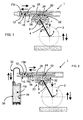
- FIG. 1 results in a suspension device 1 according to the invention for "single-wheel suspension", ie the load-bearing and resilient support of only schematically indicated wheel 2 in a motor vehicle.
- the wheel 2 is to rotatably mounted at one end of a Schwingentragarms 4 about a wheel axis 6, wherein the Schwingentragarm 4 is pivotable about a parallel to the wheel axis 6 swing axle 8 so that it oscillates by about vertical wheel suspension movements back and forth about the swing arm 8th is pivoted.
- the movements and flow directions during compression of the wheel 2 are each illustrated by fully drawn arrows and the rebound by dashed arrows.
- the suspension device 1 is in the simplest basic version according to Fig. 1 from a spring cylinder 10, which in turn consists of a pressure cylinder 12 and a piston 14 guided relatively movable therein. It should already be noted that both alternatives are possible with respect to this relative movement; so can - compare, inter alia Fig. 1 -
- the pressure cylinder 12 stationary held in the vehicle and the piston 14 to be movable, or - see Fig. 28 and 29 - With fixedly supported piston 14, the pressure cylinder 12 may be movable.
- the piston 14 is sealed by a peripheral seal 16 against the inner wall of the pressure cylinder 12, so that it forms a displaceable boundary wall of a cylinder pressure chamber 18.
- the pressure chamber 18 is filled with an elastically compressible spring medium FM, so that the piston 14 acts directly against the spring medium FM.
- the suspension device 1 has a drive device 20 in such a manner that the oscillating suspension pivoting movements of the oscillating support arm 4 carrying the wheel 2 are converted into the linear relative movements between the pressure cylinder 12 and the piston 14.
- the piston 14 acts in this case against the spring medium FM, that by the elastic compression of a respective wheel load bearing or this corresponding spring force F is generated.
- the drive device 20 is designed as a toothed gear 22.
- This gear transmission 22 consists of a rotatably mounted about the rocker axis 8 gear member 24 and a rack member 26, which in the first embodiments Fig. 1 is connected to the piston 14, while the pressure cylinder 12 is fixedly secured in the vehicle.
- the gear member 24 is connected or connectable to the swing arm 4, so that the gear member 24 is oscillated back and forth correspondingly by the suspension movements of the wheel 2 and the oscillating pivoting movements of the Schwingentragarms 4.
- the piston 14 is linearly reciprocated via the rack member 26 accordingly.
- Fig. 1 In the execution after Fig. 1 is exclusively the cylinder pressure chamber 18 in particular completely filled with the compressible spring medium FM.
- This spring medium FM is in this case a compressible fluid with a compressibility of at least 10%.
- silicone can be used, which may have a compressibility of about 18%.
- the printing cylinder 12 is tube-like extended on its side facing away from the pressure chamber 18 side. This area serves for the mechanical guidance of the rack element 26.
- the gear element 24 engages through an opening 28 into the area of the rack element 26.
- the entire arrangement of the spring cylinder 10 and gear transmission 22 summarized by a common support member 30 and is thereby fastened via the support member 30 on the vehicle.
- the carrier element 30 may advantageously also have the bearing means for the toothed gearing 22 or the gear element 24.
- the wheel 2 is thus suspended via the Schwingentragarm 4 on the vehicle-mounted Erten spring device 1.
- Fig. 2 This is initially essentially the same as the implementation Fig. 1 , The only difference here is that the pressure chamber 18 is connected via a line 32 with an additional space 34, which is also preferably completely filled with the compressible spring medium FM. As shown, the additional space 34 may be formed by a separate storage container 36. In a compression of the wheel 2 not only the spring medium FM is compressed in the pressure chamber 18, but also the additional spring medium in the additional space 34. The same applies to a relaxation of the spring medium in the event of rebound of the wheel 2. In this embodiment, therefore, an increase of the available volume of the spring medium FM achieved (larger compression volume).
- the spring characteristic can be changed and / or it can be the maximum stroke of the spring travel (also stroke of the rack member 26) are increased.
- the spring medium used has a compressibility of 18%, this means that, for example, 100 cm 3 can be compressed to 82 cm 3 , with a certain increase in force being required for this compression. Consequently, the ratio of the compression can be determined via the volume, or it can be increased or decreased with the same compression ratio of the stroke (travel).
- Fig. 1 and 2 The advantage of the designs Fig. 1 and 2 is that only one medium FM is used. Furthermore, compared to a gas, a simple seal is possible. In addition to a gas is a significant advantage of the compressible liquid that a change in volume in the case of Temperature change is several times lower than for gas. This advantageously eliminates an additional expense for a compensation of temperature-induced changes in volume.
- the explanations after Fig. 1 and 2 allow only a relatively small change in the compression ratios within the existing suspension device 1. In addition, the total working volume must be relatively large, because the compressibility is relatively low.
- the piston 14 acts indirectly via a hydraulic medium and thus practically not or only slightly insensitive medium HM against a compressible pneumatic spring medium FM.
- the pressure chamber 18 of the spring cylinder 10 is connected via a line 38 with a hydropneumatic spring accumulator 40.
- This spring accumulator preferably consists of a storage cylinder 42 and a floating, freely movable guided separating piston 44, which divides a storage space 46 of a spring chamber 48.
- the pressure chamber 18 of the spring cylinder 10 and the storage space 46 of the spring accumulator 40 are filled with the hydraulic medium HM.
- a suitable gas is arranged under compression bias.
- Gas as spring medium FM has the advantage that it can be compressed very strongly. Since a strong compression is to be achieved, it is a prerequisite that the gas is not flammable. This requirement is fulfilled by so-called noble gases, such as nitrogen, argon, helium, crypton or neon.
- noble gases such as nitrogen, argon, helium, crypton or neon.
- the advantage of the design according to Fig. 3 is that in this case a very simple adjustment of the compression force or spring characteristic can be realized. This can be done by adjusting the pressure of the gas volume when filling the spring chamber 48.
- Another advantage is that the compression volume can be substantially none other than the compressible fluid according to Fig. 1 and 2 , This allows a very small overall volume of the device can be achieved.
- a damping device 50 for damping the suspension movements mainly the Ausfederungsschien provided.
- a Damper valve 52 is arranged in the line connection 38 between the spring cylinder 10 and spring accumulator 40 . The damping takes place here by throttling the flowing hydraulic medium HM.
- Fig. 4 are for the finishes Fig. 1 to 3 the respective acting forces are drawn.
- a bearing load 58 acts due to the weight 56 and the respective inclination of the swing arm 4 to the vertical.
- a pivot bearing 60 of the gear element 24 connected to the swing arm 4 is loaded with the force 64 by the weight force 62.
- a toothed force 66 acts in the direction of the rotary bearing 60 in the region of the meshing toothings of the toothed wheel gear 22.
- tooth forces act on the pivot bearing 60 as a result of the unilateral tooth engagement of the toothed wheel element element 24.
- These tooth forces can be relatively high since the entire force acts on the (only one) toothed rack element 26.
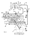
- the gear mechanism 22 acts on the same gear member 24 against an additional, equally acting spring cylinder 10. It is preferably a point or axisymmetric arrangement to the rocker axis 8, wherein two of the two spring cylinders 10 associated rack members 26 are on diametrically opposite sides of the gear member 24 with this engaged. This results in an H-shaped arrangement.
- the two pressure chambers 18 of the spring cylinder 10 are connected via lines 38 to the same hydropneumatic spring accumulator 40. In each line 38 may - as shown - a damping valve 52 may be connected.
- the main advantage of this design Fig. 5 is that the forces in the region of the respective teeth are halved and in addition the bearing of the gear member 24 is relieved. Overall, this results in a more favorable (symmetrical) distribution of forces.
- each pressure chamber 18 of the two same effect Spring cylinder 10 is connected to one of two separate spring memories 40.
- the force or the course of force can be variably adjusted by means of a different compression setting of the spring medium within the two spring chambers 48 via the stroke or path of the rack elements 26.
- This makes it possible to realize a certain force curve, since the forces of the two rack elements add to the gear element. It is consequently possible to realize different force profiles over the stroke or path of the rack elements and thus over the angle of rotation of the gear element 24 than is possible with the compression of only one spring medium or gas volume.
- This advantageous embodiment can be used to achieve, for example towards the end of the spring travel a high increase in force. As a result, the wheel 2 is strongly braked during the deflection and the mechanical stop is not so hard. Also in this embodiment according to Fig. 6 can be arranged in at least one or both lines 38, a damping valve 52.
- the hydraulic medium HM is damped in the suspension circuit. By damping or throttling the hydraulic medium HM is heated in each case. This heat is also transferred to the spring medium FM, resulting in a temperature-induced pressure change.
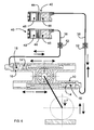
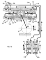
- the damping device 50 has a separate, independent of the spring cylinder 10 and the spring medium FM circuit of a hydraulic damping medium DM. As a result, a thermal decoupling of the damping circuit is achieved by the spring circuit prematurely.
- the damping device 50 at least one damper cylinder 70 with a relatively movable in a cylinder 72 damper piston 74 and at least one hydraulically connected to the damper cylinder 70 damping valve 52.
- two counter-rotating damper cylinder 70 are provided.
- the two damper pistons 74 of the two damper cylinders 70 are connected to the ends of a common rack member 26 and are driven by the same gear member 24 as well as the rack member 26 of the spring cylinder 10.
- the two rack members 26 are - similar to Fig. 5 and 6 - On diametrically opposite sides of the gear member 24th arranged.
- Each damper piston 74 acts against the arranged in the cylinder chamber 76 damping medium DM. Due to the described arrangement, the two cylinder chambers 76 in the exact same extent in opposite directions volume variable. As a result, the damping medium DM is in each case displaced from one cylinder space 76 during the suspension movements and received by the other cylinder space 76. In this flow, the damping medium DM is damped in the damping valve 52.
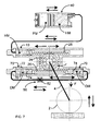
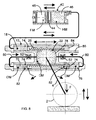
- Fig. 8 is a variant too Fig. 7 illustrated in which a gear housing 22 receiving housing space 78 is included in the damping circuit.
- the housing space 78 is filled with the damping medium DM and connected via a respective line 80 with the two cylinder chambers 76.
- a damping valve 52 is arranged in each case.
- each damper piston 74 preferably has a flow passage with a check valve (suction valve) 82.
- the damping medium does not flow directly from one cylinder chamber 76 into the other cylinder chamber 76, but the respectively displaced damping medium DM is displaced via the respective damping valve 52 into the housing space 78, and the respectively increasing cylinder chamber 76 fills via the suction valve 82
- the main advantage of this design is that the gear transmission 22 and the bearing points of the gear element 24 are arranged in an oil bath and thus a permanent lubrication is ensured.
- rack member 26 is also connected on its opposite side with another piston 84, said piston 84 is guided sealed in a cylinder portion 86.
- the rack member 26 opposite side of the cylinder portion 86 is formed open or connected to the atmosphere.
- the embodiment according to Fig. 9 corresponds with respect to the damping device 50 of the embodiment according to Fig. 8 ,
- the region of the cylinder portion is formed as an additional spring cylinder 10.
- the thus existing two spring cylinders 10 act in opposite directions by the piston 14 on the same rack member 26 are connected.
- the pressure chambers 18, which are thus variable in volume, are each connected to one of two separate spring accumulators 40.
- the pressures of the two spring accumulator 4 against each other so that a differential force arises on the rack member 26, and only this differential force acts on the gear member 24 as the actual spring force F of the suspension device. 1
- a first dashed curve 88 illustrates the force curve of the in Fig. 9 shown on the right spring memory 40, the pressure or force increases in the compression direction.
- a second dashed curve 90 illustrates the course of the pressure or the force of in Fig. 9
- a fully drawn characteristic curve 92 illustrates the overall characteristic resulting from the addition of the two partial characteristic curves. The mode of action is as follows:
- the (upper) rack member 26 shifts, increases in one memory, the pressure and in the other, the pressure drops, as from the one pressure chamber 18, the hydraulic medium is pushed into a spring store and in the opposite pressure chamber 18, the hydraulic medium flows from the other spring accumulator.
- Prerequisite for the desired mode of action is that the pressure in one spring storage in the static position is different from the pressure of the other spring accumulator. This too is in Fig. 26 illustrated. Furthermore, the graph shows that one force decreases as the other force increases and vice versa.
- the advantage of this embodiment is that the temperature influence of the volume change of the spring medium is reduced.
- both volumes expand in the spring chambers 48. Since the expansion of the one volume leads to hydraulic medium being pushed into the associated pressure chamber 18 and as a result the rack element 26 shifts in the direction of the other pressure chamber 18, hydraulic medium is pushed from the latter into the associated spring accumulator 40. But as the spring medium also expands in this spring store, not only will the pressure increased by the flowing in hydraulic medium, but also by the temperature-induced expansion in this spring accumulator. This double pressure increase means that only a relatively smaller displacement of the rack member 26 is effected by the spring accumulator with higher pressure against the spring accumulator with the lower pressure.
- the rack member thus makes much less displacement than without the preferred provided counter pressure control.
- the positional displacement of the wheel 2 on the Schwingentragarm 4 is low, so that advantageously no additional measure for level control is required, including, for example, hydraulic fluid could be discharged into the system or drained from it.
- Fig. 10 is a constructive variant for execution Fig. 9 shown.
- This design basically has the same effect as the execution after Fig. 9 as far as the compensation of the temperature influence is concerned.
- the first pressure chamber 18, which decreases in a deflection of the wheel 2 has a larger volume and a larger cross section than the second, oppositely acting pressure chamber 18 a.
- this is achieved in that the pressure cylinder 12a of this counteracting spring cylinder 10a has a reduced internal cross section.
- the piston 14 is connected to a corresponding smaller auxiliary piston 14a.
- the larger pressure chamber 18 is connected to a larger spring accumulator 40a, while the smaller pressure chamber 18a is connected to a smaller spring accumulator 40b.
- the counter-control to compensate for the temperature expansion of the spring medium in the spring accumulator 40a is thus achieved by a relatively smaller displaced volume.
- the spring memory 40b with small spring medium volume, in which the small hydraulic volume is pressed, is dimensioned so that a small amount of hydraulic pressure leads to a high pressure increase. This high pressure increase leads to a large force change, which counteracts the expansion of the spring medium in the larger spring accumulator 40a.
- Fig. 11 shows a further variant to the statements Fig. 9 and 10 ,
- the temperature compensation is integrated directly into the spring accumulator 40.
- the separating piston 44 of the spring accumulator 40 a Piston rod 94, which extends axially through the storage space 46 and sealed by an intermediate wall 96 passes into an additional pressure chamber 98 protrudes.
- This pressure chamber 98 can be acted upon with a particular pneumatic back pressure.
- the separating piston 44 is displaced in the direction of the storage space 46.
- the piston rod 94 is further displaced into the pressure chamber 98.
- Fig. 12 illustrated embodiment corresponds with respect to the suspension circuit of the embodiment according to Fig. 5 with two same-acting and cooperating with a common spring accumulator 40 spring cylinders 10, which, however, also in the sense of Fig. 6 can be connected to two separate spring memories 40.
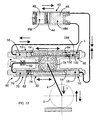
- the damping device 50 is also independent of the suspension circuit, but in this case only one damper cylinder 70 is provided, the cylinder chamber 76 is connected via the damping valve 52 to the housing chamber 78.
- the damper piston 74 is also equipped here with a suction valve 82. It is preferably provided that in the region of the cylinder portion 86, a compensation chamber 100 is formed for the damping medium DM.
- This compensation chamber 100 is separated from the housing chamber 78 via the piston 84, but the piston 84 has a flow opening 102. Since in the suspension movements the volume of the housing chamber 78 included in the damping circuit always remains constant, the compensation chamber 100 serves as a tank for receiving the volume of the damping medium DM respectively displaced from the cylinder chamber 76 of the damper cylinder 70.
- the compensation chamber 100 also contains an air cushion L which is at least as big that it can compensate for the maximum volume difference of the damping device 50.
- Fig. 13 corresponds to that according to Fig. 12
- the flow path in the damping circuit is designed so that upon displacement of the damping medium DM from the cylinder chamber 76 flows through this only via the damping valve 52, but the required inflow in the reverse case of an increase of the cylinder chamber 76 only via the suction valve 82 in the damper piston 74.
- This solution has the advantage that the damping valve 52 can be made simpler and thus cheaper.
- a hydraulic end position damping is provided, for which purpose at least in each spring cylinder 10, a path-dependent hydraulic throttle device 104 is integrated.
- the damper cylinders 70 can be equipped with corresponding throttle devices 104. These throttling devices 104 cause the movement to be decelerated in both directions toward the end of the suspension stroke so that hard mechanical shocks at the end of the suspension movements are avoided.
- Fig. 15 this embodiment is exemplary in the embodiment of the suspension device 1 according to Fig. 11 illustrated.
- each damper cylinder 70 is equipped with a throttle device 104.
- the effect of the end position damping or the throttling devices 104 can be adapted to the respective conditions of rebound and rebound. This is expedient since usually the compression speed is higher than the rebound speed of the wheel 2.
- Fig. 16 exemplified a constructive solution for the throttle device 104 is illustrated.
- This path-dependent hydraulic throttle device 104 may optionally be installed in the respective pistons 14 and 74 (as shown) or in a closure cap 106 of the respective cylinder.
- Throttle device 104 has a plunger 110 that can be displaced axially against a spring 108 in such a way that, starting at a specific position, it is at the end of the suspension stroke slides like a slider in a guide 112. In this case, the plunger on an axial flow channel 114, into which open a plurality of radial, distributed over the length arranged transverse openings 116.
- the transverse openings 116 are successively closed successively until they reach the end stop position.
- the flow resistance is increased successively, because the hydraulic medium can flow out only via the flow channel 114 of the plunger 110.
- the respective movement is gently braked; a hard end stop is advantageously avoided.
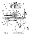
- Fig. 17 is a simplified embodiment of the suspension device 1 illustrated in which the gear transmission 22 only a rack member 26 in terms of Fig. 1 to 4 having.
- the rack member 26 is connected on one side with the piston 14 of the spring cylinder 10 and on the other side with the damper piston 74 of the damper cylinder 70.
- the suspension circuit thus corresponds to the execution Fig. 3
- the damping circuit of the damping device 50 has a connected to the cylinder chamber 76 via the damping valve 52 tank 118, in which the damping medium displaces DM during rebound of the wheel 2 and from which the damping medium DM is sucked during compression.
- This version after Fig. 17 is suitable for suspension tasks in which the spring forces are relatively low.
- the gear housing 22 receiving housing space 78 is used as the tank 118 of the hydraulic circuit of the damping device 50.
- the gear member 24 is disposed vertically above the rack member 26, and within the housing space 78 (tank 118) above the damping medium DM an air cushion L is included.
- the air volume L must be such that the volume displaced from the cylinder space 76 plus any thermal expansion can be absorbed by the tank 118. Since the gear member 24 is disposed above the rack member 26, the oil level is higher than the cylinder chamber 76 of the damper cylinder 70. By this arrangement, the damping medium DM flows into an enlargement of the cylinder chamber 76 better into this than when the tank 118 below the cylinder chamber 76th is arranged, since in this case the medium would have to be sucked.
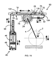
- Fig. 19 Such an embodiment is in Fig. 19 illustrated. Accordingly, the gear member 24 is disposed vertically below the rack member 26, whereby the tank 118 is located substantially below the cylinder chamber 76 of the damper cylinder 70 and thus the damping medium DM must be sucked at an enlargement of the cylinder chamber 76.
- the tank 118 is connected to a pressure accumulator, not shown, which sets the tank space under a pressure of for example about 5 bar.
- Fig. 19 provided arrangement of the gear member 24 on the side on which the wheel 2 is suspended via the Schwingentragarm 4, opposite Fig. 18 the advantage of a more favorable distribution of force; this will be on again Fig. 4 pointed.
- the embodiments with two rack elements 26 are actually of less importance for relieving the bearing point of the gear element 24; the advantage of the double rack assembly is mainly in the distribution of hydraulic forces and the resulting tooth load of the gears of the gear transmission 22.
- the embodiments with only one rack member have the advantage of a very compact design, since the space in a vehicle is often so limited in that a somewhat stronger gear element with a stronger rack element can be accommodated better in space than a double version in a possibly flatter design.
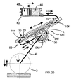
- the embodiment illustrated in FIG Fig. 18 be arranged in such a diagonally oriented mounting position that the damper cylinder 70 is at least always arranged vertically below the dividing line 120 between the damping medium DM and air cushion L with its cylinder chamber 76. This always ensures that the damping medium DM flows into the cylinder chamber 76 when it becomes larger. For reasons of cost, this installation position is preferable to additional measures, as long as the installation situation in the respective vehicle permits it.
- Fig. 19 corresponding execution according to Fig. 21 is illustrated as an advantageous embodiment that by creating an additional space 122, the volume of the tank 118 can be increased, which is favorable for the heat balance of the damping medium DM, because the greater the Volume of the damping medium DM is, the lower it heats up.
- the additional space 122 is preferably vertically above the gear transmission 22.
- the additional space 122 may be formed by an approximately bell-shaped housing extension.
- a further advantage of this embodiment is that the entire gear transmission 22, including the toothed rack element 26 arranged vertically above the gear element 24, runs completely in the oil bath and thus the wear can be reduced.
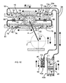
- Fig. 22 Based on Fig. 22 is exemplary of the execution Fig. 21 an advantageous development in the field of damping device 50 explained. It is an additional device 124 such that slight suspension movements, and advantageously even in the direction of rebound, almost without damping of the damping medium DM are possible, while a damping automatically starts only after a certain travel.
- the cylinder chamber 76 of the damper cylinder 70 is connected directly to a storage space 126 in which a disk-shaped stop element 128 is freely movable between the damping medium DM and an air cushion L. This stop element 128 floats practically on the oil level of the damping medium DM.
- damping medium DM now flows into the storage space 126 during a suspension movement, the stop element 128 is raised against the air cushion L by the rising oil level. However, this movement is limited in a position corresponding to a certain travel by an inner stop step 130 within the storage space 126.
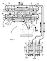
- a further variant of the damping device 50 is illustrated, which makes it possible, in the compression direction - in addition to the line damping between the spring cylinder 10 and spring accumulator 40 - to achieve a targeted damping.
- the damper cylinder 70a is designed as a double-acting cylinder unit in that the damping piston 74a inside the cylinder 72a separates an annular space 76a from a piston chamber 76b.
- the damper piston 74a is connected via a piston rod 134 with a guide piston 136, which in turn is connected to the rack member 26 and therefore shifts in accordance with the suspension movements and the damper piston 74a moves accordingly via the piston rod 134.
- the guide piston 136 is sealed as a conclusion of the housing space 78 and the tank 118 formed therein against the housing via a first seal 138.
- the piston rod 134 is sealed in the housing via a second seal 140 and the damper piston 74a has a third seal 142 (piston ring).
- the second seal 140 separates the annular space 76a surrounding the piston rod 134 from an air-filled chamber 144 formed between the first seal 138 and the second seal 140.
- the piston chamber 76b is preferably connected to the auxiliary device 124 described above or to the storage chamber 126. For damping, the piston chamber 76b is further connected to the tank 118 via a first damping valve 52a, and the annular space 76a is also connected to the tank 118 via a second damping valve 52b.
- first seal 138 ensures that the tank formed in the housing chamber 78 is not increased or decreased by the movements of the rack member 26. Instead, only a volume change occurs in the region of the chamber 144, which is irrelevant because of the air contained therein.
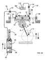
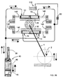
- Fig. 28 and 29 two exemplary embodiments are illustrated, wherein a "kinematic reversal" is provided in the area of the cylinders and pistons.
- a "kinematic reversal" is provided in the area of the cylinders and pistons.
- the or each piston is supported in a stationary manner on carrier elements 148 via one or more piston rods 146, while the or each cylinder is driven via the respective rack element 26.
- Fig. 28 it is an embodiment with only one, in particular above the gear member 24 arranged cylinder-piston unit, while the execution according to Fig. 29 represents a double solution.
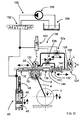
- Fig. 30 is exemplary by way of execution
- Fig. 24 illustrates that the suspension device 14 may additionally be equipped with a leveling device 150.
- This leveling device 150 is connected to the suspension circuit to supply or discharge hydraulic fluid for changing the static vehicle level.
- the leveling device 150 consists of a switching valve 152, a tank 154 and a pump 156.
- the switching valve 152 is designed as a 3/3-way valve and closed in the illustrated position.
- the pump 156 can be connected to the suspension circuit to supply hydraulic fluid and thereby raise the level.
- the suspension circuit is connected to the tank 154 in order to drain hydraulic fluid for lowering the level. This change in level is due to the fact that the entire weight of the vehicle does not change.
- a means 158 for changing the damping characteristic In this case, the or each damping valve 52 or 52a, b adjustable to change the damping effect and to a control pressure acted upon.
- This control pressure may advantageously be the respective pressure dependent on the load within the hydraulic spring circuit.
- This pressure can briefly via a switching valve 160 to the respective damping valve to be switched. This advantageously achieves that an adaptation of the damping to the respective load state of the vehicle is possible.
Landscapes
- Engineering & Computer Science (AREA)
- Mechanical Engineering (AREA)
- General Engineering & Computer Science (AREA)
- Vehicle Body Suspensions (AREA)
Applications Claiming Priority (2)
| Application Number | Priority Date | Filing Date | Title |
|---|---|---|---|
| DE20209120U DE20209120U1 (de) | 2002-06-12 | 2002-06-12 | Federungseinrichtung für Kraftfahrzeuge |
| EP03735399A EP1511642B1 (fr) | 2002-06-12 | 2003-05-16 | Dispositif de suspension pour vehicules automobiles |
Related Parent Applications (1)
| Application Number | Title | Priority Date | Filing Date |
|---|---|---|---|
| EP03735399.2 Division | 2003-05-16 |
Publications (1)
| Publication Number | Publication Date |
|---|---|
| EP2241460A1 true EP2241460A1 (fr) | 2010-10-20 |
Family
ID=29265510
Family Applications (2)
| Application Number | Title | Priority Date | Filing Date |
|---|---|---|---|
| EP10171674A Withdrawn EP2241460A1 (fr) | 2002-06-12 | 2003-05-16 | Dispositif de suspension pour véhicule automobile |
| EP03735399A Expired - Lifetime EP1511642B1 (fr) | 2002-06-12 | 2003-05-16 | Dispositif de suspension pour vehicules automobiles |
Family Applications After (1)
| Application Number | Title | Priority Date | Filing Date |
|---|---|---|---|
| EP03735399A Expired - Lifetime EP1511642B1 (fr) | 2002-06-12 | 2003-05-16 | Dispositif de suspension pour vehicules automobiles |
Country Status (6)
| Country | Link |
|---|---|
| US (2) | US7392998B2 (fr) |
| EP (2) | EP2241460A1 (fr) |
| AT (1) | ATE533649T1 (fr) |
| AU (1) | AU2003236662A1 (fr) |
| DE (1) | DE20209120U1 (fr) |
| WO (1) | WO2003106202A1 (fr) |
Families Citing this family (38)
| Publication number | Priority date | Publication date | Assignee | Title |
|---|---|---|---|---|
| EP2196337B1 (fr) | 2008-12-12 | 2012-05-02 | HEMSCHEIDT FAHRWERKTECHNIK GmbH & Co. KG | Dispositif d'amortissement pour véhicules |
| US8151953B2 (en) | 2004-04-08 | 2012-04-10 | Samsung Electronics Co., Ltd. | Suspension and damping device for motor vehicles |
| DE202004005623U1 (de) | 2004-04-08 | 2005-08-11 | Hemscheidt Fahrwerktechnik Gmbh & Co. Kg | Federungs- und Dämpfungseinrichtung für Kraftfahrzeuge |
| DE102005026047A1 (de) * | 2005-06-03 | 2006-12-14 | Benteler Automobiltechnik Gmbh | Radführung |
| DE202005011439U1 (de) | 2005-07-18 | 2006-11-23 | Hemscheidt Fahrwerktechnik Gmbh & Co. Kg | Federungseinrichtung für Kraftfahrzeuge |
| JP2008094226A (ja) * | 2006-10-11 | 2008-04-24 | Kayaba Ind Co Ltd | サスペンション装置 |
| US8376100B2 (en) * | 2008-04-17 | 2013-02-19 | Levant Power Corporation | Regenerative shock absorber |
| US8839920B2 (en) | 2008-04-17 | 2014-09-23 | Levant Power Corporation | Hydraulic energy transfer |
| US8392030B2 (en) * | 2008-04-17 | 2013-03-05 | Levant Power Corporation | System and method for control for regenerative energy generators |
| US7954834B2 (en) * | 2008-07-03 | 2011-06-07 | Douglas Pokupec | Linkage for a vehicle suspension |
| US8235405B1 (en) * | 2008-07-03 | 2012-08-07 | Douglas Pokupec | Linkage for a vehicle suspension |
| EP2527171A1 (fr) | 2008-11-18 | 2012-11-28 | Hemscheidt Fahrwerktechnik GmbH & Co. KG | Système d'amortissement pour véhicules |
| DE202008018221U1 (de) | 2008-12-12 | 2012-02-27 | Hemscheidt Fahrwerktechnik Gmbh & Co. Kg | Dämpfungseinrichtung für Fahrzeuge |
| CZ303603B6 (cs) | 2009-07-09 | 2013-01-02 | Technická univerzita v Liberci | Záves kola vozidla, zvlášte vozidla pro jízdu v nerovném terénu |
| CZ303586B6 (cs) * | 2009-07-09 | 2012-12-27 | Technická univerzita v Liberci | Záves pojezdového kola nebo tuhé nápravy vozidla, zvlášte vozidla pro jízdu v nerovném terénu |
| EP3643918B1 (fr) | 2010-06-16 | 2023-08-02 | ClearMotion, Inc. | Amortisseur de génération d'énergie intégré |
| KR101204907B1 (ko) * | 2011-06-07 | 2012-11-26 | 삼성테크윈 주식회사 | 암휠형 차량 |
| CN102320227B (zh) * | 2011-06-09 | 2013-12-18 | 三一汽车起重机械有限公司 | 一种车辆及其平衡悬架 |
| JP6408486B2 (ja) | 2012-12-14 | 2018-10-17 | オハイオ ユニバーシティ | リセット式半受動剛性ダンパ及びその使用方法 |
| US9809078B2 (en) | 2013-03-15 | 2017-11-07 | ClearMotion, Inc. | Multi-path fluid diverter valve |
| WO2014145018A2 (fr) | 2013-03-15 | 2014-09-18 | Levant Power Corporation | Améliorations apportées à la suspension active d'un véhicule |
| US9702349B2 (en) | 2013-03-15 | 2017-07-11 | ClearMotion, Inc. | Active vehicle suspension system |
| US9174508B2 (en) | 2013-03-15 | 2015-11-03 | Levant Power Corporation | Active vehicle suspension |
| EP3825156A1 (fr) | 2013-04-23 | 2021-05-26 | ClearMotion, Inc. | Suspension active dotée d'un actionneur structural |
| US9702424B2 (en) | 2014-10-06 | 2017-07-11 | ClearMotion, Inc. | Hydraulic damper, hydraulic bump-stop and diverter valve |
| CN104879430B (zh) * | 2015-05-25 | 2016-09-07 | 常州舒安车辆有限公司 | 具有智能自动调整预压力功能的减震器 |
| CN105235465B (zh) * | 2015-10-13 | 2017-11-14 | 海汇新能源车辆有限公司 | 一种基于机械传动的汽车减震器发电机构 |
| CN106671718B (zh) * | 2016-08-10 | 2020-07-24 | 山东交通学院 | 一种馈能悬架装置 |
| JP6896257B2 (ja) * | 2017-11-10 | 2021-06-30 | 株式会社Tok | ヒンジアームダンパ機構 |
| US11365782B2 (en) | 2017-12-07 | 2022-06-21 | Marelli Suspension Systems Italy S.P.A. | Rotary damper, particularly for vehicle suspension |
| CN108045481B (zh) * | 2017-12-14 | 2020-04-03 | 定远县中林机械技术有限公司 | 一种电动平衡车自动平衡装置 |
| IT201800020989A1 (it) * | 2018-12-24 | 2020-06-24 | Sistemi Sospensioni Spa | Compensazione dell'effetto termico in un sistema di sospensione di un veicolo. |
| CN110329031B (zh) * | 2019-06-06 | 2022-03-04 | 中国北方车辆研究所 | 一种可实现大角度旋转调节的摇臂悬架 |
| CN110478605B (zh) * | 2019-09-20 | 2021-08-13 | 中南大学湘雅医院 | 一种心血管扩张装置 |
| US20230055142A1 (en) * | 2021-08-18 | 2023-02-23 | DRiV Automotive Inc. | Damper assembly and syringe pump |
| CN115626005B (zh) * | 2022-10-20 | 2025-10-17 | 吉林大学 | 一种可重构行走机构 |
| KR20240166241A (ko) * | 2023-05-17 | 2024-11-26 | 현대자동차주식회사 | 차량용 현가장치 |
| CN116972112B (zh) * | 2023-07-10 | 2026-01-02 | 江苏大学 | 一种可变惯容的叶轮丝杆式惯性与阻尼设备 |
Citations (4)
| Publication number | Priority date | Publication date | Assignee | Title |
|---|---|---|---|---|
| US1290293A (en) * | 1918-04-15 | 1919-01-07 | American Motor Spring Patents Company | Shock-absorber and suspension for vehicles. |
| US3085796A (en) * | 1959-05-13 | 1963-04-16 | Volvo Ab | Hydropneumatic suspension and damping device for vehicles |
| EP0980772A2 (fr) * | 1998-08-20 | 2000-02-23 | Technology Investments Limited | Système de suspension de véhicule |
| US6142495A (en) * | 1997-11-04 | 2000-11-07 | Hyundai Motor Company | Stabilizer for vehicle |
Family Cites Families (10)
| Publication number | Priority date | Publication date | Assignee | Title |
|---|---|---|---|---|
| BE375994A (fr) | ||||
| US1116293A (en) * | 1914-02-02 | 1914-11-03 | Joseph G Waters | Apparatus for transforming energy. |
| US1397879A (en) * | 1921-04-06 | 1921-11-22 | William F Pillmore | Attachment for automobiles |
| US1470931A (en) | 1921-05-04 | 1923-10-16 | Alfred J Perkins | Shock absorber |
| US1500277A (en) | 1921-07-23 | 1924-07-08 | Selker Harry | Shock absorber |
| US1493884A (en) | 1922-02-24 | 1924-05-13 | Kreider Enos Henry | Shock absorber |
| US2706009A (en) * | 1951-06-08 | 1955-04-12 | Arthur G Schramm | Elevatable bed automotive vehicles |
| US3689103A (en) * | 1970-11-27 | 1972-09-05 | Pneumo Dynamics Corp | Variable height vehicle suspension |
| US3921746A (en) * | 1972-12-28 | 1975-11-25 | Alexander J Lewus | Auxiliary power system for automotive vehicle |
| KR100293672B1 (ko) * | 1997-11-21 | 2001-07-12 | 이계안 | 자동차의현가장치 |
-
2002
- 2002-06-12 DE DE20209120U patent/DE20209120U1/de not_active Expired - Lifetime
-
2003
- 2003-05-16 AT AT03735399T patent/ATE533649T1/de active
- 2003-05-16 US US10/517,807 patent/US7392998B2/en not_active Expired - Fee Related
- 2003-05-16 EP EP10171674A patent/EP2241460A1/fr not_active Withdrawn
- 2003-05-16 AU AU2003236662A patent/AU2003236662A1/en not_active Abandoned
- 2003-05-16 WO PCT/EP2003/005142 patent/WO2003106202A1/fr not_active Ceased
- 2003-05-16 EP EP03735399A patent/EP1511642B1/fr not_active Expired - Lifetime
-
2008
- 2008-05-21 US US12/124,513 patent/US7578512B2/en not_active Expired - Fee Related
Patent Citations (4)
| Publication number | Priority date | Publication date | Assignee | Title |
|---|---|---|---|---|
| US1290293A (en) * | 1918-04-15 | 1919-01-07 | American Motor Spring Patents Company | Shock-absorber and suspension for vehicles. |
| US3085796A (en) * | 1959-05-13 | 1963-04-16 | Volvo Ab | Hydropneumatic suspension and damping device for vehicles |
| US6142495A (en) * | 1997-11-04 | 2000-11-07 | Hyundai Motor Company | Stabilizer for vehicle |
| EP0980772A2 (fr) * | 1998-08-20 | 2000-02-23 | Technology Investments Limited | Système de suspension de véhicule |
Also Published As
| Publication number | Publication date |
|---|---|
| US7578512B2 (en) | 2009-08-25 |
| EP1511642A1 (fr) | 2005-03-09 |
| AU2003236662A1 (en) | 2003-12-31 |
| US7392998B2 (en) | 2008-07-01 |
| US20080277894A1 (en) | 2008-11-13 |
| WO2003106202A1 (fr) | 2003-12-24 |
| EP1511642B1 (fr) | 2011-11-16 |
| ATE533649T1 (de) | 2011-12-15 |
| US20060208446A1 (en) | 2006-09-21 |
| DE20209120U1 (de) | 2003-10-16 |
Similar Documents
| Publication | Publication Date | Title |
|---|---|---|
| EP1511642B1 (fr) | Dispositif de suspension pour vehicules automobiles | |
| DE60109417T2 (de) | Aufhängungssystem für ein fahrzeug | |
| DE69803839T2 (de) | Doppeltwirkender dämpfer mit volumenausgleich für den hub der stange | |
| EP2097279B1 (fr) | Regulation de niveau a autopompage | |
| EP3746676B1 (fr) | Amortisseur de vibrations pour un véhicule | |
| DE112013004595B4 (de) | Aufhängungsvorrichtung | |
| DE102008006476B4 (de) | Gasdruckstoßdämpfer | |
| DE1253072B (de) | Druckmittelanlage fuer die mit Druckmittel arbeitende Federung von Kraftfahrzeugen | |
| DE102007028634A1 (de) | Kolben-Zylinder-Aggregat | |
| DE4031626A1 (de) | Hydraulischer schwingungsdaempfer | |
| EP0854815B1 (fr) | Colonne de direction pour automobile | |
| DE10328841A1 (de) | Modul aus Luftfeder und Stossdämpfer mit innerer lastabhängiger Dämpfungseinstellung | |
| DE10306564B3 (de) | Dämpfer | |
| WO2022018157A1 (fr) | Système d'entraînement destiné à un volet d'un véhicule automobile | |
| DE3817031A1 (de) | Knickgesteuertes fahrzeug mit hydraulischer lenkung | |
| WO2019020625A1 (fr) | Système d'amortisseur et de suspension d'une roue de véhicule | |
| DE102006008608B4 (de) | Radaufhängung | |
| EP2404078B1 (fr) | Système d'amortissement pour amortissement de butée | |
| EP1584502B1 (fr) | Dispositif de suspension et d'amortissement pour véhicules motorisés | |
| DE60022350T2 (de) | Selbstregulierender kraftfahrzeugdämpfer mit selbstkorrigierender dämpfungscharakteristik | |
| EP0427001B1 (fr) | Chariot élévateur avec un mât de levage disposé mobilement | |
| WO1988007454A1 (fr) | Systeme d'amortisseur mecanique/hydraulique a compensation de niveau pour vehicules a moteur | |
| DE19923880C2 (de) | Verstellbares Ventil, insbesondere für einen Feststeller zwischen zwei relativ zueinander beweglichen Objekten | |
| EP2669515B1 (fr) | Pompe ainsi que son utilisation | |
| DE10237703A1 (de) | Blockierbares hydropneumatisches Federsystem mit automatischer Anpassung an unterschiedliche Fahrergewichte und Fahrbahntypologie |
Legal Events
| Date | Code | Title | Description |
|---|---|---|---|
| PUAI | Public reference made under article 153(3) epc to a published international application that has entered the european phase |
Free format text: ORIGINAL CODE: 0009012 |
|
| AC | Divisional application: reference to earlier application |
Ref document number: 1511642 Country of ref document: EP Kind code of ref document: P |
|
| AK | Designated contracting states |
Kind code of ref document: A1 Designated state(s): AT BE BG CH CY CZ DE DK EE ES FI FR GB GR HU IE IT LI LU MC NL PT RO SE SI SK TR |
|
| 17P | Request for examination filed |
Effective date: 20110119 |
|
| GRAP | Despatch of communication of intention to grant a patent |
Free format text: ORIGINAL CODE: EPIDOSNIGR1 |
|
| RIC1 | Information provided on ipc code assigned before grant |
Ipc: B60G 7/02 20060101ALI20130121BHEP Ipc: B60G 17/00 20060101AFI20130121BHEP Ipc: F16F 9/06 20060101ALI20130121BHEP Ipc: B60G 11/30 20060101ALI20130121BHEP Ipc: B60G 3/14 20060101ALI20130121BHEP |
|
| GRAP | Despatch of communication of intention to grant a patent |
Free format text: ORIGINAL CODE: EPIDOSNIGR1 |
|
| INTG | Intention to grant announced |
Effective date: 20130614 |
|
| STAA | Information on the status of an ep patent application or granted ep patent |
Free format text: STATUS: THE APPLICATION IS DEEMED TO BE WITHDRAWN |
|
| 18D | Application deemed to be withdrawn |
Effective date: 20131025 |