EP2244923B1 - Sensoranordnung - Google Patents
Sensoranordnung Download PDFInfo
- Publication number
- EP2244923B1 EP2244923B1 EP09700577.1A EP09700577A EP2244923B1 EP 2244923 B1 EP2244923 B1 EP 2244923B1 EP 09700577 A EP09700577 A EP 09700577A EP 2244923 B1 EP2244923 B1 EP 2244923B1
- Authority
- EP
- European Patent Office
- Prior art keywords
- sensor
- spacer
- under inspection
- rail
- inspection
- Prior art date
- Legal status (The legal status is an assumption and is not a legal conclusion. Google has not performed a legal analysis and makes no representation as to the accuracy of the status listed.)
- Active
Links
Images


Classifications
-
- B—PERFORMING OPERATIONS; TRANSPORTING
- B61—RAILWAYS
- B61K—AUXILIARY EQUIPMENT SPECIALLY ADAPTED FOR RAILWAYS, NOT OTHERWISE PROVIDED FOR
- B61K9/00—Railway vehicle profile gauges; Detecting or indicating overheating of components; Apparatus on locomotives or cars to indicate bad track sections; General design of track recording vehicles
- B61K9/08—Measuring installations for surveying permanent way
- B61K9/10—Measuring installations for surveying permanent way for detecting cracks in rails or welds thereof
-
- G—PHYSICS
- G01—MEASURING; TESTING
- G01N—INVESTIGATING OR ANALYSING MATERIALS BY DETERMINING THEIR CHEMICAL OR PHYSICAL PROPERTIES
- G01N27/00—Investigating or analysing materials by the use of electric, electrochemical, or magnetic means
- G01N27/72—Investigating or analysing materials by the use of electric, electrochemical, or magnetic means by investigating magnetic variables
- G01N27/82—Investigating or analysing materials by the use of electric, electrochemical, or magnetic means by investigating magnetic variables for investigating the presence of flaws
- G01N27/90—Investigating or analysing materials by the use of electric, electrochemical, or magnetic means by investigating magnetic variables for investigating the presence of flaws using eddy currents
- G01N27/9006—Details, e.g. in the structure or functioning of sensors
-
- G—PHYSICS
- G01—MEASURING; TESTING
- G01N—INVESTIGATING OR ANALYSING MATERIALS BY DETERMINING THEIR CHEMICAL OR PHYSICAL PROPERTIES
- G01N27/00—Investigating or analysing materials by the use of electric, electrochemical, or magnetic means
- G01N27/72—Investigating or analysing materials by the use of electric, electrochemical, or magnetic means by investigating magnetic variables
- G01N27/82—Investigating or analysing materials by the use of electric, electrochemical, or magnetic means by investigating magnetic variables for investigating the presence of flaws
- G01N27/90—Investigating or analysing materials by the use of electric, electrochemical, or magnetic means by investigating magnetic variables for investigating the presence of flaws using eddy currents
- G01N27/9013—Arrangements for scanning
- G01N27/902—Arrangements for scanning by moving the sensors
Definitions
- the present invention is directed to a means of enabling inspection of engineering components, such as rails used in the railway industry, using various sensors that make use of electromagnetic effects.
- Engineering components which are electrical conductors can be inspected using electromagnetic techniques. These include but are not limited to eddy current inspection, magnetic flux leakage, residual magnetism, alternating current flow measurement (acfm), and magnetic induction.
- All of these techniques rely on either an electromagnetic or magnetic field to be created in the vicinity of the surface of the component.
- the sensor measures either the absolute properties of the field, or far more commonly, variations of those properties as a function of the spatial relationship between sensor and surface position.
- the sensor will be scanned across the surface of the component either by moving the sensor with respect to the component or vice versa. As this relative movement occurs the interaction between the sensor and the field is monitored. Variations in the material of the component close to its surface will then be revealed as local disturbances of the field.
- Figure 1 shows a system, indicated generally by the reference numeral 1, in which the principles described above are applied.
- the system 1 comprises a component under inspection 2, a sensor 4, and a non-magnetic spacer 6.
- the spacer 6 and the sensor 4 move relative to the component 2.
- the spacer is sized to provide the appropriate spacing between the sensor 4 and the component 2.
- the separation is typically required to be of the order of about 1 or 2 millimetres for the sensor to maintain the appropriate sensitivity.
- Figure 2 shows a system 10 that is a variant of the system 1 described above.
- the system 10 comprises a component under inspection 12 and a sensor 14 similar to the component 2 and sensor 4 described above.
- the system 10 also comprises a mechanical arrangement 16 adapted to separate the component 12 and the sensor 14. In use, the mechanical arrangement 16 (and therefore also the sensor 14) moves relative to the component 12.
- the separation might typically be required to be of the order of about 1 or 2 millimetres for the sensor to maintain the required sensitivity.
- the response of the sensor is affected by two things: firstly the variation in the properties of the surface in the vicinity of the sensor, as described briefly above, but secondly the separation of the sensor and the surface under inspection. This latter parameter is often referred to as lift-off.
- the sensor can be maintained easily at a known distance from the surface, typically less than 1 mm.
- any variations in this separation will cause variations in the nature and magnitude of the response of the sensor so that any variations in the shape or morphology of the surface will cause significant variations in the output of the sensor. These variations commonly dominate those caused by the material variations.
- EP 1132 735 discloses an apparatus and method for detecting flaws in rail road rails.
- the apparatus comprises an ultrasonic flaw detector located within a wheel, the wheel arranged to be run along a rail being impacted.
- US 4,510,447 discloses an apparatus for electromagnetically detecting flaws in the wall of a pipe.
- An electromagnet with two poles in direct contact with the walls of a pipe being inspected is translated along the pipe and a sensor arrangement detects any variation in the eddy currents created.
- the present invention seeks to overcome or address one or more of the problems identified above.
- the present invention provides a rail inspection device with the features of claim 1.
- the object under test is a rail.
- the present invention also provides a method of rail inspection comprising the steps of claim 10.
- the method is a method of rail inspection.
- the object under inspection is a rail.
- the senor In use, the sensor is in contact with the inner surface of the spacer at the point where the outer surface of the spacer is in contact with the object under inspection.
- the present invention enables the separation of the sensor and the component under inspection to be maintained at a constant magnitude set by the thickness of the spacer.
- that dimension might be of the order of 1mmm to 2mm; in other embodiments, that dimension might be less than 1mm.
- the spacer Since the spacer is compliant, the spacer conforms to the shape of the object under inspection. Thus, the provision of a compliant spacer facilitates the constant separation of the sensor and the component being inspected even where the exact shape of the surface is unknown and where the relative velocity of movement of sensor and component is high. The nature of the device is such that the separation is maintained at a constant magnitude but without the limiting effect of wear and mechanical damage.
- the present invention addresses one of the main difficulties in successful inspection of engineering components which is the variation in separation of sensor and component.
- a further advantage of the new device is the mechanical protection afforded to the sensor as the sensor is moved across the component and encounters mechanical protuberances.
- the said spacer is circular and the sensor is positioned inside the circle.
- the spacer is a tyre.
- the space is rotatable.
- the spacer is arranged such that, in use, it is rolled along the device under test.
- the sensor is spring loaded or mounted on a spring loaded mechanism. In this manner, the spring is urged towards the inner surface of the spacer and hence towards the object under inspection. Thus, as the spacer flexes, the sensor remains in contact with the inner surface of the spacer.
- the spacer may be urged against the object under inspection.
- the sensor is an electromagnetic sensor. Further, the sensor may measure the variation in the electromagnetic properties of the surface of the object under inspection in the vicinity of the sensor.
- the electromagnetic properties being measured may be eddy currents.
- the spacer may be non-metallic.
- the object under inspection may be electrically conducting.
- the object under inspection is a railway rail.
- the sensor may, for example, be used to detect defects in such a railway rail.
- the spacer and the associated sensor may be moved relative to the object under inspection in order for measurements to be taken along said object.
- the spacer is rotated along the said object.
- the object under inspection may be moved relative to the sensor.
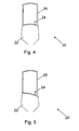
- FIGS 3 and 4 show a system, indicated generally by the reference numeral 20.
- the system 20 comprises a rail 22, one or more sensors 24, and a compliant tyre 26.
- the tyre is urged against the rail 22 and, since the tyre is compliant, the tyre conforms to the shape of the rail.
- the sensors 24 are mounted inside the tyre 26 such that the sensors are in contact with the inside surface of the tyre at the point where the outside of the tyre is in contact with the rail 22, as shown in Figure 3 .
- the sensors 24 are mounted on a sprung loaded device which presses the sensors against the inside of the tyre such that as the tyre flexes, the sensors remain in contact with the inside surface.
- Figure 5 shows a system, 20' that is identical to the system 20 described above, with the exception that the rail 22' has become worn through use.
- the compliance of the tyre 26' enables the tyre to take up the shape of the rail 22' in the transverse direction and because the sensor 24' is in contact with the inner surface of the tyre, the sensor remains a fixed distance from the surface, i.e. at the thickness of the tyre.
- the compliance of the tyre enables the shape to be followed and the sensors follow the tyre thus remaining at the same separation throughout the change of shape.
- the effects of lift-off are largely eliminated.
- Figure 6 shows the use of the present invention in a situation where a first rail 32a and second rail 32b meet. As shown in Figure 6 , the second rail is positioned slightly higher than the first rail; of course, such a scenario is common in practice.
- a sensor (not shown) is mounted inside a compliant tyre 36. Since the tyre 36 is compliant, it adjusts to the change in the shape of the components being measured as shown in Figure 6 .
Landscapes
- Chemical & Material Sciences (AREA)
- Mechanical Engineering (AREA)
- Engineering & Computer Science (AREA)
- Health & Medical Sciences (AREA)
- Physics & Mathematics (AREA)
- Life Sciences & Earth Sciences (AREA)
- Analytical Chemistry (AREA)
- Biochemistry (AREA)
- General Health & Medical Sciences (AREA)
- General Physics & Mathematics (AREA)
- Immunology (AREA)
- Pathology (AREA)
- Electrochemistry (AREA)
- Chemical Kinetics & Catalysis (AREA)
- Investigating Or Analyzing Materials By The Use Of Magnetic Means (AREA)
- Transmission And Conversion Of Sensor Element Output (AREA)
Claims (14)
- Gleisuntersuchungsgerät, aufweisend einen nachgiebigen Abstandshalter (26) und einen Sensor (24), wobei der Abstandshalter (26) eine innere Oberfläche und eine äußere Oberfläche aufweist, und wobei der Abstandshalter (26) kreisförmig ist, und der Sensor (24) innerhalb des Kreises angeordnet ist,
dadurch gekennzeichnet, dass
der Sensor (24) derart federgespannt ist, dass er gegen die innere Oberfläche des Abstandshalters (26) gedrängt wird, so dass in Verwendung die äußere Oberfläche des Abstandshalters in Kontakt mit der zu untersuchenden Schiene (22) ist,
und der Sensor (24) ein elektromagnetischer Sensor ist. - Gerät nach Anspruch 1, wobei der Abstandshalter (26) ein Reifen ist.
- Gerät nach einem der vorherigen Ansprüche, wobei der Abstandshalter (26) in Verwendung gegen den zu untersuchenden Gegenstand (22) gedrängt wird.
- Gerät nach einem der vorherigen Ansprüche, wobei der Abstandshalter (26) nichtmetallisch ist.
- Gerät nach einem der vorherigen Ansprüche, wobei der Sensor (26) die Veränderung der elektromagnetischen Eigenschaften der Oberfläche des zu untersuchenden Gegenstandes (22) in der Umgebung des Sensors misst.
- Gerät nach einem der vorherigen Ansprüche, wobei das zu untersuchende Gleis (22) elektrisch leitend ist.
- Gerät nach einem der vorherigen Ansprüche, wobei der Abstandshalter (26) rotierbar ist, so dass er in Verwendung so angeordnet ist, dass er entlang des zu untersuchenden Gleises (22) gerollt wird.
- Gerät nach einem der vorherigen Ansprüche, weiterhin aufweisend Mittel zum Antreiben des Abstandshalters (26) und des Sensors (24) im Verhältnis zu dem zu untersuchenden Gegenstand (22).
- Gerät, aufweisend ein Gerät nach den vorherigen Ansprüchen und weiterhin aufweisend den zu untersuchenden Gegenstand (22).
- Verfahren zur Untersuchung eines Gleises, aufweisend die folgenden Schritte:Bereitstellen eines nachgiebigen Abstandshalters (26),Befestigen eines Sensors (24) in eine federngespannte Anordnung, so dass sie gegen eine innere Oberfläche des Abstandshalters (26) gedrängt wird; undPositionieren des Abstandshalters (26) derart, dass eine äußere Oberfläche des Abstandshalters (26) in Kontakt mit einem zu untersuchenden Gleis (22) ist, wobei der Abstandshalter (26) kreisförmig ist, und der Sensor (24) innerhalb des Kreises positioniert wird, und der Sensor (26) ein elektromagnetischer Sensor ist.
- Verfahren nach Anspruch 10, weiterhin aufweisend den Schritt des Drängens des Abstandshalters (26) gegen das zu untersuchende Gleis.
- Verfahren nach Anspruch 10 oder Anspruch 11, weiterhin aufweisend den Schritt des Antreibens des Abstandshalters (26) und des Sensors (24) im Verhältnis zu dem zu untersuchenden Gleis (22).
- Verfahren nach Anspruch 12, wobei der Abstandshalter (26) entlang des zu untersuchenden Gleises (22) rotiert wird.
- Verfahren nach einem der Ansprüche 10-13, weiterhin aufweisend den Schritt des Verwendens des Sensors (24) zum Messen der Veränderung der elektromagnetischen Eigenschaften der Oberfläche des zu untersuchenden Gegenstands (22) in der Umgebung des Sensors.
Applications Claiming Priority (2)
| Application Number | Priority Date | Filing Date | Title |
|---|---|---|---|
| GBGB0800406.1A GB0800406D0 (en) | 2008-01-10 | 2008-01-10 | Sensor assembly |
| PCT/GB2009/000049 WO2009087385A2 (en) | 2008-01-10 | 2009-01-09 | Sensor assembly |
Publications (2)
| Publication Number | Publication Date |
|---|---|
| EP2244923A2 EP2244923A2 (de) | 2010-11-03 |
| EP2244923B1 true EP2244923B1 (de) | 2013-05-15 |
Family
ID=39144716
Family Applications (1)
| Application Number | Title | Priority Date | Filing Date |
|---|---|---|---|
| EP09700577.1A Active EP2244923B1 (de) | 2008-01-10 | 2009-01-09 | Sensoranordnung |
Country Status (8)
| Country | Link |
|---|---|
| US (1) | US9254851B2 (de) |
| EP (1) | EP2244923B1 (de) |
| CN (2) | CN104608798B (de) |
| CA (1) | CA2711552C (de) |
| ES (1) | ES2429420T3 (de) |
| GB (2) | GB0800406D0 (de) |
| PT (1) | PT2244923E (de) |
| WO (1) | WO2009087385A2 (de) |
Families Citing this family (16)
| Publication number | Priority date | Publication date | Assignee | Title |
|---|---|---|---|---|
| US10308265B2 (en) | 2006-03-20 | 2019-06-04 | Ge Global Sourcing Llc | Vehicle control system and method |
| US9733625B2 (en) | 2006-03-20 | 2017-08-15 | General Electric Company | Trip optimization system and method for a train |
| US9950722B2 (en) | 2003-01-06 | 2018-04-24 | General Electric Company | System and method for vehicle control |
| US9956974B2 (en) | 2004-07-23 | 2018-05-01 | General Electric Company | Vehicle consist configuration control |
| US9828010B2 (en) | 2006-03-20 | 2017-11-28 | General Electric Company | System, method and computer software code for determining a mission plan for a powered system using signal aspect information |
| US8914171B2 (en) | 2012-11-21 | 2014-12-16 | General Electric Company | Route examining system and method |
| CN102173296B (zh) * | 2011-01-26 | 2013-11-13 | 北京交通大学 | 一种同步驱动轮式电磁钢轨探伤装置 |
| US9981671B2 (en) | 2012-03-01 | 2018-05-29 | Nordco Inc. | Railway inspection system |
| GB2502989A (en) * | 2012-06-12 | 2013-12-18 | Sperry Rail International Ltd | Investigating the propagation of a crack in a rail |
| WO2014026091A2 (en) | 2012-08-10 | 2014-02-13 | General Electric Company | Route examining system and method |
| US9562878B2 (en) | 2012-09-13 | 2017-02-07 | Nordco Inc. | Rail condition monitoring system with carriage |
| US9255913B2 (en) | 2013-07-31 | 2016-02-09 | General Electric Company | System and method for acoustically identifying damaged sections of a route |
| GB2524610B (en) * | 2014-03-28 | 2016-09-21 | Technical Software Consultants Ltd | A.C. Field measurement system |
| US10006877B2 (en) | 2014-08-20 | 2018-06-26 | General Electric Company | Route examining system and method |
| GB2542800B (en) * | 2015-09-29 | 2020-02-19 | Sperry Rail International Ltd | Apparatus and method for detecting flaws in rails |
| EP4103781A1 (de) * | 2020-02-13 | 2022-12-21 | Hyperloop Technologies, Inc. | System und verfahren zum changieren einer nicht beweglichen schienenweiche mittels elektromagnetischer motoren |
Family Cites Families (26)
| Publication number | Priority date | Publication date | Assignee | Title |
|---|---|---|---|---|
| GB359432A (en) | 1929-07-23 | 1931-10-19 | Sozo Sakurai | Improvements in electromagnetic apparatus for detecting faults in rails |
| US2337148A (en) * | 1939-05-17 | 1943-12-21 | Walter C Barnes | Flaw detecting apparatus |
| US2356967A (en) * | 1940-02-24 | 1944-08-29 | Walter C Barnes | Flaw detecting apparatus |
| US2671197A (en) * | 1950-09-02 | 1954-03-02 | Walter C Barnes | Magnetizing means for rail flaw detector systems |
| FR1301911A (fr) * | 1961-07-08 | 1962-08-24 | Rochar Electronique | Dispositif palpeur destiné à l'examen des rails de chemins de fer à l'aide d'ultra-sons |
| JPS55119559A (en) * | 1979-03-10 | 1980-09-13 | Japan National Railway | Eddy current type high speed raillflow detector |
| US4510447A (en) * | 1981-10-26 | 1985-04-09 | Exxon Production Research Co. | Inspection apparatus for electromagnetically detecting flaws in the wall of a pipe |
| US4885710A (en) * | 1987-06-25 | 1989-12-05 | Delco Electronics Corporation | Method and apparatus for low speed estimation |
| US4819459A (en) | 1988-08-19 | 1989-04-11 | Keith John R | Front loading cleaning machine |
| CH679776A5 (de) * | 1989-11-07 | 1992-04-15 | Rieter Ag Maschf | |
| US8604932B2 (en) * | 1992-05-05 | 2013-12-10 | American Vehicular Sciences, LLC | Driver fatigue monitoring system and method |
| CH690851A5 (fr) * | 1996-11-25 | 2001-02-15 | Speno Internat S A | Dispositif de mesure des défauts internes d'un rail par ultrasons. |
| JPH11183441A (ja) | 1997-12-18 | 1999-07-09 | Tokyo Gas Co Ltd | 回転型渦流探傷装置 |
| ES2151832B1 (es) * | 1998-08-04 | 2001-07-16 | Talgo Patentes | Instalacion para la evaluacion automatica del estado de la banda de rodadura en ruedas de trenes en movimiento. |
| DE69839824D1 (de) * | 1998-10-23 | 2008-09-11 | Gang Li | Verfahren, transducerrad sowie system zur ultraschalldetektion von fehlern in eisenbahnschienen |
| CN1103449C (zh) * | 1998-10-23 | 2003-03-19 | 李钢 | 钢轨超声探轮和探伤装置 |
| US6768298B2 (en) * | 2001-07-17 | 2004-07-27 | Transportation Technology Center, Inc. | Transverse crack detection in rail head using low frequency eddy currents |
| CN2649444Y (zh) * | 2003-09-05 | 2004-10-20 | 罗望保 | 铁路轨道信息采集装置 |
| US7521917B2 (en) * | 2004-06-25 | 2009-04-21 | General Electric Company | Method and apparatus for testing material integrity |
| US7466126B2 (en) * | 2004-07-12 | 2008-12-16 | General Electric Company | Universal sensor probe with adjustable members configured to fit between a plurality of slot openings of varying widths |
| US7882842B2 (en) * | 2004-09-21 | 2011-02-08 | Pavad Medical, Inc. | Airway implant sensors and methods of making and using the same |
| US7305885B2 (en) * | 2004-09-30 | 2007-12-11 | General Electric Company | Method and apparatus for phased array based ultrasonic evaluation of rail |
| CN2825394Y (zh) * | 2005-08-02 | 2006-10-11 | 刘波 | 智能型轨道检查车 |
| US7312608B2 (en) | 2005-11-03 | 2007-12-25 | The Boeing Company | Systems and methods for inspecting electrical conductivity in composite materials |
| US7849748B2 (en) * | 2008-05-15 | 2010-12-14 | Sperry Rail, Inc. | Method of and an apparatus for in situ ultrasonic rail inspection of a railroad rail |
| US9008884B2 (en) * | 2010-12-15 | 2015-04-14 | Symbotic Llc | Bot position sensing |
-
2008
- 2008-01-10 GB GBGB0800406.1A patent/GB0800406D0/en active Pending
-
2009
- 2009-01-09 PT PT97005771T patent/PT2244923E/pt unknown
- 2009-01-09 CN CN201410809490.XA patent/CN104608798B/zh active Active
- 2009-01-09 WO PCT/GB2009/000049 patent/WO2009087385A2/en not_active Ceased
- 2009-01-09 US US12/812,326 patent/US9254851B2/en active Active
- 2009-01-09 GB GB1013314.8A patent/GB2469009B/en active Active
- 2009-01-09 CA CA2711552A patent/CA2711552C/en active Active
- 2009-01-09 ES ES09700577T patent/ES2429420T3/es active Active
- 2009-01-09 CN CN2009801019549A patent/CN101918260A/zh active Pending
- 2009-01-09 EP EP09700577.1A patent/EP2244923B1/de active Active
Also Published As
| Publication number | Publication date |
|---|---|
| GB2469009B (en) | 2012-07-25 |
| US20110043199A1 (en) | 2011-02-24 |
| CN104608798B (zh) | 2021-07-30 |
| ES2429420T3 (es) | 2013-11-14 |
| GB201013314D0 (en) | 2010-09-22 |
| WO2009087385A3 (en) | 2009-10-15 |
| WO2009087385A2 (en) | 2009-07-16 |
| EP2244923A2 (de) | 2010-11-03 |
| GB2469009A (en) | 2010-09-29 |
| CA2711552A1 (en) | 2009-07-16 |
| CN101918260A (zh) | 2010-12-15 |
| US9254851B2 (en) | 2016-02-09 |
| PT2244923E (pt) | 2013-07-18 |
| CN104608798A (zh) | 2015-05-13 |
| CA2711552C (en) | 2016-09-06 |
| GB0800406D0 (en) | 2008-02-20 |
Similar Documents
| Publication | Publication Date | Title |
|---|---|---|
| EP2244923B1 (de) | Sensoranordnung | |
| US7038445B2 (en) | Method, system and apparatus for ferromagnetic wall monitoring | |
| JP4829883B2 (ja) | 管を非破壊検査するための方法及び装置 | |
| CN102759567A (zh) | 直流磁化下钢管内外壁缺陷的涡流检测识别及评价方法 | |
| CN103842811B (zh) | 用于在金属制造过程中金属材料的裂纹检测的装置 | |
| KR101209451B1 (ko) | 비파괴 검사를 위한 자기탐상 장치 및 이에 의한 비파괴 검사방법 | |
| US7521917B2 (en) | Method and apparatus for testing material integrity | |
| RU2542624C1 (ru) | Способ вихретокового контроля медной катанки и устройство для его реализации | |
| EP3356812B1 (de) | Verfahren und vorrichtung zum nachweis von fehlstellen in schienen | |
| EP3344982B1 (de) | Verfahren und system zur erkennung einer materialdiskontinuität bei einem magnetisierbaren artikel | |
| KR20140117983A (ko) | 강판 결함 탐상 장치 | |
| JP3743191B2 (ja) | 渦流探傷法 | |
| KR100946285B1 (ko) | 와전류를 이용한 와이어 로프 검사 장치 | |
| JP2007292760A (ja) | 材料の損傷を検出する装置 | |
| Yu et al. | Investigation on conductivity invariance in eddy current NDT and its application on magnetic permeability measurement | |
| CN100478645C (zh) | “8”字形线圈测距传感器 | |
| Khazi et al. | Microfabricated Eddy-Current Sensors for Non-Destructive Testing of the Micro Grinding Burn | |
| JP5013363B2 (ja) | 非破壊検査装置 | |
| JP2010243175A (ja) | バルクハウゼンノイズ検査装置 | |
| KR101309885B1 (ko) | 페인트 코팅된 강관재의 누설자속법을 이용한 결함 탐상 장치 및 이의 동작 방법 | |
| JP2014106136A (ja) | 漏洩磁束式検査装置および検査方法 | |
| JPS60230052A (ja) | 探傷方法及び装置 | |
| US9310337B2 (en) | Non-destructive inspection device for pressure containers using leakage-flux measurement | |
| JP2012088218A (ja) | 異物検出装置 | |
| KR20110135748A (ko) | 철도차량 차축 손상 검출 장치 |
Legal Events
| Date | Code | Title | Description |
|---|---|---|---|
| PUAI | Public reference made under article 153(3) epc to a published international application that has entered the european phase |
Free format text: ORIGINAL CODE: 0009012 |
|
| 17P | Request for examination filed |
Effective date: 20100805 |
|
| AK | Designated contracting states |
Kind code of ref document: A2 Designated state(s): AT BE BG CH CY CZ DE DK EE ES FI FR GB GR HR HU IE IS IT LI LT LU LV MC MK MT NL NO PL PT RO SE SI SK TR |
|
| AX | Request for extension of the european patent |
Extension state: AL BA RS |
|
| 17Q | First examination report despatched |
Effective date: 20110127 |
|
| DAX | Request for extension of the european patent (deleted) | ||
| GRAP | Despatch of communication of intention to grant a patent |
Free format text: ORIGINAL CODE: EPIDOSNIGR1 |
|
| GRAS | Grant fee paid |
Free format text: ORIGINAL CODE: EPIDOSNIGR3 |
|
| GRAA | (expected) grant |
Free format text: ORIGINAL CODE: 0009210 |
|
| AK | Designated contracting states |
Kind code of ref document: B1 Designated state(s): AT BE BG CH CY CZ DE DK EE ES FI FR GB GR HR HU IE IS IT LI LT LU LV MC MK MT NL NO PL PT RO SE SI SK TR |
|
| REG | Reference to a national code |
Ref country code: CH Ref legal event code: EP Ref country code: GB Ref legal event code: FG4D |
|
| REG | Reference to a national code |
Ref country code: AT Ref legal event code: REF Ref document number: 611990 Country of ref document: AT Kind code of ref document: T Effective date: 20130615 |
|
| REG | Reference to a national code |
Ref country code: IE Ref legal event code: FG4D |
|
| REG | Reference to a national code |
Ref country code: DE Ref legal event code: R096 Ref document number: 602009015699 Country of ref document: DE Effective date: 20130711 |
|
| REG | Reference to a national code |
Ref country code: PT Ref legal event code: SC4A Free format text: AVAILABILITY OF NATIONAL TRANSLATION Effective date: 20130715 |
|
| REG | Reference to a national code |
Ref country code: SE Ref legal event code: TRGR |
|
| REG | Reference to a national code |
Ref country code: CH Ref legal event code: PK Free format text: BERICHTIGUNG INHABER Ref country code: CH Ref legal event code: NV Representative=s name: SCHMAUDER AND PARTNER AG PATENT- UND MARKENANW, CH |
|
| REG | Reference to a national code |
Ref country code: NO Ref legal event code: T2 Effective date: 20130515 |
|
| REG | Reference to a national code |
Ref country code: AT Ref legal event code: MK05 Ref document number: 611990 Country of ref document: AT Kind code of ref document: T Effective date: 20130515 |
|
| REG | Reference to a national code |
Ref country code: LT Ref legal event code: MG4D |
|
| REG | Reference to a national code |
Ref country code: NL Ref legal event code: VDEP Effective date: 20130515 |
|
| PG25 | Lapsed in a contracting state [announced via postgrant information from national office to epo] |
Ref country code: LT Free format text: LAPSE BECAUSE OF FAILURE TO SUBMIT A TRANSLATION OF THE DESCRIPTION OR TO PAY THE FEE WITHIN THE PRESCRIBED TIME-LIMIT Effective date: 20130515 Ref country code: AT Free format text: LAPSE BECAUSE OF FAILURE TO SUBMIT A TRANSLATION OF THE DESCRIPTION OR TO PAY THE FEE WITHIN THE PRESCRIBED TIME-LIMIT Effective date: 20130515 Ref country code: GR Free format text: LAPSE BECAUSE OF FAILURE TO SUBMIT A TRANSLATION OF THE DESCRIPTION OR TO PAY THE FEE WITHIN THE PRESCRIBED TIME-LIMIT Effective date: 20130816 Ref country code: IS Free format text: LAPSE BECAUSE OF FAILURE TO SUBMIT A TRANSLATION OF THE DESCRIPTION OR TO PAY THE FEE WITHIN THE PRESCRIBED TIME-LIMIT Effective date: 20130915 Ref country code: FI Free format text: LAPSE BECAUSE OF FAILURE TO SUBMIT A TRANSLATION OF THE DESCRIPTION OR TO PAY THE FEE WITHIN THE PRESCRIBED TIME-LIMIT Effective date: 20130515 Ref country code: SI Free format text: LAPSE BECAUSE OF FAILURE TO SUBMIT A TRANSLATION OF THE DESCRIPTION OR TO PAY THE FEE WITHIN THE PRESCRIBED TIME-LIMIT Effective date: 20130515 |
|
| REG | Reference to a national code |
Ref country code: ES Ref legal event code: FG2A Ref document number: 2429420 Country of ref document: ES Kind code of ref document: T3 Effective date: 20131114 |
|
| PG25 | Lapsed in a contracting state [announced via postgrant information from national office to epo] |
Ref country code: PL Free format text: LAPSE BECAUSE OF FAILURE TO SUBMIT A TRANSLATION OF THE DESCRIPTION OR TO PAY THE FEE WITHIN THE PRESCRIBED TIME-LIMIT Effective date: 20130515 Ref country code: HR Free format text: LAPSE BECAUSE OF FAILURE TO SUBMIT A TRANSLATION OF THE DESCRIPTION OR TO PAY THE FEE WITHIN THE PRESCRIBED TIME-LIMIT Effective date: 20130515 Ref country code: BG Free format text: LAPSE BECAUSE OF FAILURE TO SUBMIT A TRANSLATION OF THE DESCRIPTION OR TO PAY THE FEE WITHIN THE PRESCRIBED TIME-LIMIT Effective date: 20130815 |
|
| PG25 | Lapsed in a contracting state [announced via postgrant information from national office to epo] |
Ref country code: LV Free format text: LAPSE BECAUSE OF FAILURE TO SUBMIT A TRANSLATION OF THE DESCRIPTION OR TO PAY THE FEE WITHIN THE PRESCRIBED TIME-LIMIT Effective date: 20130515 |
|
| PG25 | Lapsed in a contracting state [announced via postgrant information from national office to epo] |
Ref country code: SK Free format text: LAPSE BECAUSE OF FAILURE TO SUBMIT A TRANSLATION OF THE DESCRIPTION OR TO PAY THE FEE WITHIN THE PRESCRIBED TIME-LIMIT Effective date: 20130515 Ref country code: BE Free format text: LAPSE BECAUSE OF FAILURE TO SUBMIT A TRANSLATION OF THE DESCRIPTION OR TO PAY THE FEE WITHIN THE PRESCRIBED TIME-LIMIT Effective date: 20130515 Ref country code: EE Free format text: LAPSE BECAUSE OF FAILURE TO SUBMIT A TRANSLATION OF THE DESCRIPTION OR TO PAY THE FEE WITHIN THE PRESCRIBED TIME-LIMIT Effective date: 20130515 Ref country code: DK Free format text: LAPSE BECAUSE OF FAILURE TO SUBMIT A TRANSLATION OF THE DESCRIPTION OR TO PAY THE FEE WITHIN THE PRESCRIBED TIME-LIMIT Effective date: 20130515 Ref country code: CZ Free format text: LAPSE BECAUSE OF FAILURE TO SUBMIT A TRANSLATION OF THE DESCRIPTION OR TO PAY THE FEE WITHIN THE PRESCRIBED TIME-LIMIT Effective date: 20130515 |
|
| PG25 | Lapsed in a contracting state [announced via postgrant information from national office to epo] |
Ref country code: IT Free format text: LAPSE BECAUSE OF FAILURE TO SUBMIT A TRANSLATION OF THE DESCRIPTION OR TO PAY THE FEE WITHIN THE PRESCRIBED TIME-LIMIT Effective date: 20130515 Ref country code: RO Free format text: LAPSE BECAUSE OF FAILURE TO SUBMIT A TRANSLATION OF THE DESCRIPTION OR TO PAY THE FEE WITHIN THE PRESCRIBED TIME-LIMIT Effective date: 20130515 Ref country code: NL Free format text: LAPSE BECAUSE OF FAILURE TO SUBMIT A TRANSLATION OF THE DESCRIPTION OR TO PAY THE FEE WITHIN THE PRESCRIBED TIME-LIMIT Effective date: 20130515 |
|
| PLBE | No opposition filed within time limit |
Free format text: ORIGINAL CODE: 0009261 |
|
| STAA | Information on the status of an ep patent application or granted ep patent |
Free format text: STATUS: NO OPPOSITION FILED WITHIN TIME LIMIT |
|
| 26N | No opposition filed |
Effective date: 20140218 |
|
| REG | Reference to a national code |
Ref country code: DE Ref legal event code: R097 Ref document number: 602009015699 Country of ref document: DE Effective date: 20140218 |
|
| PG25 | Lapsed in a contracting state [announced via postgrant information from national office to epo] |
Ref country code: LU Free format text: LAPSE BECAUSE OF FAILURE TO SUBMIT A TRANSLATION OF THE DESCRIPTION OR TO PAY THE FEE WITHIN THE PRESCRIBED TIME-LIMIT Effective date: 20140109 Ref country code: MC Free format text: LAPSE BECAUSE OF FAILURE TO SUBMIT A TRANSLATION OF THE DESCRIPTION OR TO PAY THE FEE WITHIN THE PRESCRIBED TIME-LIMIT Effective date: 20130515 |
|
| REG | Reference to a national code |
Ref country code: DE Ref legal event code: R082 Ref document number: 602009015699 Country of ref document: DE Representative=s name: PATENTANWAELTE WEICKMANN & WEICKMANN, DE Ref country code: DE Ref legal event code: R082 Ref document number: 602009015699 Country of ref document: DE Representative=s name: WEICKMANN & WEICKMANN PATENTANWAELTE - RECHTSA, DE Ref country code: DE Ref legal event code: R082 Ref document number: 602009015699 Country of ref document: DE Representative=s name: WEICKMANN & WEICKMANN PATENT- UND RECHTSANWAEL, DE |
|
| REG | Reference to a national code |
Ref country code: FR Ref legal event code: PLFP Year of fee payment: 8 |
|
| PG25 | Lapsed in a contracting state [announced via postgrant information from national office to epo] |
Ref country code: MT Free format text: LAPSE BECAUSE OF FAILURE TO SUBMIT A TRANSLATION OF THE DESCRIPTION OR TO PAY THE FEE WITHIN THE PRESCRIBED TIME-LIMIT Effective date: 20130515 |
|
| PGFP | Annual fee paid to national office [announced via postgrant information from national office to epo] |
Ref country code: TR Payment date: 20160104 Year of fee payment: 8 |
|
| PG25 | Lapsed in a contracting state [announced via postgrant information from national office to epo] |
Ref country code: CY Free format text: LAPSE BECAUSE OF FAILURE TO SUBMIT A TRANSLATION OF THE DESCRIPTION OR TO PAY THE FEE WITHIN THE PRESCRIBED TIME-LIMIT Effective date: 20130515 |
|
| PG25 | Lapsed in a contracting state [announced via postgrant information from national office to epo] |
Ref country code: HU Free format text: LAPSE BECAUSE OF FAILURE TO SUBMIT A TRANSLATION OF THE DESCRIPTION OR TO PAY THE FEE WITHIN THE PRESCRIBED TIME-LIMIT; INVALID AB INITIO Effective date: 20090109 |
|
| REG | Reference to a national code |
Ref country code: FR Ref legal event code: PLFP Year of fee payment: 9 |
|
| REG | Reference to a national code |
Ref country code: FR Ref legal event code: PLFP Year of fee payment: 10 |
|
| PG25 | Lapsed in a contracting state [announced via postgrant information from national office to epo] |
Ref country code: MK Free format text: LAPSE BECAUSE OF FAILURE TO SUBMIT A TRANSLATION OF THE DESCRIPTION OR TO PAY THE FEE WITHIN THE PRESCRIBED TIME-LIMIT Effective date: 20130515 |
|
| PG25 | Lapsed in a contracting state [announced via postgrant information from national office to epo] |
Ref country code: TR Free format text: LAPSE BECAUSE OF NON-PAYMENT OF DUE FEES Effective date: 20170109 |
|
| PGFP | Annual fee paid to national office [announced via postgrant information from national office to epo] |
Ref country code: PT Payment date: 20250102 Year of fee payment: 17 |
|
| PGFP | Annual fee paid to national office [announced via postgrant information from national office to epo] |
Ref country code: ES Payment date: 20250206 Year of fee payment: 17 |
|
| PGFP | Annual fee paid to national office [announced via postgrant information from national office to epo] |
Ref country code: GB Payment date: 20251120 Year of fee payment: 18 |
|
| PGFP | Annual fee paid to national office [announced via postgrant information from national office to epo] |
Ref country code: FR Payment date: 20251110 Year of fee payment: 18 |
|
| PGFP | Annual fee paid to national office [announced via postgrant information from national office to epo] |
Ref country code: SE Payment date: 20251112 Year of fee payment: 18 |
|
| PGFP | Annual fee paid to national office [announced via postgrant information from national office to epo] |
Ref country code: IE Payment date: 20251111 Year of fee payment: 18 |
|
| REG | Reference to a national code |
Ref country code: CH Ref legal event code: U11 Free format text: ST27 STATUS EVENT CODE: U-0-0-U10-U11 (AS PROVIDED BY THE NATIONAL OFFICE) Effective date: 20260201 |
|
| PGFP | Annual fee paid to national office [announced via postgrant information from national office to epo] |
Ref country code: NO Payment date: 20260109 Year of fee payment: 18 Ref country code: DE Payment date: 20251111 Year of fee payment: 18 |
|
| PGFP | Annual fee paid to national office [announced via postgrant information from national office to epo] |
Ref country code: CH Payment date: 20260201 Year of fee payment: 18 |