EP2247167A2 - Procédé de détermination d'un type de lampe à décharge et appareil électrique monté en amont destiné au fonctionnement d'au moins deux types différents de lampes à décharge - Google Patents
Procédé de détermination d'un type de lampe à décharge et appareil électrique monté en amont destiné au fonctionnement d'au moins deux types différents de lampes à décharge Download PDFInfo
- Publication number
- EP2247167A2 EP2247167A2 EP10160067A EP10160067A EP2247167A2 EP 2247167 A2 EP2247167 A2 EP 2247167A2 EP 10160067 A EP10160067 A EP 10160067A EP 10160067 A EP10160067 A EP 10160067A EP 2247167 A2 EP2247167 A2 EP 2247167A2
- Authority
- EP
- European Patent Office
- Prior art keywords
- lamp
- preheating
- mess
- gas discharge
- lamp type
- Prior art date
- Legal status (The legal status is an assumption and is not a legal conclusion. Google has not performed a legal analysis and makes no representation as to the accuracy of the status listed.)
- Withdrawn
Links
- 238000000034 method Methods 0.000 description 14
- 238000004804 winding Methods 0.000 description 14
- 238000010438 heat treatment Methods 0.000 description 8
- 238000001514 detection method Methods 0.000 description 7
- 239000003990 capacitor Substances 0.000 description 4
- 241001136792 Alle Species 0.000 description 3
- 238000013459 approach Methods 0.000 description 3
- 230000006870 function Effects 0.000 description 3
- 238000005259 measurement Methods 0.000 description 3
- 230000006399 behavior Effects 0.000 description 2
- 230000008878 coupling Effects 0.000 description 2
- 238000010168 coupling process Methods 0.000 description 2
- 238000005859 coupling reaction Methods 0.000 description 2
- 230000001419 dependent effect Effects 0.000 description 2
- 230000002035 prolonged effect Effects 0.000 description 2
- 230000008859 change Effects 0.000 description 1
- 230000007423 decrease Effects 0.000 description 1
- 238000010586 diagram Methods 0.000 description 1
- 238000004519 manufacturing process Methods 0.000 description 1
- 230000008569 process Effects 0.000 description 1
- 230000000630 rising effect Effects 0.000 description 1
Images


Classifications
-
- H—ELECTRICITY
- H05—ELECTRIC TECHNIQUES NOT OTHERWISE PROVIDED FOR
- H05B—ELECTRIC HEATING; ELECTRIC LIGHT SOURCES NOT OTHERWISE PROVIDED FOR; CIRCUIT ARRANGEMENTS FOR ELECTRIC LIGHT SOURCES, IN GENERAL
- H05B41/00—Circuit arrangements or apparatus for igniting or operating discharge lamps
- H05B41/14—Circuit arrangements
- H05B41/26—Circuit arrangements in which the lamp is fed by power derived from DC by means of a converter, e.g. by high-voltage DC
- H05B41/28—Circuit arrangements in which the lamp is fed by power derived from DC by means of a converter, e.g. by high-voltage DC using static converters
- H05B41/295—Circuit arrangements in which the lamp is fed by power derived from DC by means of a converter, e.g. by high-voltage DC using static converters with semiconductor devices and specially adapted for lamps with preheating electrodes, e.g. for fluorescent lamps
-
- H—ELECTRICITY
- H05—ELECTRIC TECHNIQUES NOT OTHERWISE PROVIDED FOR
- H05B—ELECTRIC HEATING; ELECTRIC LIGHT SOURCES NOT OTHERWISE PROVIDED FOR; CIRCUIT ARRANGEMENTS FOR ELECTRIC LIGHT SOURCES, IN GENERAL
- H05B41/00—Circuit arrangements or apparatus for igniting or operating discharge lamps
- H05B41/14—Circuit arrangements
- H05B41/36—Controlling
Definitions
- the present invention relates to a method for determining a type of gas discharge lamp by means of an electronic ballast for operating different types of gas discharge lamps, wherein the different types of gas discharge lamps differ in at least one operating parameter, the method comprising the steps of: preheating at least one coil of the Gas discharge lamp for a predetermined preheat time, measuring a physical quantity characteristic of the type of the gas discharge lamp at the end of the preheat time and providing the measured value of that magnitude, and determining the lamp type from the provided measurement value.
- the invention also relates to a corresponding electronic ballast for operating at least two different types of gas discharge lamps.
- Electronic ballasts are known, which are suitable for the operation of different types of gas discharge lamps, in particular for the operation of different types of low-pressure discharge lamps.
- Such devices are referred to as multi-lamp devices or as intelligent electronic ballasts.
- operating parameters are stored for the types of lamps that can be operated with this device.
- different types of lamps differ in the lamp current required for their operation.
- the device selects the operating parameters to be used depending on the type of the connected lamp. For this it must first recognize the lamp type.
- a part of the currently known devices detects the lamp type by evaluating the cold resistance of a filament of the lamp at each start.
- the heat resistance of a lamp filament can also be evaluated at the end of the preheating phase.
- it can lead to error detection. If the lamp type is changed, then the Vortexparametersatz still used by the previous lamp is used for the newly connected lamp, so that it is not preheated optimally. This can lead to the determined value for the heat resistance of the coil being within a range that can not be clearly assigned to a lamp type. This can lead to error detection.
- a lamp is operated with incorrect parameter values, it may not ignite properly or the lamp life will be shortened.
- the object of the present invention is therefore to develop an aforementioned method and an aforementioned electronic ballast in such a way error detection of the lamp type can be avoided.
- the present invention is based on the finding that this object can be achieved if the duration of preheating is prolonged.
- the preheating time is extended by a predetermined period of time and a renewed determination of the lamp type is carried out at the end of the extended preheating time. It has been found that then there is an unambiguous assignability of the determined value for the heat resistance of the lamp filament to a lamp type, if the preheating time is chosen to be sufficiently long.
- the manufacturers of electronic ballasts for gas discharge lamps strive to keep the preheating time as short as possible in order to avoid that between the switching on and the ignition of the lamp a noticeable pause for the user.
- a preheating time which is preferably less than or equal to one second for preheating the set lamp type, and extending the preheating time only in those cases where unambiguous identification is not possible ,
- the method further comprises the step of storing the determined lamp type.
- the method also particularly preferably comprises the steps to be carried out at the start of the method of reading the stored lamp type and determining the predetermined preheating time as a function of the read-out type of lamp based on a stored in the electronic ballast between types of gas discharge lamps to be operated with the electronic ballast and associated operating parameters ,
- a lamp type is stored at the factory, which is used to determine the operating parameters to be used for the first preheating. Storing the determined lamp type is only required if this differs from the already stored lamp type.
- the physical quantity characteristic of the type of gas discharge lamp is the value of a value related to the electrical resistance of the preheated coil.
- the duration of the extended preheating time is preferably selected such that the measured value provided is located in a nearly stationary area.
- the heat resistance of the coil increases with the preheat time and asymptotically approaches a limit.
- the curve behavior in the steeply increasing range depends on the age of the coil, while the influence of the age of the coil in the stationary region of the curve is negligible.
- the lamp type is determined on the basis of the provided measured value by comparing the provided measured value with a table of values, then checking whether the provided measured value falls within a range of the table of values unambiguously attributable to a lamp type, and finally at unique assignability of the provided measured value to a lamp type of this lamp type is selected as the determined lamp type.
- different value tables are used for different operating parameters used in the preheating of the at least one helix. This also helps to increase the reliability of the lamp detection.
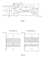
- Fig. 1 shows a schematic representation of an embodiment of an electronic ballast according to the invention.
- This comprises an input with a first input terminal E1 and a second input terminal E2, between which a mains voltage U N is applied.
- the input E1 and E2 are followed by a rectifier GL, which is designed to rectify the mains voltage U N.
- a power-factor correction circuit PFC is provided, which up-regulates the rectified voltage to a constant value and ensures a sinusoidal current drain from the grid.
- a half-bridge circuit is coupled to a first half-bridge switch S1 and a second half-bridge switch S2.
- a connected to the electronic ballast to be operated gas discharge lamp La load circuit is connected.
- This comprises a series resonant circuit which is composed of a choke coil L D and a resonant capacitor C R coupled between a first output terminal A1 and ground.
- a gas discharge lamp La to be operated with the electronic ballast is coupled.
- This in Fig. 1 embodiment shown represents an electronic ballast for operating a gas discharge lamp.
- the second output terminal A2 is also coupled via a coupling capacitor C K1 to ground.
- a second coupling capacitor C K2 Between the high potential terminal of the switch S1 and the second output terminal A2 may optionally be provided a second coupling capacitor C K2 , which is indicated in the figure by dashed lines.
- the present invention relates to a preheating device of the electronic ballast, which serves to preheat at least one and preferably both coils W1 and W2 of the gas discharge lamp La.
- the preheater has for this purpose a heating transformer with a primary winding TP and two secondary windings TS1 and TS2.
- the primary winding TR is connected via a switch S3 and a trapezoidal capacitor C T to the output of the half-bridge between the two switches S1 and S2.
- the first secondary winding TS1 is coupled to the first lamp filament W1, while the second secondary winding TS2 is coupled to the second lamp winding W2.
- the other end of the primary winding TP is for detecting a current flowing through the primary winding TP TP current I which is proportional to the current flowing through the secondary windings and through the lamp filaments streams connected to a measuring circuit 20th
- the measuring circuit 20 includes a shunt resistor and provides at its output derived from this voltage U mess .
- This voltage U mess is supplied to an input ME1 of a microcontroller 10.
- the microcontroller 10 also has outputs MA1, MA2 and MA3, via which it controls the switches S1 and S2 of the half-bridge and the switch S3, via which the heating device is coupled to the half-bridge.
- Fig. 1 also shows a memory 12 of the microcontroller 10 for storing data required for the operation of the gas discharge lamp La.
- the memory 12 is part of the microcontroller 10. Instead of a memory but could also be provided more memory, which could be arranged outside the microcontroller. If the intention is to operate several lamps of the same type simultaneously with the electronic ballast, the heating transformer comprises four instead of two secondary windings in the case of a device designed for the operation of two lamps. In the case of devices designed to operate more than two lamps, a heating transformer with one primary winding and one secondary winding for each coil to be heated is provided in each case for two lamps, the primary windings of the heating transformers being connected in parallel.
Landscapes
- Circuit Arrangements For Discharge Lamps (AREA)
Applications Claiming Priority (1)
| Application Number | Priority Date | Filing Date | Title |
|---|---|---|---|
| DE102009019625.0A DE102009019625B4 (de) | 2009-04-30 | 2009-04-30 | Verfahren zum Ermitteln eines Typs einer Gasentladungslampe und elektronisches Vorschaltgerät zum Betreiben von mindestens zwei unterschiedlichen Typen von Gasentladungslampen |
Publications (2)
| Publication Number | Publication Date |
|---|---|
| EP2247167A2 true EP2247167A2 (fr) | 2010-11-03 |
| EP2247167A3 EP2247167A3 (fr) | 2014-11-12 |
Family
ID=42338162
Family Applications (1)
| Application Number | Title | Priority Date | Filing Date |
|---|---|---|---|
| EP10160067.4A Withdrawn EP2247167A3 (fr) | 2009-04-30 | 2010-04-15 | Procédé de détermination d'un type de lampe à décharge et appareil électrique monté en amont destiné au fonctionnement d'au moins deux types différents de lampes à décharge |
Country Status (5)
| Country | Link |
|---|---|
| US (1) | US8754652B2 (fr) |
| EP (1) | EP2247167A3 (fr) |
| KR (1) | KR20100119524A (fr) |
| CN (1) | CN101877927B (fr) |
| DE (1) | DE102009019625B4 (fr) |
Families Citing this family (4)
| Publication number | Priority date | Publication date | Assignee | Title |
|---|---|---|---|---|
| CN102595747B (zh) * | 2012-02-05 | 2014-03-12 | 浙江大学 | 基于数字控制电子镇流器的荧光灯灯类型识别方法及数字通用电子镇流器 |
| JP6391997B2 (ja) * | 2014-06-06 | 2018-09-19 | 株式会社オーク製作所 | 発信機を備えた放電ランプおよびその光源装置 |
| KR101672538B1 (ko) * | 2015-04-22 | 2016-11-04 | 주식회사 미성포리테크 | 전·자기식 안정기 호환형 구동 회로 및 그 구동 회로를 포함한 led 형광등 |
| CN113219293B (zh) * | 2021-07-08 | 2022-03-18 | 深圳市爱图仕影像器材有限公司 | 光学附件检测电路及照明设备 |
Family Cites Families (48)
| Publication number | Priority date | Publication date | Assignee | Title |
|---|---|---|---|---|
| US5489823A (en) * | 1978-03-20 | 1996-02-06 | Nilssen; Ole K. | Electronic ballast for gas discharge lamp |
| US5841241A (en) * | 1982-01-25 | 1998-11-24 | Ole K. Nilssen | Electronic ballast for fluorescent lamps |
| US4503361A (en) * | 1982-02-02 | 1985-03-05 | Intent Patent A.G. | Electronic ballast system |
| US4730163A (en) * | 1985-03-13 | 1988-03-08 | Santos Luis S | Device for testing high-pressure lamps and components used therewith |
| DE3530638A1 (de) * | 1985-08-28 | 1987-03-05 | Philips Patentverwaltung | Schaltungsanordnung zum starten und betrieb von gasentladungslampen |
| DE3729383A1 (de) * | 1987-09-03 | 1989-03-16 | Philips Patentverwaltung | Schaltungsanordnung zum starten einer hochdruckgasentladungslampe |
| US4792727A (en) * | 1987-10-05 | 1988-12-20 | Gte Products Corporation | System and method for operating a discharge lamp to obtain positive volt-ampere characteristic |
| US4989127A (en) * | 1989-05-09 | 1991-01-29 | North American Philips Corporation | Driver for high voltage half-bridge circuits |
| JPH0766864B2 (ja) * | 1989-07-28 | 1995-07-19 | 東芝ライテック株式会社 | 放電灯点灯装置 |
| US5130611A (en) * | 1991-01-16 | 1992-07-14 | Intent Patents A.G. | Universal electronic ballast system |
| US5148087A (en) * | 1991-05-28 | 1992-09-15 | Motorola, Inc. | Circuit for driving a gas discharge lamp load |
| DE4329821A1 (de) * | 1993-09-03 | 1995-03-09 | Tridonic Bauelemente Ges Mbh | Elektronisches Vorschaltgerät zum Versorgen einer Last, beispielsweise einer Lampe |
| US5394062A (en) * | 1993-12-15 | 1995-02-28 | General Electric Company | Lamp ballast circuit with overload detection and ballast operability indication features |
| US5424611A (en) * | 1993-12-22 | 1995-06-13 | At&T Corp. | Method for pre-heating a gas-discharge lamp |
| US5656891A (en) * | 1994-10-13 | 1997-08-12 | Tridonic Bauelemente Gmbh | Gas discharge lamp ballast with heating control circuit and method of operating same |
| US5569984A (en) * | 1994-12-28 | 1996-10-29 | Philips Electronics North America Corporation | Method and controller for detecting arc instabilities in gas discharge lamps |
| DE19546588A1 (de) * | 1995-12-13 | 1997-06-19 | Patent Treuhand Ges Fuer Elektrische Gluehlampen Mbh | Verfahren und Schaltungsanordnung zum Betrieb einer Entladungslampe |
| US5804926A (en) * | 1996-04-08 | 1998-09-08 | Raytheon Company | Lighting circuit that includes a comparison of a "flattened" sinewave to a full wave rectified sinewave for control |
| US5801492A (en) * | 1996-05-30 | 1998-09-01 | Bobel; Andrzej | Electronic ballast for gas discharge lamp having primary and auxiliary resonant circuits |
| US5859504A (en) * | 1996-10-01 | 1999-01-12 | General Electric Company | Lamp ballast circuit with cathode preheat function |
| DE19708783C1 (de) * | 1997-03-04 | 1998-10-08 | Tridonic Bauelemente | Verfahren und Vorrichtung zum Regeln des Betriebsverhaltens von Gasentladungslampen |
| DK1042942T3 (da) * | 1997-07-24 | 2002-12-02 | Noontek Ltd | Elektronisk ballast til en gasudladningslampe |
| US5959408A (en) * | 1997-08-07 | 1999-09-28 | Magnetek, Inc. | Symmetry control circuit for pre-heating in electronic ballasts |
| US5952794A (en) * | 1997-10-02 | 1999-09-14 | Phillips Electronics North America Corportion | Method of sampling an electrical lamp parameter for detecting arc instabilities |
| SE520653C2 (sv) * | 1998-02-18 | 2003-08-05 | Pls Systems I Hestra Ab | Anordning för användning vid drift av en eller flera urladdningslampor |
| US6160361A (en) * | 1998-07-29 | 2000-12-12 | Philips Electronics North America Corporation | For improvements in a lamp type recognition scheme |
| US6169375B1 (en) * | 1998-10-16 | 2001-01-02 | Electro-Mag International, Inc. | Lamp adaptable ballast circuit |
| US6825620B2 (en) * | 1999-06-21 | 2004-11-30 | Access Business Group International Llc | Inductively coupled ballast circuit |
| US6359387B1 (en) * | 2000-08-31 | 2002-03-19 | Philips Electronics North America Corporation | Gas-discharge lamp type recognition based on built-in lamp electrical properties |
| DE10133515A1 (de) * | 2001-07-10 | 2003-01-30 | Patent Treuhand Ges Fuer Elektrische Gluehlampen Mbh | Schaltungsanordnung zum Betreiben einer Leuchtstofflampe |
| US6577078B2 (en) * | 2001-09-26 | 2003-06-10 | Koninklijke Philips Electronics N.V. | Electronic ballast with lamp run-up current regulation |
| US6731075B2 (en) * | 2001-11-02 | 2004-05-04 | Ampr Llc | Method and apparatus for lighting a discharge lamp |
| DE10200022A1 (de) * | 2002-01-02 | 2003-07-17 | Philips Intellectual Property | Schaltungsanordnung zum Betrieb einer oder mehrerer Lampen |
| EP1477045B1 (fr) * | 2002-02-19 | 2013-09-18 | Access Business Group International LLC | Ensemble demarreur pour lampe a decharge gazeuse |
| JP4000897B2 (ja) * | 2002-04-30 | 2007-10-31 | ウシオ電機株式会社 | 希ガス放電ランプの寿命予測方法、及び、希ガス放電ランプの寿命予測システム |
| DE10255737A1 (de) * | 2002-11-28 | 2004-06-09 | Patent-Treuhand-Gesellschaft für elektrische Glühlampen mbH | Verfahren zum Betrieb mindestens einer Niederdruckentladungslampe und Betriebsgerät für mindestens eine Niederdruckentladungslampe |
| DE10328718A1 (de) * | 2003-06-25 | 2005-01-13 | Patent-Treuhand-Gesellschaft für elektrische Glühlampen mbH | Verfahren zum Betrieb mindestens einer Niederdruckentladungslampe und Betriebsgerät für mindestens eine Niederdruckentladungslampe |
| DE10345610A1 (de) * | 2003-09-29 | 2005-05-12 | Patent Treuhand Ges Fuer Elektrische Gluehlampen Mbh | Verfahren zum Betreiben mindestens einer Niederdruckentladungslampe |
| US7109668B2 (en) * | 2003-10-30 | 2006-09-19 | I.E.P.C. Corp. | Electronic lighting ballast |
| WO2005060320A1 (fr) * | 2003-12-11 | 2005-06-30 | Koninklijke Philips Electronics, N.V. | Ballast electronique avec determination de type lampe |
| US6972570B2 (en) * | 2004-02-11 | 2005-12-06 | Schriefer Jay R | Quick-connect ballast testing and monitoring method and apparatus |
| US7145342B2 (en) * | 2004-07-07 | 2006-12-05 | Access Business Group International Llc | System and method for automated filament testing of gas discharge lamps |
| US7199528B2 (en) * | 2005-04-21 | 2007-04-03 | Energy Conservation Technologies, Inc. | Control circuit for maintaining constant power in power factor corrected electronic ballasts and power supplies |
| US7183714B1 (en) * | 2005-06-30 | 2007-02-27 | Osram Sylvania, Inc. | Ballast with relamping circuitry |
| DE102006045907A1 (de) * | 2006-09-28 | 2008-04-03 | Infineon Technologies Austria Ag | Verfahren und Vorrichtung zur Überwachung des Betriebs einer Gasentladungslampe |
| US7560867B2 (en) | 2006-10-17 | 2009-07-14 | Access Business Group International, Llc | Starter for a gas discharge light source |
| DE102007047142A1 (de) * | 2007-10-02 | 2009-04-09 | Tridonicatco Gmbh & Co. Kg | Verfahren zum Erkennen des Typs einer mit einem elektronischen Vorschaltgerät zu betreibenden Gasentladungslampe sowie elektronisches Vorschaltgerät |
| TWI382788B (zh) * | 2008-09-08 | 2013-01-11 | Ind Tech Res Inst | 高強度氣體放電燈之安定器驅動控制方法及其系統 |
-
2009
- 2009-04-30 DE DE102009019625.0A patent/DE102009019625B4/de not_active Expired - Fee Related
-
2010
- 2010-04-15 EP EP10160067.4A patent/EP2247167A3/fr not_active Withdrawn
- 2010-04-29 US US12/769,664 patent/US8754652B2/en not_active Expired - Fee Related
- 2010-04-30 CN CN201010169785.7A patent/CN101877927B/zh not_active Expired - Fee Related
- 2010-04-30 KR KR1020100040825A patent/KR20100119524A/ko not_active Withdrawn
Non-Patent Citations (1)
| Title |
|---|
| None |
Also Published As
| Publication number | Publication date |
|---|---|
| KR20100119524A (ko) | 2010-11-09 |
| CN101877927B (zh) | 2014-11-26 |
| DE102009019625B4 (de) | 2014-05-15 |
| EP2247167A3 (fr) | 2014-11-12 |
| CN101877927A (zh) | 2010-11-03 |
| US20100277178A1 (en) | 2010-11-04 |
| DE102009019625A1 (de) | 2010-11-25 |
| US8754652B2 (en) | 2014-06-17 |
Similar Documents
| Publication | Publication Date | Title |
|---|---|---|
| EP1103165B1 (fr) | Ballast electronique destine a au moins une lampe a decharge basse tension | |
| EP1519638B1 (fr) | Méthode pour commander une lampe à décharge basse pression | |
| EP0876742B1 (fr) | Procede et circuit de commande electronique pour la regulation des caracteristiques de fonctionnement de lampes a decharge | |
| DE102009019625B4 (de) | Verfahren zum Ermitteln eines Typs einer Gasentladungslampe und elektronisches Vorschaltgerät zum Betreiben von mindestens zwei unterschiedlichen Typen von Gasentladungslampen | |
| DE102008027029A1 (de) | Lampentyperkennung durch Leistungsfaktorkorrekturschaltung | |
| DE19708791A1 (de) | Steuerschaltung und elektronisches Vorschaltgerät mit einer derartigen Steuerschaltung | |
| EP1920642B1 (fr) | Ballast pour une lampe a decharge a prechauffage adaptatif | |
| EP2248395B1 (fr) | Identification du type d'une lampe à décharge destinée à fonctionner avec un ballast électronique | |
| DE3338464C2 (de) | Schaltungsanordnung zum Betrieb mindestens einer Leuchtstofflampe mit einstellbarer Helligkeit an einem selbstschwingenden Wechselrichter | |
| DE102007047142A1 (de) | Verfahren zum Erkennen des Typs einer mit einem elektronischen Vorschaltgerät zu betreibenden Gasentladungslampe sowie elektronisches Vorschaltgerät | |
| EP2248397B1 (fr) | Système d'éclairage et procédé destiné à contrôler si au moins deux lampes à décharge gazeuse destinées à fonctionner avec un ballast électronique sont du même type | |
| EP1492393A1 (fr) | Circuit et méthode pour alimenter une lampe à décharge muni d'une détection de fin de durée de vie | |
| EP1276355B1 (fr) | Circuit ballast pour determiner la puissance de préchauffage | |
| EP2198672B1 (fr) | Procédé pour déterminer des paramètres de fonctionnement d'une lampe à décharge de gaz fonctionnant avec un ballast électronique, et ballast correspondant | |
| EP1045619A1 (fr) | Procédé de calibration des paramètres d'opération d'un ballast pour lampe | |
| EP2274960B1 (fr) | Procédé et agencement de circuits pour faire fonctionner au moins une lampe à décharge | |
| EP2132965B1 (fr) | Circuit pour le chauffage d'un filament | |
| DE19613257A1 (de) | Verfahren und elektronische Steuerschaltung zum Regeln des Betriebsverhaltens von Gasentladungslampen | |
| EP1920643B1 (fr) | Ballast pour une lampe a decharge a prechauffage adaptatif | |
| AT518402B1 (de) | Schaltungsanordnung zum Betreiben einer Entladungslampe | |
| EP2468078B1 (fr) | Ballast électronique et procédé pour faire fonctionner au moins une lampe à décharge | |
| DE102008012454A1 (de) | Verfahren zum Bestimmen von Betriebsparametern einer mit einem elektronischen Vorschaltgerät zu betreibenden Gasentladungslampe sowie ein entsprechendes Vorschaltgerät | |
| DE10129453A1 (de) | Elektronisches Vorschaltgerät | |
| DE102010029475A1 (de) | Verfahren und Betriebsvorrichtung zum Betreiben von Entladungslampen unterschiedlichen Lampentyps |
Legal Events
| Date | Code | Title | Description |
|---|---|---|---|
| PUAI | Public reference made under article 153(3) epc to a published international application that has entered the european phase |
Free format text: ORIGINAL CODE: 0009012 |
|
| AK | Designated contracting states |
Kind code of ref document: A2 Designated state(s): AT BE BG CH CY CZ DE DK EE ES FI FR GB GR HR HU IE IS IT LI LT LU LV MC MK MT NL NO PL PT RO SE SI SK SM TR |
|
| AX | Request for extension of the european patent |
Extension state: AL BA ME RS |
|
| RAP1 | Party data changed (applicant data changed or rights of an application transferred) |
Owner name: OSRAM AG |
|
| RAP1 | Party data changed (applicant data changed or rights of an application transferred) |
Owner name: OSRAM GMBH |
|
| RAP1 | Party data changed (applicant data changed or rights of an application transferred) |
Owner name: OSRAM GMBH |
|
| PUAL | Search report despatched |
Free format text: ORIGINAL CODE: 0009013 |
|
| AK | Designated contracting states |
Kind code of ref document: A3 Designated state(s): AT BE BG CH CY CZ DE DK EE ES FI FR GB GR HR HU IE IS IT LI LT LU LV MC MK MT NL NO PL PT RO SE SI SK SM TR |
|
| AX | Request for extension of the european patent |
Extension state: AL BA ME RS |
|
| RIC1 | Information provided on ipc code assigned before grant |
Ipc: H05B 41/36 20060101AFI20141006BHEP Ipc: H05B 41/295 20060101ALI20141006BHEP |
|
| STAA | Information on the status of an ep patent application or granted ep patent |
Free format text: STATUS: THE APPLICATION IS DEEMED TO BE WITHDRAWN |
|
| 18D | Application deemed to be withdrawn |
Effective date: 20150513 |