EP2260959A2 - Dispositif de réglage pour un outil de finissage - Google Patents
Dispositif de réglage pour un outil de finissage Download PDFInfo
- Publication number
- EP2260959A2 EP2260959A2 EP10182981A EP10182981A EP2260959A2 EP 2260959 A2 EP2260959 A2 EP 2260959A2 EP 10182981 A EP10182981 A EP 10182981A EP 10182981 A EP10182981 A EP 10182981A EP 2260959 A2 EP2260959 A2 EP 2260959A2
- Authority
- EP
- European Patent Office
- Prior art keywords
- adjusting device
- pressure
- pressure chamber
- cutting edge
- tool
- Prior art date
- Legal status (The legal status is an assumption and is not a legal conclusion. Google has not performed a legal analysis and makes no representation as to the accuracy of the status listed.)
- Granted
Links
Images







Classifications
-
- B—PERFORMING OPERATIONS; TRANSPORTING
- B23—MACHINE TOOLS; METAL-WORKING NOT OTHERWISE PROVIDED FOR
- B23D—PLANING; SLOTTING; SHEARING; BROACHING; SAWING; FILING; SCRAPING; LIKE OPERATIONS FOR WORKING METAL BY REMOVING MATERIAL, NOT OTHERWISE PROVIDED FOR
- B23D77/00—Reaming tools
- B23D77/02—Reamers with inserted cutting edges
- B23D77/04—Reamers with inserted cutting edges with cutting edges adjustable to different diameters along the whole cutting length
-
- B—PERFORMING OPERATIONS; TRANSPORTING
- B23—MACHINE TOOLS; METAL-WORKING NOT OTHERWISE PROVIDED FOR
- B23B—TURNING; BORING
- B23B29/00—Holders for non-rotary cutting tools; Boring bars or boring heads; Accessories for tool holders
- B23B29/03—Boring heads
- B23B29/034—Boring heads with tools moving radially, e.g. for making chamfers or undercuttings
- B23B29/03403—Boring heads with tools moving radially, e.g. for making chamfers or undercuttings radially adjustable before starting manufacturing
- B23B29/03421—Boring heads with tools moving radially, e.g. for making chamfers or undercuttings radially adjustable before starting manufacturing by pivoting the tool carriers or by elastic deformation
-
- B—PERFORMING OPERATIONS; TRANSPORTING
- B23—MACHINE TOOLS; METAL-WORKING NOT OTHERWISE PROVIDED FOR
- B23B—TURNING; BORING
- B23B29/00—Holders for non-rotary cutting tools; Boring bars or boring heads; Accessories for tool holders
- B23B29/03—Boring heads
- B23B29/034—Boring heads with tools moving radially, e.g. for making chamfers or undercuttings
- B23B29/03432—Boring heads with tools moving radially, e.g. for making chamfers or undercuttings radially adjustable during manufacturing
- B23B29/03457—Boring heads with tools moving radially, e.g. for making chamfers or undercuttings radially adjustable during manufacturing by pivoting the tool carriers or by elastic deformation
-
- B—PERFORMING OPERATIONS; TRANSPORTING
- B23—MACHINE TOOLS; METAL-WORKING NOT OTHERWISE PROVIDED FOR
- B23B—TURNING; BORING
- B23B31/00—Chucks; Expansion mandrels; Adaptations thereof for remote control
- B23B31/02—Chucks
- B23B31/24—Chucks characterised by features relating primarily to remote control of the gripping means
- B23B31/30—Chucks characterised by features relating primarily to remote control of the gripping means using fluid-pressure means in the chuck
- B23B31/305—Chucks characterised by features relating primarily to remote control of the gripping means using fluid-pressure means in the chuck the gripping means is a deformable sleeve
-
- B—PERFORMING OPERATIONS; TRANSPORTING
- B23—MACHINE TOOLS; METAL-WORKING NOT OTHERWISE PROVIDED FOR
- B23B—TURNING; BORING
- B23B2270/00—Details of turning, boring or drilling machines, processes or tools not otherwise provided for
- B23B2270/02—Use of a particular power source
- B23B2270/025—Hydraulics
-
- B—PERFORMING OPERATIONS; TRANSPORTING
- B23—MACHINE TOOLS; METAL-WORKING NOT OTHERWISE PROVIDED FOR
- B23B—TURNING; BORING
- B23B2270/00—Details of turning, boring or drilling machines, processes or tools not otherwise provided for
- B23B2270/24—Tool, chuck or other device activated by the coolant or lubrication system of the machine tool
-
- B—PERFORMING OPERATIONS; TRANSPORTING
- B23—MACHINE TOOLS; METAL-WORKING NOT OTHERWISE PROVIDED FOR
- B23D—PLANING; SLOTTING; SHEARING; BROACHING; SAWING; FILING; SCRAPING; LIKE OPERATIONS FOR WORKING METAL BY REMOVING MATERIAL, NOT OTHERWISE PROVIDED FOR
- B23D2277/00—Reaming tools
- B23D2277/08—Adjustment mechanisms
- B23D2277/085—Adjustment mechanisms comprising hydraulics
-
- Y—GENERAL TAGGING OF NEW TECHNOLOGICAL DEVELOPMENTS; GENERAL TAGGING OF CROSS-SECTIONAL TECHNOLOGIES SPANNING OVER SEVERAL SECTIONS OF THE IPC; TECHNICAL SUBJECTS COVERED BY FORMER USPC CROSS-REFERENCE ART COLLECTIONS [XRACs] AND DIGESTS
- Y10—TECHNICAL SUBJECTS COVERED BY FORMER USPC
- Y10T—TECHNICAL SUBJECTS COVERED BY FORMER US CLASSIFICATION
- Y10T279/00—Chucks or sockets
- Y10T279/10—Expanding
- Y10T279/1021—Fluid-pressure actuator
- Y10T279/1024—Directly expanding jaws
- Y10T279/1029—Jaw is expansible chamber; i.e., bladder type
-
- Y—GENERAL TAGGING OF NEW TECHNOLOGICAL DEVELOPMENTS; GENERAL TAGGING OF CROSS-SECTIONAL TECHNOLOGIES SPANNING OVER SEVERAL SECTIONS OF THE IPC; TECHNICAL SUBJECTS COVERED BY FORMER USPC CROSS-REFERENCE ART COLLECTIONS [XRACs] AND DIGESTS
- Y10—TECHNICAL SUBJECTS COVERED BY FORMER USPC
- Y10T—TECHNICAL SUBJECTS COVERED BY FORMER US CLASSIFICATION
- Y10T279/00—Chucks or sockets
- Y10T279/12—Chucks or sockets with fluid-pressure actuator
- Y10T279/1216—Jaw is expansible chamber; i.e., bladder type
-
- Y—GENERAL TAGGING OF NEW TECHNOLOGICAL DEVELOPMENTS; GENERAL TAGGING OF CROSS-SECTIONAL TECHNOLOGIES SPANNING OVER SEVERAL SECTIONS OF THE IPC; TECHNICAL SUBJECTS COVERED BY FORMER USPC CROSS-REFERENCE ART COLLECTIONS [XRACs] AND DIGESTS
- Y10—TECHNICAL SUBJECTS COVERED BY FORMER USPC
- Y10T—TECHNICAL SUBJECTS COVERED BY FORMER US CLASSIFICATION
- Y10T279/00—Chucks or sockets
- Y10T279/12—Chucks or sockets with fluid-pressure actuator
- Y10T279/1233—Jaws mounted on flexible member; i.e., diaphragm
-
- Y—GENERAL TAGGING OF NEW TECHNOLOGICAL DEVELOPMENTS; GENERAL TAGGING OF CROSS-SECTIONAL TECHNOLOGIES SPANNING OVER SEVERAL SECTIONS OF THE IPC; TECHNICAL SUBJECTS COVERED BY FORMER USPC CROSS-REFERENCE ART COLLECTIONS [XRACs] AND DIGESTS
- Y10—TECHNICAL SUBJECTS COVERED BY FORMER USPC
- Y10T—TECHNICAL SUBJECTS COVERED BY FORMER US CLASSIFICATION
- Y10T279/00—Chucks or sockets
- Y10T279/29—More than one set of gripping means
-
- Y—GENERAL TAGGING OF NEW TECHNOLOGICAL DEVELOPMENTS; GENERAL TAGGING OF CROSS-SECTIONAL TECHNOLOGIES SPANNING OVER SEVERAL SECTIONS OF THE IPC; TECHNICAL SUBJECTS COVERED BY FORMER USPC CROSS-REFERENCE ART COLLECTIONS [XRACs] AND DIGESTS
- Y10—TECHNICAL SUBJECTS COVERED BY FORMER USPC
- Y10T—TECHNICAL SUBJECTS COVERED BY FORMER US CLASSIFICATION
- Y10T408/00—Cutting by use of rotating axially moving tool
- Y10T408/60—Plural tool-assemblages
- Y10T408/62—Coaxial
-
- Y—GENERAL TAGGING OF NEW TECHNOLOGICAL DEVELOPMENTS; GENERAL TAGGING OF CROSS-SECTIONAL TECHNOLOGIES SPANNING OVER SEVERAL SECTIONS OF THE IPC; TECHNICAL SUBJECTS COVERED BY FORMER USPC CROSS-REFERENCE ART COLLECTIONS [XRACs] AND DIGESTS
- Y10—TECHNICAL SUBJECTS COVERED BY FORMER USPC
- Y10T—TECHNICAL SUBJECTS COVERED BY FORMER US CLASSIFICATION
- Y10T408/00—Cutting by use of rotating axially moving tool
- Y10T408/83—Tool-support with means to move Tool relative to tool-support
- Y10T408/85—Tool-support with means to move Tool relative to tool-support to move radially
-
- Y—GENERAL TAGGING OF NEW TECHNOLOGICAL DEVELOPMENTS; GENERAL TAGGING OF CROSS-SECTIONAL TECHNOLOGIES SPANNING OVER SEVERAL SECTIONS OF THE IPC; TECHNICAL SUBJECTS COVERED BY FORMER USPC CROSS-REFERENCE ART COLLECTIONS [XRACs] AND DIGESTS
- Y10—TECHNICAL SUBJECTS COVERED BY FORMER USPC
- Y10T—TECHNICAL SUBJECTS COVERED BY FORMER US CLASSIFICATION
- Y10T408/00—Cutting by use of rotating axially moving tool
- Y10T408/83—Tool-support with means to move Tool relative to tool-support
- Y10T408/85—Tool-support with means to move Tool relative to tool-support to move radially
- Y10T408/858—Moving means including wedge, screw or cam
- Y10T408/8583—Moving means including wedge, screw or cam with resiliently urged Tool
- Y10T408/85843—Resilient Tool or tool-support
-
- Y—GENERAL TAGGING OF NEW TECHNOLOGICAL DEVELOPMENTS; GENERAL TAGGING OF CROSS-SECTIONAL TECHNOLOGIES SPANNING OVER SEVERAL SECTIONS OF THE IPC; TECHNICAL SUBJECTS COVERED BY FORMER USPC CROSS-REFERENCE ART COLLECTIONS [XRACs] AND DIGESTS
- Y10—TECHNICAL SUBJECTS COVERED BY FORMER USPC
- Y10T—TECHNICAL SUBJECTS COVERED BY FORMER US CLASSIFICATION
- Y10T408/00—Cutting by use of rotating axially moving tool
- Y10T408/83—Tool-support with means to move Tool relative to tool-support
- Y10T408/85—Tool-support with means to move Tool relative to tool-support to move radially
- Y10T408/858—Moving means including wedge, screw or cam
- Y10T408/8595—Pivotable tool-support
-
- Y—GENERAL TAGGING OF NEW TECHNOLOGICAL DEVELOPMENTS; GENERAL TAGGING OF CROSS-SECTIONAL TECHNOLOGIES SPANNING OVER SEVERAL SECTIONS OF THE IPC; TECHNICAL SUBJECTS COVERED BY FORMER USPC CROSS-REFERENCE ART COLLECTIONS [XRACs] AND DIGESTS
- Y10—TECHNICAL SUBJECTS COVERED BY FORMER USPC
- Y10T—TECHNICAL SUBJECTS COVERED BY FORMER US CLASSIFICATION
- Y10T409/00—Gear cutting, milling, or planing
- Y10T409/30—Milling
- Y10T409/309352—Cutter spindle or spindle support
- Y10T409/309408—Cutter spindle or spindle support with cutter holder
-
- Y—GENERAL TAGGING OF NEW TECHNOLOGICAL DEVELOPMENTS; GENERAL TAGGING OF CROSS-SECTIONAL TECHNOLOGIES SPANNING OVER SEVERAL SECTIONS OF THE IPC; TECHNICAL SUBJECTS COVERED BY FORMER USPC CROSS-REFERENCE ART COLLECTIONS [XRACs] AND DIGESTS
- Y10—TECHNICAL SUBJECTS COVERED BY FORMER USPC
- Y10T—TECHNICAL SUBJECTS COVERED BY FORMER US CLASSIFICATION
- Y10T409/00—Gear cutting, milling, or planing
- Y10T409/30—Milling
- Y10T409/30952—Milling with cutter holder
Definitions
- the invention relates to an adjusting device for adjusting the position of at least one cutting edge of a finishing tool, in particular a reamer, with respect to a cutter carrier, and to a corresponding finishing tool.
- Finishing tools such as reamers for large diameter or honing tools, such as those used for hoisting cylinders, thereby have cutting, which - for example, attached to a clamping ring - are clamped to a mandrel.
- the cutting edges are located radially outside and without major axial offset directly at the clamping. Although this prevents a centering error from accumulating along the protruding drill bit length to the drill tip.
- it is necessary to work under the narrowest diameter tolerances that is to say that the position of the cutting edge (s) in the radial direction must be precisely set.
- the axial position of the cutting edges for example with respect to a zero point of a CNC coordinate system, can be decisive.
- clamping or clamping devices can be achieved with high concentricity and vibration damped tool clamping, a desirable fine-working tools for fine machining the position of the cutting is so but not to accomplish.
- the adjusting device according to the invention uses the known from the prior art for clamping or clamping tools with Dehnspanndornen or - lining known Dehnspanntechnik in which hitherto by a material strain on the tool carrier a tool is clamped in a chuck or on a mandrel. With the adjusting device according to the invention, however, it is possible for the first time to finely adjust the position of the tool cutting edge relative to a cutter carrier.
- the pressure chamber and the blade to be adjusted are arranged in the direction of adjustment on a line, i. the pressure chamber is just below the cutting edge (s).
- the wall expansion induced by the adjusting device then acts directly on the cutting edge.
- other geometries would also be conceivable, in particular given predetermined external geometrical dimensions of the finishing tool, which do not allow any other design.
- the pressure chamber only below the region of the cutting edge so as to direct the entire power transmission to the region near the tip and thus to have an effective pressure utilization. Also, it may even be desired to adjust a cutting edge at an angle, for example at a clearance angle setting.
- a pressure transfer medium in the pressure chamber of the Dehnspann preferably (at least approximately) incompressible liquid, particularly preferably hydraulic oil, used, as in the elastic region of the elongation also an at least approximately linear transfer function of the force applied to the pressure generating device and the wall expansion, or the blade adjustment can be achieved.
- incompressible liquid particularly preferably hydraulic oil
- a screw for generating pressure, which can be screwed into a threaded bore which is in communication with the pressure chamber.
- the fine adjustment can then be made by changing the volume occupied by the pressure transfer medium by screwing the screw to the desired insertion depth.
- the pressurization of the Dehnspann worn is advantageously separated over an axial distance.
- the screw guided in the blind hole presses on a hydraulic piston guided in a hydraulic cylinder.
- the pressure can be applied to the hydraulic cylinder via a corresponding pump.
- the adjusting device according to the invention is particularly suitable for a radial adjustment of the cutting edge (s). It is advantageous if the pressure chamber is annular, especially in multi-bladed tools. The over the entire circumference uniform pressure distribution and thus uniform elongation then advantageously leads to a desired centering of the cutting on the longitudinal axis of the tool and thus to a high concentricity of the cutting. In terms of the most direct power transmission but - especially in a Einschneider - also an embodiment of the pressure chamber is conceivable in which the pressure chamber is limited to the local peripheral portion of the cutting edge.
- the cutter carrier can be a tool holder base, which is equipped, for example, with a coupling suitable for HSK or SK systems, so that the fine machining tool can be used on common machine tools, in particular CNC machines.
- a screwing of indexable or indexable inserts on the tool holder base body may be provided.
- finishing tools such as reamers, a design with three cutting has been found.
- the at least one cutting edge is not attached directly to the tool carrier body, but spanned over a support ring, which thus forms the blade carrier.
- the annular pressure chamber is particularly advantageous because at the same time the clamping of the carrier ring can be made centered in this way.
- An attachment of the cutter support ring in particular by means of solder received in circumferential grooves, can be provided on the main body.
- the pressure chamber can be completely formed in the cutter support ring. It thus creates a separately tradable support ring that requires no special tool body. However, it is easier to manufacture when the Pressure chamber is bounded on the one hand by the tool holder body, on the other hand by the slipped cutter support ring. In particular, when using liquids as pressure transmission means while a seal of the gap between the cutter support ring and body is required.
- the seal can be given by a firm press fit of the ring on the body.
- the seal can also be carried out by a circumferential soldering, with which the support ring can be fastened simultaneously on the base body. The use of Simmeringen, O-rings or similar. Seals would be conceivable.
- the proposed adjustment is particularly suitable for Auchnfeinbearbeitungswerkmaschinemaschinee.
- the tool holder base body has a central tool holder into which a tool shank of an additional tool can advantageously be clamped by means of a chuck.
- Other chucks would be conceivable, but due to the good concentricity, the use of a Dehnspannfutters has proven to be useful. This results in the additional advantage that a coupling of the adjusting device according to the invention with the expansion chuck can be made.
- the pressure chamber is used both for the expansion chuck and for the adjustment device.
- the inner wall of the pressure chamber is pressed against the centrally clamped tool, while the outer wall of the same pressure chamber is used as the adjusting device associated with expansion body, resulting in an undesirable forced coupling of the two clamping systems.
- An adjustment of the cutting edges mounted on the outer circumference is thus possible only in a parameter range that takes into account the clamping of the central tool.
- the tool therefore has separate pressure chambers for expansion chuck and adjusting device, which are connected to one another via a pressure coupling.
- the pressure of the adjusting device is still not independent of that of the chuck selectable, but by skillful choice of the geometry of the pressure chambers, or wall thickness of the expansion walls can still be ensured that within a desired range despite the pressure adjustment for adjusting the position of the Externally mounted cutting a sufficiently firm clamping of the central tool is maintained. Due to the pressure coupling, however, a pressure generating device can be shared, so that no separate connection of the pressure chambers to the pressure generating device is required, whereby cost advantages can be realized. Moreover, it would at least theoretically be possible to use pressure relief valves and the like. to limit the pressure coupling in the desired manner to certain pressure ranges.
- the cutting position of the (step) cutting on the other hand, the clamping force of Dehnspannfutters for receiving the (pre-cutting) central tool can be adjusted with minimal mutual interference.
- the subject of a further embodiment is a fine-machining tool with such an adjustment device.
- the individual features of the embodiments can, as far as it makes sense, combine arbitrarily.
- the invention is not limited to the embodiments mentioned, so for example, in addition to a one-dimensional, in particular radial cutting adjustment and a multi-dimensional, for example, simultaneously radial and axial cutting adjustment possible without the scope of To leave invention.
- Two walls of a pressure chamber can serve as expansion walls, but also a plurality of pressure chambers can be provided, each with a strain wall.
- a pressure chamber DK is arranged, which is filled with a pressure transmission means and is acted upon via a feed line Z with pressure.
- a pressure chamber DK is filled with a pressure transmission means and is acted upon via a feed line Z with pressure.
- an outer wall W of the pressure chamber DK is otherwise enclosed by solid material.
- the outer wall W of the pressure chamber DK undergoes a planar load when an external pressure is applied. If this load exceeds a certain value, the wall W is deformed in the direction R.
- the length L D of the pressure chamber of the length L S corresponds to the cutting edge
- the wall W is bent and stretched, so that it is in the edge remote areas of the wall W to the in Fig. 2 shown Displacement of the wall W is coming.
- an elastic material compression in displacement ie in the direction of adjustment. Due to the small extent of the compression of the wall W compared to the displacement, this effect was in the Fig. 2 deliberately neglected.
- the drawing therefore ideally shows an (infinitesimal small) portion of the wall W, which is pressed under internal pressure in the pressure chamber DK to the outside.
- the expansion dK of the chamber corresponds to the displacement dS of the cutting edge.
- Such a setting can also be multidimensional: A first pressure chamber DK1 and a second pressure chamber DK2 press on a removable plate via a wall, wherein the position of the blade S1 in a first direction R1 is adjustable with the first pressure chamber, while with the second Pressure chamber DK2 the position of the second blade S2 in a second direction R2 is adjustable.
- the radial coordinate of the minor cutting edge and the axial coordinate of the main cutting edge can be adjusted at the step cutting edges of a stepped drilling or trimming tool.
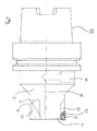
- Fig. 4 shows a three-edged reamer according to the invention.
- the tool For coupling to a machine tool, the tool has an HSK interface in the form of a standardized hollow shaft with two driving grooves.
- interchangeable cutting plates 27 are screwed into the guide rails 25 to the tool holder body.
- the interchangeable cutting plates 27 each have a cutting edge S which extends (at a low clearance angle) approximately parallel to the tool axis of rotation.
- Radial inside the indexable inserts 27 with the cutting edges S is a dashed line pressure chamber 4, which is located axially in the region of the cutting corner or cutting tip.
- the pressure chamber is connected via a connecting channel 20 with a blind hole 10 in connection.
- a pressure can be generated and introduced by a suitably selected pressure transmission means, such as hydraulic oil, in the pressure chamber.
- a suitably selected pressure transmission means such as hydraulic oil
- the Pressure chamber extends annularly over the entire circumference of the tool. Due to the uniform pressure distribution over the entire circumference, there is therefore a centering of the cutting edges S in addition to a radial positional adjustment that is equal to all cutting edges S.
- a bore 33 for a bleeding screw is furthermore provided, which communicates with the pressure chamber 4 via a branch passage 31.
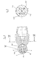
- FIG. 5 shows a reamer according to the invention with three cutting edges 27 and HSK interface 29. For clarity, only the sections of the adjusting device belonging to the two cutters facing the viewer are shown with a dashed line.
- interchangeable cutting plates 27 are screwed into guide rails 25.
- connection channels 120, 121 Due to the smaller chamber volume and the smaller amount of hydrofluid it comes to a more direct transmission of the force applied by hexagon socket screw force.
- a three-edged reamer only the two facing the viewer facing cutting S sections of the adjustment are shown in dashed line.
- the blades S are individually adjustable.
- pressure chambers 204 which are each under the guides 25, the respective cutting S are radially adjustable.
- Each pressure chamber 204 is connected via its own connection channel 220, 221 with a separate blind hole 210, 211 and thus independently of the setting of the other cutting separately pressurizable.
- the adjusting device is also suitable for stepped tools, in particular stepped reamers, in which, in addition to the cutting edges fastened on the outer circumference of the tool holder, a tool shank of an insert tool is additionally centrally clamped in a receptacle with a chuck.
- Standard chucks or shrink chucks can be used.
- the use of a Dehnspannfutters is particularly advantageous. Because with such designed finishing tools parts of the adjustment can be used simultaneously as part of the Dehnspannfutters. Step reamers in this embodiment of the invention are in the Fig. 7 to 13 shown.
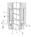
- Fig. 7 illustrated tool 300 with HSK interface 29 in this case has a hydraulic expansion chuck with two annular pressure chambers 17, in which a tool shank 13 is clamped.
- the two annular pressure chambers 17 of the hydraulic expansion chuck are connected to each other via connecting channels 45. Via a further connecting channel 321, the stretch chuck is further connected to a blind hole 310.
- the step cutting S of the step tool are formed by interchangeable cutting plates 27 which are mounted on a diameter extension of the tool in guides 25.
- the cutting edges S of the interchangeable cutting plates 27 are radially adjustable via an adjusting device, wherein the adjusting device has an annular pressure chamber 304 in the front region of the cutting S, which is connected via a connecting channel 320 with the blind hole 310.
- a centrally clampable reaming tool 50 can be clamped in the hydraulic expansion chuck.
- a tool 50 is exemplified in the Fig. 7a shown.
- the centrally clamped reamer then has the function of reaming a first stepped bore portion of small diameter, while with the cutting edges S on the diametric extension of the overall tool a second portion of the stepped bore of larger diameter is reamed.
- the step finishing tool with hydraulic chuck for machining bores in which the first drill section with a smaller diameter is relatively deep is a prerequisite to allow drilling of the bore in one operation before and after the step that the insert tool 50 is relatively long, that is, that the cutting edges 52 of the tool relatively far removed from the clamping E in the expansion chuck are.
- the expansion chuck With the expansion chuck, a well-centered clamping can be achieved, so that the concentricity error accumulating up to the tool tip is very small and long service life and low dimensional deviations can be achieved.
- the additional outlay for the expansion chuck compared to conventional chucks is limited due to the synergy effects with the adjusting device according to the invention.
- the adjustment of the radial position of the step cutting edges S serves to maintain the high dimensional accuracy in the pre-drilling section also in the region of larger diameter of the bore.
- insertion tool 50 for clamping in the central hydraulic expansion chuck of the tool according to the invention in the embodiments of Figs. 7 and 8 to 13 also provides an additional coolant supply.
- coolant Via a central cooling channel 54 along the longitudinal axis of the tool, coolant can be conducted from a coolant supply provided by the machine via distribution channels 56 to the blades 52, which exits at outlet openings 58. It is possible to use the lubricant used for cutting cooling / chip removal also for filling the pressure chambers of the adjusting device according to the invention or of the expansion chuck.
- FIGS. 8 to 11 Another embodiment of the invention Finishing tool is in the FIGS. 8 to 11 shown.
- Fig. 7 Unlike the in Fig. 7 shown embodiment of the invention is here a positional adjustment of the (three) step cutting edges regardless of the clamping pressure of Dehnspannfutters possible.
- the pressure chamber of the adjusting device is pressurized by tightening the same screw as the pressure chambers of the expansion chuck.
- two separate blind holes 410, 411 are provided for receiving pressure screws on the tool holder base body 400 thereto.
- the designated blind hole 444 is connected via a connecting channel 420 with the pressure chamber 404, while the designated blind hole 411 is connected via a further connecting channel 421 with the pressure chambers 18 of the hydraulic expansion chuck in combination. Pressure regulation on the screws thus takes place separately for hydraulic expansion chuck and adjusting device.
- the base body 400 and the sleeve 6 enclose the annular pressure chamber 404, which communicates with the blind hole 420 and a vent hole, not shown, via the channel 421 bored in the base body 400 and a vent channel.
- the pressure chamber 404 is in Fig. 11 indicated by dashed lines. As can be seen, it is located axially at the level of the cutting corner of the cutting edge S.
- the cutting edge S is formed on an indexable insert 27, which are received in a guide 25.
- the inserts are at their front end slightly over a shoulder 44 on which the expansion sleeve 6 tapers.
- the region forming the pressure chamber 404 toward the tool tip is likewise delimited by a shoulder 46.
- the shoulder 46 extends substantially in one plane with the axial cutting edge of the removable plate 27. Below the cutting corner is thus a material vulnerability 45 in the material flow of the sleeve 6. In this way, a particularly large deformation of the outer wall of the pressure chamber 404 below the Creasing corner caused while the material in the front area (the tool tip facing) of the expansion sleeve 6 decoupled from the Dehnwand.
- the sleeve 6 has on the inside at the areas 30, 40, to which it is pressed onto the tool base 400, a high surface quality in order to ensure a snug fit of the sleeve 6 on the base 400.
- a circumferential groove which is filled with solder during installation of the sleeve is and so allows a firm soldering of the sleeve 6 on the base body 400 and thus a good seal of the pressure chamber 404 to the outside.
- Fig. 12 shows a modified embodiment, the expansion sleeve 606. It is identical in essential parts with the in Fig. 11 However, shown an expansion sleeve, however, has an integrally formed in the material of the sleeve, annular pressure chamber 604, which is connected via a drilled channel 620 to a corresponding pressure medium supply and thus also on a slightly modified tool holder base body 400 would be adaptable.
- an expansion bushing 8 is inserted into the tool holder 12 in the tool holder base body 400, which is also soldered to the base body 400 and thus secured to the base body 400 sealed against the environment.
- two annular pressure chambers 18 are included, which are connected via narrow slots.
- the pressure chambers are connected via the connecting channel 421 with the blind hole 411 in connection with which thus the clamping pressure of the chuck is controlled. Due to the outside of the pressure chamber 404 and the inside of the pressure chambers 18 towards smaller wall thickness than on the side facing each other, there is only a marginal mutual influence of the two Dehnspannhydrauliken, so that the position of the blades S regardless of the clamping force of the hydraulic chuck with high Precision can be adjusted.
- a circumferential groove 25 is provided for receiving adhering to a tool shank dirt or oil residue on the inside of the expansion sleeve also still a circumferential groove 25 is provided.
- Fig. 13 shows finally an embodiment of the step finishing tool according to the invention, in which the pressure chamber 504 of the adjusting device are connected via a radially drilled connecting passage 19 with the pressure chambers 180 of the hydraulic expansion chuck.
- the outside of the tool body 500 patch expansion sleeve 506 has at its rear portion an internal thread 16, with which it can be screwed onto a corresponding external thread on the base body 500.
- a seal 15 is also provided for sealing the pressure chamber 504.
- the identifier applied as a scale can therefore only perform an iterative cutting adjustment (tightening the screw, measuring the blade adjustment) under the specified conditions at the cutting edge, tightening the screw, etc.). But even with different operating conditions, the operator gets a first indication of how far he should tighten the screw to achieve the desired cutting adjustment.
- FIG. 15 A scale described above is in Fig. 15 shown.
- an angular segment of 22.5 ° corresponds to a positional adjustment of the cutting edge by 2/1000 mm.
- the scale thus forms a linear transfer function of the screw rotation for adjusting the cutting edge ( ⁇ / e).
- Such a transfer function can quantitatively the Fig. 14 be removed. It turns out that after an initially disproportionate increase in the cutting edge adjustment per angular segment of screw revolution, it is a linear one Relation screw rotation / cutting edge adjustment (I 0 ).
- the linear range between the two points I 0 and I 1 ( ⁇ I) is on the scale of Fig. 15 displayed.
- a screw rotation of 135 ° ( ⁇ ) corresponds to a blade adjustment of 2/100 mm ( ⁇ I).
- the reference point I 0 to the measuring range is given to the operator by the fact that this is the first revolution of the screw at which he has to apply a force which exceeds a certain value.
Landscapes
- Engineering & Computer Science (AREA)
- Mechanical Engineering (AREA)
- Cutting Tools, Boring Holders, And Turrets (AREA)
- Milling, Broaching, Filing, Reaming, And Others (AREA)
- Jigs For Machine Tools (AREA)
- Milling Processes (AREA)
- Turning (AREA)
- Gripping On Spindles (AREA)
- Nonmetal Cutting Devices (AREA)
- Details Of Cutting Devices (AREA)
Applications Claiming Priority (2)
| Application Number | Priority Date | Filing Date | Title |
|---|---|---|---|
| DE20216739U DE20216739U1 (de) | 2002-10-29 | 2002-10-29 | Einstelleinrichtung für ein Feinbearbeitungswerkzeug |
| EP03023947A EP1415743B1 (fr) | 2002-10-29 | 2003-10-22 | Dispositif de réglage pour un outil de finition |
Related Parent Applications (2)
| Application Number | Title | Priority Date | Filing Date |
|---|---|---|---|
| EP03023947A Division EP1415743B1 (fr) | 2002-10-29 | 2003-10-22 | Dispositif de réglage pour un outil de finition |
| EP03023947.9 Division | 2003-10-22 |
Publications (3)
| Publication Number | Publication Date |
|---|---|
| EP2260959A2 true EP2260959A2 (fr) | 2010-12-15 |
| EP2260959A3 EP2260959A3 (fr) | 2010-12-22 |
| EP2260959B1 EP2260959B1 (fr) | 2012-10-17 |
Family
ID=32010568
Family Applications (2)
| Application Number | Title | Priority Date | Filing Date |
|---|---|---|---|
| EP10182981A Expired - Lifetime EP2260959B1 (fr) | 2002-10-29 | 2003-10-22 | Dispositif de réglage pour un outil de finissage |
| EP03023947A Expired - Lifetime EP1415743B1 (fr) | 2002-10-29 | 2003-10-22 | Dispositif de réglage pour un outil de finition |
Family Applications After (1)
| Application Number | Title | Priority Date | Filing Date |
|---|---|---|---|
| EP03023947A Expired - Lifetime EP1415743B1 (fr) | 2002-10-29 | 2003-10-22 | Dispositif de réglage pour un outil de finition |
Country Status (6)
| Country | Link |
|---|---|
| US (1) | US7140819B2 (fr) |
| EP (2) | EP2260959B1 (fr) |
| JP (2) | JP2004148495A (fr) |
| AT (1) | ATE546265T1 (fr) |
| DE (1) | DE20216739U1 (fr) |
| PL (1) | PL363095A1 (fr) |
Cited By (1)
| Publication number | Priority date | Publication date | Assignee | Title |
|---|---|---|---|---|
| WO2019170378A1 (fr) * | 2018-03-09 | 2019-09-12 | Kyocera Unimerco Tooling A/S | Outil combiné et porte-outil pour un outil combiné |
Families Citing this family (25)
| Publication number | Priority date | Publication date | Assignee | Title |
|---|---|---|---|---|
| ATE370809T1 (de) * | 2002-09-03 | 2007-09-15 | Stan C Weidmer | Werkzeug mit gezielt vorgespanntem glied und verfahren zur herstellung eines nicht achsensymmetrischen merkmals |
| FI115201B (fi) * | 2003-11-13 | 2005-03-31 | Iimu Kurikka | Monitoimiavarrin |
| DE102006005379B4 (de) * | 2006-02-03 | 2015-02-12 | Kennametal Inc. | Kombinationswerkzeug und Verfahren zur spanenden Bearbeitung eines Bohrlochs und dessen Bohrungsoberfläche |
| DE102006016290C5 (de) | 2006-04-06 | 2022-02-17 | Gühring KG | Mehrteiliges Schaftwerkzeug, insbesondere Feinbearbeitungswerkzeug |
| US7806635B2 (en) * | 2007-03-07 | 2010-10-05 | Makino, Inc. | Method and apparatus for producing a shaped bore |
| JP5703639B2 (ja) * | 2010-09-06 | 2015-04-22 | 株式会社ジェイテクト | 工具径調整装置を備える工作機械 |
| CN103747902B (zh) * | 2011-05-25 | 2016-12-07 | 大昭和精机株式会社 | 保持装置 |
| WO2013011027A1 (fr) * | 2011-07-19 | 2013-01-24 | Mauser-Werke Oberndorf Maschinenbau Gmbh | Système d'ajustement |
| CN104043849B (zh) * | 2013-03-12 | 2017-04-26 | 安加实业股份有限公司 | 用于加工异型孔的精密镗杆及应用其的数值镗孔机 |
| US20140277685A1 (en) * | 2013-03-15 | 2014-09-18 | Lai-Fa Chen | Precision boring bar and numerical control boring machine using the precision boring bar |
| EP2815837B1 (fr) * | 2013-06-19 | 2018-09-05 | Klingelnberg AG | Tête porte-lame et utilisation de celle-ci |
| CN104384934B (zh) * | 2014-09-17 | 2016-08-31 | 山东大学 | 车削-等静压滚压复合装置 |
| RU2018120852A (ru) * | 2015-11-12 | 2019-12-17 | 5ЭмИ АйПи, ЛЛК | Управление температурой расточного инструмента с криогенным охлаждением |
| EP3222375B1 (fr) * | 2016-03-24 | 2021-08-18 | Sandvik Intellectual Property AB | Outil d'alésage |
| US20180169780A1 (en) * | 2016-12-19 | 2018-06-21 | Anvil International, Llc | Cleanline threader |
| CN106735356B (zh) * | 2016-12-28 | 2019-01-08 | 基准精密工业(惠州)有限公司 | 镗刀及使用该镗刀加工孔的方法 |
| DE102017214276A1 (de) * | 2017-08-16 | 2019-02-21 | MAPAL Fabrik für Präzisionswerkzeuge Dr. Kress KG | Halter für wenigstens einen Schneidkörper zur spanenden Bearbeitung von Werkstücken |
| CN108608014A (zh) * | 2018-03-22 | 2018-10-02 | 苏州铨木智能科技有限公司 | 一种新型主轴电机的刀具定位结构及定位方式 |
| US20200001374A1 (en) * | 2018-06-29 | 2020-01-02 | Herramientas Preziss, S.L. | Cutting Insert Applicable To Machining Tools And The Tool Bearing It |
| US11364586B2 (en) | 2019-05-07 | 2022-06-21 | Tony Joseph Wensman | Device for measuring and adjusting the tool holding portion of a spindle |
| DE102020108558A1 (de) | 2020-03-27 | 2021-09-30 | Gühring KG | Hydrodehnspannfutter |
| CN113210737B (zh) * | 2021-04-30 | 2022-07-26 | 湖南大学 | 用于碳纤维复合材料的随动可调正反刃铰孔刀具 |
| US12521800B2 (en) * | 2023-07-31 | 2026-01-13 | Kennametal Inc. | Hydraulic chuck assembly and expansion sleeve therefor |
| US20250178102A1 (en) * | 2023-11-30 | 2025-06-05 | Kennametal Inc. | Pressure-activated tool |
| EP4616982A1 (fr) * | 2024-03-12 | 2025-09-17 | Gühring KG | Mandrin d'expansion hydraulique |
Citations (3)
| Publication number | Priority date | Publication date | Assignee | Title |
|---|---|---|---|---|
| DE2700934A1 (de) | 1977-01-12 | 1978-07-13 | Boerje Ramsbro | Hydraulische spannvorrichtung |
| DE9411260U1 (de) | 1993-07-13 | 1994-10-27 | Hertel AG Werkzeuge + Hartstoffe, 90766 Fürth | Spannvorrichtung für Schaftwerkzeuge |
| DE29614727U1 (de) | 1996-08-23 | 1996-10-02 | Fritz Schunk GmbH Fabrik für Spann- und Greifwerkzeuge, 74348 Lauffen | Dehnspannfutter |
Family Cites Families (27)
| Publication number | Priority date | Publication date | Assignee | Title |
|---|---|---|---|---|
| FR1432219A (fr) * | 1965-04-30 | 1966-03-18 | Procédé pour l'usinage micrométrique de pièces quelconques, tout dispositif pourla mise en application du présent procédé ou procédé similaire, ainsi que les machines-outils ou autres appareils de précision pourvus du présent dispositif | |
| GB1125054A (en) * | 1966-03-10 | 1968-08-28 | Fagersta Bruks Ab | Improvements relating to radial fine adjustment of the cutting edge of a tool |
| DE2804698C2 (de) | 1978-02-03 | 1982-08-12 | Samson Ag, 6000 Frankfurt | Bohrkopf |
| IT1143388B (it) * | 1981-02-12 | 1986-10-22 | Workmen Machine Tools S C R L | Dispositivo di compensazione dell usura dell utensile per macchine utensili particolarmente per macchine alesatrici |
| DE3630126A1 (de) * | 1985-09-09 | 1987-03-12 | St Etienne Mach Outil | Bohrgeraet |
| JPH067587B2 (ja) * | 1986-09-01 | 1994-01-26 | 三菱電機株式会社 | 固体撮像装置 |
| JPS6360561U (fr) * | 1986-10-13 | 1988-04-22 | ||
| DE3721521A1 (de) * | 1987-06-30 | 1989-01-12 | Schunk Fritz Gmbh | Werkzeug-spannsystem |
| US4941782A (en) * | 1988-12-30 | 1990-07-17 | Gte Valenite Corporation | Adjustable boring bar |
| JPH02130715U (fr) * | 1989-03-31 | 1990-10-29 | ||
| JPH035414U (fr) * | 1989-06-05 | 1991-01-21 | ||
| JPH0366562A (ja) * | 1989-07-31 | 1991-03-22 | Honda Motor Co Ltd | ホーニング用工具 |
| DE4015149A1 (de) * | 1990-05-11 | 1991-11-14 | Renate Ruf | Dehnspannfutter |
| DE4401496C3 (de) * | 1994-01-20 | 2001-07-26 | Emag Maschfab Gmbh | Werkzeugschneiden-Verstelleinrichtung zum Bearbeiten von runden, unrunden und/oder nicht zylinderförmigen Innen- und/oder Außenkonturen |
| US5427480A (en) * | 1994-04-25 | 1995-06-27 | Valenite Inc. | Boring tool having an adjustable cutter element |
| JPH07329053A (ja) * | 1994-06-07 | 1995-12-19 | Mitsubishi Materials Corp | スライシングマシン |
| DE4447558C5 (de) * | 1994-08-25 | 2004-04-29 | Gühring, Jörg, Dr. | Rundlaufendes Werkzeug |
| US5516243A (en) * | 1995-01-03 | 1996-05-14 | Hydra-Lock Corporation | Reamer chuck and tool expander |
| DE19540374C2 (de) * | 1995-10-30 | 1999-10-28 | Mapal Fab Praezision | Bohrstange zum Bearbeiten von in axialer Richtung in einem Abstand zueinander angeordneten Bohrungsoberflächen |
| JP4089796B2 (ja) * | 1997-09-24 | 2008-05-28 | アスカトレーディング株式会社 | 裏座ぐり・面取り加工装置 |
| US6270295B1 (en) * | 1998-09-08 | 2001-08-07 | Makino, Inc. | Tool with selectively biased member and method of using the same |
| US6536998B2 (en) | 1998-09-08 | 2003-03-25 | Makino, Inc. | Selectively biased tool and methods of using the same |
| US6243962B1 (en) * | 1999-02-10 | 2001-06-12 | Samsomatic, Ltd. | Boring apparatus with shaft mounted diameter gage |
| US6247878B1 (en) * | 1999-10-12 | 2001-06-19 | Kennametal Pc Inc. | Device and method for adjusting the position of cutting inserts mounted in a cutting tool |
| WO2003013769A2 (fr) * | 2001-08-08 | 2003-02-20 | Johne + Co. Präzisionswerkzeuge Gmbh | Outil rotatif a plusieurs tranchants |
| US6846136B2 (en) * | 2002-08-06 | 2005-01-25 | Velenite Inc. | Rotatable cutting tool |
| US20050044686A1 (en) * | 2003-08-25 | 2005-03-03 | Huijbers Johannes W. G. M. | Hydraulically actuated holder |
-
2002
- 2002-10-29 DE DE20216739U patent/DE20216739U1/de not_active Expired - Lifetime
-
2003
- 2003-10-22 EP EP10182981A patent/EP2260959B1/fr not_active Expired - Lifetime
- 2003-10-22 EP EP03023947A patent/EP1415743B1/fr not_active Expired - Lifetime
- 2003-10-22 AT AT03023947T patent/ATE546265T1/de active
- 2003-10-24 PL PL03363095A patent/PL363095A1/xx unknown
- 2003-10-27 JP JP2003365923A patent/JP2004148495A/ja active Pending
- 2003-10-29 US US10/696,152 patent/US7140819B2/en not_active Expired - Lifetime
-
2010
- 2010-12-22 JP JP2010285413A patent/JP5420528B2/ja not_active Expired - Fee Related
Patent Citations (3)
| Publication number | Priority date | Publication date | Assignee | Title |
|---|---|---|---|---|
| DE2700934A1 (de) | 1977-01-12 | 1978-07-13 | Boerje Ramsbro | Hydraulische spannvorrichtung |
| DE9411260U1 (de) | 1993-07-13 | 1994-10-27 | Hertel AG Werkzeuge + Hartstoffe, 90766 Fürth | Spannvorrichtung für Schaftwerkzeuge |
| DE29614727U1 (de) | 1996-08-23 | 1996-10-02 | Fritz Schunk GmbH Fabrik für Spann- und Greifwerkzeuge, 74348 Lauffen | Dehnspannfutter |
Non-Patent Citations (1)
| Title |
|---|
| "Hoher, schneller, weiter..", January 2002, FIRMA HAUSER HSC-TECHNOLOGIE, article "Ausgabe 01/2002" |
Cited By (1)
| Publication number | Priority date | Publication date | Assignee | Title |
|---|---|---|---|---|
| WO2019170378A1 (fr) * | 2018-03-09 | 2019-09-12 | Kyocera Unimerco Tooling A/S | Outil combiné et porte-outil pour un outil combiné |
Also Published As
| Publication number | Publication date |
|---|---|
| JP2004148495A (ja) | 2004-05-27 |
| US7140819B2 (en) | 2006-11-28 |
| JP5420528B2 (ja) | 2014-02-19 |
| ATE546265T1 (de) | 2012-03-15 |
| EP2260959A3 (fr) | 2010-12-22 |
| EP1415743B1 (fr) | 2012-02-22 |
| JP2011088272A (ja) | 2011-05-06 |
| DE20216739U1 (de) | 2004-03-11 |
| PL363095A1 (en) | 2004-05-04 |
| US20040191022A1 (en) | 2004-09-30 |
| EP1415743A1 (fr) | 2004-05-06 |
| EP2260959B1 (fr) | 2012-10-17 |
Similar Documents
| Publication | Publication Date | Title |
|---|---|---|
| EP1415743B1 (fr) | Dispositif de réglage pour un outil de finition | |
| EP1602426B1 (fr) | Dispositif de serrage pour la fixation avec positionnement précis d'une pince de serrage sur un mandrin | |
| EP2855059B1 (fr) | Porte-outil modulaire | |
| EP2536531B2 (fr) | Machine-outil et procédé pour l'usinage d'une pièce | |
| DE19548366C2 (de) | Werkzeughalter, auch als Feinbearbeitungswerkzeug | |
| DE102006016290B4 (de) | Mehrteiliges Schaftwerkzeug, insbesondere Feinbearbeitungswerkzeug | |
| EP2349622B1 (fr) | Outil de finition d'alésage par enlèvement de copeaux, à plusieurs tranchants | |
| DE102005007038B4 (de) | Werkstückspindelstock | |
| DE2804698A1 (de) | Umlaufender bohrkopf mit verstellbarem schneidwerkzeug | |
| WO2005044489A1 (fr) | Manchon intermediaire pour mandrin de serrage et procede de production correspondant | |
| EP3509781B1 (fr) | Outil d'usinage par enlèvement de copeaux multi-lames et procédé d'usinage d'une demi-ligne | |
| WO2010006966A1 (fr) | Outil comportant un dispositif de fixation | |
| DE102018120739A1 (de) | Schreib-Gravier-Werkzeughalter | |
| EP2001625A1 (fr) | Dispositif de serrage pour outils ou pieces en rotaion | |
| EP3991892A1 (fr) | Outil d'enlèvement de matière doté d'un dispositif de réglage | |
| DE3630126A1 (de) | Bohrgeraet | |
| EP1718430A2 (fr) | Procede d'usinage par enlevement de copeaux de trous de precision | |
| EP3658320B1 (fr) | Outil d'usinage par enlèvement de copeaux doté d'un dispositif de réglage | |
| DE102012222574B4 (de) | Rundlaufwerkzeug, insbesondere Reibwerkzeug sowie Verstellelement für ein Rundlaufwerkzeug | |
| DE19721997A1 (de) | Maschinenwerkzeug zur spanabhebenden Bearbeitung von Werkstücken | |
| EP1360024B1 (fr) | Tete de percage de precision a deplacement radial sans jeu | |
| DE102017120308A1 (de) | Werkzeughalter zur Aufnahme eines Werkzeugkopfes | |
| EP0327818A1 (fr) | Dispositif de fraisage et de chanfreinage | |
| DE3524434C1 (de) | Werkzeugmaschinenspindel und hierzu passende Werkzeughalter | |
| EP0688621A1 (fr) | Foret |
Legal Events
| Date | Code | Title | Description |
|---|---|---|---|
| PUAI | Public reference made under article 153(3) epc to a published international application that has entered the european phase |
Free format text: ORIGINAL CODE: 0009012 |
|
| PUAL | Search report despatched |
Free format text: ORIGINAL CODE: 0009013 |
|
| AC | Divisional application: reference to earlier application |
Ref document number: 1415743 Country of ref document: EP Kind code of ref document: P |
|
| AK | Designated contracting states |
Kind code of ref document: A2 Designated state(s): AT BE BG CH CY CZ DE DK EE ES FI FR GB GR HU IE IT LI LU MC NL PT RO SE SI SK TR |
|
| AK | Designated contracting states |
Kind code of ref document: A3 Designated state(s): AT BE BG CH CY CZ DE DK EE ES FI FR GB GR HU IE IT LI LU MC NL PT RO SE SI SK TR |
|
| 17P | Request for examination filed |
Effective date: 20110622 |
|
| 17Q | First examination report despatched |
Effective date: 20110907 |
|
| GRAP | Despatch of communication of intention to grant a patent |
Free format text: ORIGINAL CODE: EPIDOSNIGR1 |
|
| GRAS | Grant fee paid |
Free format text: ORIGINAL CODE: EPIDOSNIGR3 |
|
| GRAA | (expected) grant |
Free format text: ORIGINAL CODE: 0009210 |
|
| AC | Divisional application: reference to earlier application |
Ref document number: 1415743 Country of ref document: EP Kind code of ref document: P |
|
| AK | Designated contracting states |
Kind code of ref document: B1 Designated state(s): AT BE BG CH CY CZ DE DK EE ES FI FR GB GR HU IE IT LI LU MC NL PT RO SE SI SK TR |
|
| REG | Reference to a national code |
Ref country code: GB Ref legal event code: FG4D Free format text: NOT ENGLISH |
|
| REG | Reference to a national code |
Ref country code: CH Ref legal event code: EP |
|
| REG | Reference to a national code |
Ref country code: IE Ref legal event code: FG4D Free format text: LANGUAGE OF EP DOCUMENT: GERMAN |
|
| REG | Reference to a national code |
Ref country code: AT Ref legal event code: REF Ref document number: 579656 Country of ref document: AT Kind code of ref document: T Effective date: 20121115 |
|
| REG | Reference to a national code |
Ref country code: DE Ref legal event code: R096 Ref document number: 50314547 Country of ref document: DE Effective date: 20121213 |
|
| REG | Reference to a national code |
Ref country code: NL Ref legal event code: VDEP Effective date: 20121017 |
|
| BERE | Be: lapsed |
Owner name: GUHRING, JORG, DR. Effective date: 20121031 |
|
| PG25 | Lapsed in a contracting state [announced via postgrant information from national office to epo] |
Ref country code: SE Free format text: LAPSE BECAUSE OF FAILURE TO SUBMIT A TRANSLATION OF THE DESCRIPTION OR TO PAY THE FEE WITHIN THE PRESCRIBED TIME-LIMIT Effective date: 20121017 Ref country code: FI Free format text: LAPSE BECAUSE OF FAILURE TO SUBMIT A TRANSLATION OF THE DESCRIPTION OR TO PAY THE FEE WITHIN THE PRESCRIBED TIME-LIMIT Effective date: 20121017 Ref country code: NL Free format text: LAPSE BECAUSE OF FAILURE TO SUBMIT A TRANSLATION OF THE DESCRIPTION OR TO PAY THE FEE WITHIN THE PRESCRIBED TIME-LIMIT Effective date: 20121017 Ref country code: ES Free format text: LAPSE BECAUSE OF FAILURE TO SUBMIT A TRANSLATION OF THE DESCRIPTION OR TO PAY THE FEE WITHIN THE PRESCRIBED TIME-LIMIT Effective date: 20130128 |
|
| PG25 | Lapsed in a contracting state [announced via postgrant information from national office to epo] |
Ref country code: MC Free format text: LAPSE BECAUSE OF NON-PAYMENT OF DUE FEES Effective date: 20121031 Ref country code: PT Free format text: LAPSE BECAUSE OF FAILURE TO SUBMIT A TRANSLATION OF THE DESCRIPTION OR TO PAY THE FEE WITHIN THE PRESCRIBED TIME-LIMIT Effective date: 20130218 Ref country code: GR Free format text: LAPSE BECAUSE OF FAILURE TO SUBMIT A TRANSLATION OF THE DESCRIPTION OR TO PAY THE FEE WITHIN THE PRESCRIBED TIME-LIMIT Effective date: 20130118 Ref country code: SI Free format text: LAPSE BECAUSE OF FAILURE TO SUBMIT A TRANSLATION OF THE DESCRIPTION OR TO PAY THE FEE WITHIN THE PRESCRIBED TIME-LIMIT Effective date: 20121017 |
|
| REG | Reference to a national code |
Ref country code: CH Ref legal event code: PL |
|
| REG | Reference to a national code |
Ref country code: IE Ref legal event code: MM4A |
|
| PG25 | Lapsed in a contracting state [announced via postgrant information from national office to epo] |
Ref country code: BE Free format text: LAPSE BECAUSE OF NON-PAYMENT OF DUE FEES Effective date: 20121031 Ref country code: CZ Free format text: LAPSE BECAUSE OF FAILURE TO SUBMIT A TRANSLATION OF THE DESCRIPTION OR TO PAY THE FEE WITHIN THE PRESCRIBED TIME-LIMIT Effective date: 20121017 Ref country code: SK Free format text: LAPSE BECAUSE OF FAILURE TO SUBMIT A TRANSLATION OF THE DESCRIPTION OR TO PAY THE FEE WITHIN THE PRESCRIBED TIME-LIMIT Effective date: 20121017 Ref country code: LI Free format text: LAPSE BECAUSE OF NON-PAYMENT OF DUE FEES Effective date: 20121031 Ref country code: DK Free format text: LAPSE BECAUSE OF FAILURE TO SUBMIT A TRANSLATION OF THE DESCRIPTION OR TO PAY THE FEE WITHIN THE PRESCRIBED TIME-LIMIT Effective date: 20121017 Ref country code: CH Free format text: LAPSE BECAUSE OF NON-PAYMENT OF DUE FEES Effective date: 20121031 Ref country code: IE Free format text: LAPSE BECAUSE OF NON-PAYMENT OF DUE FEES Effective date: 20121022 Ref country code: BG Free format text: LAPSE BECAUSE OF FAILURE TO SUBMIT A TRANSLATION OF THE DESCRIPTION OR TO PAY THE FEE WITHIN THE PRESCRIBED TIME-LIMIT Effective date: 20130117 Ref country code: EE Free format text: LAPSE BECAUSE OF FAILURE TO SUBMIT A TRANSLATION OF THE DESCRIPTION OR TO PAY THE FEE WITHIN THE PRESCRIBED TIME-LIMIT Effective date: 20121017 |
|
| PLBE | No opposition filed within time limit |
Free format text: ORIGINAL CODE: 0009261 |
|
| STAA | Information on the status of an ep patent application or granted ep patent |
Free format text: STATUS: NO OPPOSITION FILED WITHIN TIME LIMIT |
|
| PG25 | Lapsed in a contracting state [announced via postgrant information from national office to epo] |
Ref country code: RO Free format text: LAPSE BECAUSE OF FAILURE TO SUBMIT A TRANSLATION OF THE DESCRIPTION OR TO PAY THE FEE WITHIN THE PRESCRIBED TIME-LIMIT Effective date: 20121017 Ref country code: IT Free format text: LAPSE BECAUSE OF FAILURE TO SUBMIT A TRANSLATION OF THE DESCRIPTION OR TO PAY THE FEE WITHIN THE PRESCRIBED TIME-LIMIT Effective date: 20121017 |
|
| REG | Reference to a national code |
Ref country code: FR Ref legal event code: ST Effective date: 20130805 |
|
| 26N | No opposition filed |
Effective date: 20130718 |
|
| GBPC | Gb: european patent ceased through non-payment of renewal fee |
Effective date: 20130117 |
|
| REG | Reference to a national code |
Ref country code: DE Ref legal event code: R097 Ref document number: 50314547 Country of ref document: DE Effective date: 20130718 |
|
| PG25 | Lapsed in a contracting state [announced via postgrant information from national office to epo] |
Ref country code: FR Free format text: LAPSE BECAUSE OF NON-PAYMENT OF DUE FEES Effective date: 20121217 Ref country code: GB Free format text: LAPSE BECAUSE OF NON-PAYMENT OF DUE FEES Effective date: 20130117 Ref country code: CY Free format text: LAPSE BECAUSE OF FAILURE TO SUBMIT A TRANSLATION OF THE DESCRIPTION OR TO PAY THE FEE WITHIN THE PRESCRIBED TIME-LIMIT Effective date: 20121017 |
|
| REG | Reference to a national code |
Ref country code: AT Ref legal event code: MM01 Ref document number: 579656 Country of ref document: AT Kind code of ref document: T Effective date: 20121031 |
|
| PG25 | Lapsed in a contracting state [announced via postgrant information from national office to epo] |
Ref country code: AT Free format text: LAPSE BECAUSE OF NON-PAYMENT OF DUE FEES Effective date: 20121031 |
|
| PG25 | Lapsed in a contracting state [announced via postgrant information from national office to epo] |
Ref country code: TR Free format text: LAPSE BECAUSE OF FAILURE TO SUBMIT A TRANSLATION OF THE DESCRIPTION OR TO PAY THE FEE WITHIN THE PRESCRIBED TIME-LIMIT Effective date: 20121017 |
|
| PG25 | Lapsed in a contracting state [announced via postgrant information from national office to epo] |
Ref country code: LU Free format text: LAPSE BECAUSE OF NON-PAYMENT OF DUE FEES Effective date: 20121022 |
|
| PG25 | Lapsed in a contracting state [announced via postgrant information from national office to epo] |
Ref country code: HU Free format text: LAPSE BECAUSE OF FAILURE TO SUBMIT A TRANSLATION OF THE DESCRIPTION OR TO PAY THE FEE WITHIN THE PRESCRIBED TIME-LIMIT Effective date: 20031022 |
|
| PGFP | Annual fee paid to national office [announced via postgrant information from national office to epo] |
Ref country code: DE Payment date: 20221031 Year of fee payment: 20 |
|
| REG | Reference to a national code |
Ref country code: DE Ref legal event code: R071 Ref document number: 50314547 Country of ref document: DE |