EP2267664A2 - Système de fermeture et procédure pour l'échange de données dans un système de fermeture - Google Patents
Système de fermeture et procédure pour l'échange de données dans un système de fermeture Download PDFInfo
- Publication number
- EP2267664A2 EP2267664A2 EP10176937A EP10176937A EP2267664A2 EP 2267664 A2 EP2267664 A2 EP 2267664A2 EP 10176937 A EP10176937 A EP 10176937A EP 10176937 A EP10176937 A EP 10176937A EP 2267664 A2 EP2267664 A2 EP 2267664A2
- Authority
- EP
- European Patent Office
- Prior art keywords
- node device
- closure
- closing
- central
- node
- Prior art date
- Legal status (The legal status is an assumption and is not a legal conclusion. Google has not performed a legal analysis and makes no representation as to the accuracy of the status listed.)
- Granted
Links
- 238000000034 method Methods 0.000 title claims abstract description 8
- 230000005540 biological transmission Effects 0.000 claims description 19
- 230000004044 response Effects 0.000 claims description 7
- 238000013475 authorization Methods 0.000 description 4
- 238000007689 inspection Methods 0.000 description 4
- 238000009434 installation Methods 0.000 description 4
- 230000004308 accommodation Effects 0.000 description 3
- 238000010276 construction Methods 0.000 description 3
- 230000035484 reaction time Effects 0.000 description 3
- 230000008901 benefit Effects 0.000 description 2
- 238000004891 communication Methods 0.000 description 2
- 238000012790 confirmation Methods 0.000 description 2
- 238000010586 diagram Methods 0.000 description 2
- 230000009471 action Effects 0.000 description 1
- 230000004913 activation Effects 0.000 description 1
- 230000006978 adaptation Effects 0.000 description 1
- 230000008859 change Effects 0.000 description 1
- 230000001934 delay Effects 0.000 description 1
- 230000001419 dependent effect Effects 0.000 description 1
- 230000005611 electricity Effects 0.000 description 1
- 238000005516 engineering process Methods 0.000 description 1
- 239000002184 metal Substances 0.000 description 1
- 238000012544 monitoring process Methods 0.000 description 1
- 239000011150 reinforced concrete Substances 0.000 description 1
- 230000008672 reprogramming Effects 0.000 description 1
- 238000012163 sequencing technique Methods 0.000 description 1
- 238000012546 transfer Methods 0.000 description 1
- 230000001960 triggered effect Effects 0.000 description 1
- 238000011144 upstream manufacturing Methods 0.000 description 1
Images
Classifications
-
- G—PHYSICS
- G07—CHECKING-DEVICES
- G07C—TIME OR ATTENDANCE REGISTERS; REGISTERING OR INDICATING THE WORKING OF MACHINES; GENERATING RANDOM NUMBERS; VOTING OR LOTTERY APPARATUS; ARRANGEMENTS, SYSTEMS OR APPARATUS FOR CHECKING NOT PROVIDED FOR ELSEWHERE
- G07C9/00—Individual registration on entry or exit
- G07C9/20—Individual registration on entry or exit involving the use of a pass
- G07C9/27—Individual registration on entry or exit involving the use of a pass with central registration
-
- G—PHYSICS
- G07—CHECKING-DEVICES
- G07C—TIME OR ATTENDANCE REGISTERS; REGISTERING OR INDICATING THE WORKING OF MACHINES; GENERATING RANDOM NUMBERS; VOTING OR LOTTERY APPARATUS; ARRANGEMENTS, SYSTEMS OR APPARATUS FOR CHECKING NOT PROVIDED FOR ELSEWHERE
- G07C9/00—Individual registration on entry or exit
- G07C9/20—Individual registration on entry or exit involving the use of a pass
- G07C9/28—Individual registration on entry or exit involving the use of a pass the pass enabling tracking or indicating presence
Definitions
- the invention relates to a locking system and a method for data exchange in a locking system.
- doors are provided with an electric door opener in conventional locking systems.
- an identification device such as a handset (transponder), for example in the form and size of a credit card, must be held in proximity or directly to the reader.
- the door is then released.
- the various readers are connected via corresponding lines with a central control unit.
- This central control unit contains the necessary authorization information for each door and, if the request is justified, releases the door to be opened.
- the doors are connected via corresponding lines to the central control unit, so that an opening signal from this can be transmitted directly to the door.
- the readers and the doors are therefore connected via corresponding data lines in a star shape with the central control unit.
- Such a conventional locking system is disadvantageous in three respects.
- the doors of the building to be connected to the control unit by means of cables.
- battery-operated locks ie locks
- the closure is adapted to suit.
- cabling with a central control unit for power and data exchange is no longer required.
- Such a closure can also be retrofitted into existing doors.
- a corresponding transponder communicates, for example, by radio directly with the closure of the door to be opened.
- the invention has for its object to provide a locking system that allows easy and fast data exchange for programming and monitoring of the individual locks, as well as to provide a method for data exchange in a locking system. This object is achieved with the features of the claims.
- the invention is based on the basic idea of communicating with a closure via a locking node device (local node).
- a closing node device is arranged in the immediate vicinity of the associated closure, since the battery-operated closure can and should transmit low-energy with only a short range.
- These lock-node devices are connected by radio transmission to a central node device (central node).
- central node central node
- any desired closing node device can be controlled by this central node device by means of radio transmission, and the closure can be programmed or read out via this.
- the controlled closing node device also communicates by means of radio transmission with its assigned and to be programmed or to be controlled closure.
- At least one master node device is provided for data transmission between the central node device and the at least one closing node device Node.
- one or more pilot node devices can be interposed between the central node device and a closing node device arranged far away from it.
- the data is then forwarded from the central node device to the first guide node device, from there on to a possibly next guide node device as far as the control node device to be triggered.
- a Leitknoten intensity can also work as a closing node device (Leit-Schuiteknoten intensity).
- the central node device preferably forms the network interface to a central computer, for example a central control unit such as a PC, from which the individual locks are programmed or controlled and read out.
- a central computer for example a central control unit such as a PC, from which the individual locks are programmed or controlled and read out.
- the Leitknoten prepareden are provided for a transfer of the data packets in the network of locking system. Their power supply is preferably via a power supply. In a preferred embodiment, the Leitknoten prepareden can be easily plugged into existing sockets.
- the locking node devices form battery-powered network interfaces to the individual locks in the doors.
- the lock node devices are most of the time in an energy-saving sleep mode and are addressed with special wake-up frames.
- a closing node device is preferably of modular construction, specifically of the following three modules: 1. For data transmission between the closing node device and the central node device or a routing node device, a radio connection device, preferably a GranJansen module and an antenna is provided, which transmits the radio traffic at a frequency of, for example 430 MHz or alternatively 868 MHz controls; 2. for the data exchange between the closing node device and a closure, a second short-range radio connection device, for example a micro configuration device ( ⁇ CD) as programming protocol interface for a data transmission with the frequency of 25 kHz and also an antenna is provided; 3.
- a radio connection device preferably a GranJansen module and an antenna
- a second short-range radio connection device for example a micro configuration device ( ⁇ CD) as programming protocol interface for a data transmission with the frequency of 25 kHz and also an antenna is provided.
- ⁇ CD micro configuration device
- a node control device is provided as an interface adapter between the first radio connection device (the GranJansen module) and the second radio connection device (the microconfiguration device) (WaveNet Controller). These three modules are preferably operated with a 3V power supply. On the one hand, this construction makes it possible to bridge long distances between the closing node device and the central node device, but on the other hand, to control the closure through its metal housing at a short distance.
- the node device is a central node device, a Leitknoten addressed, a Leit-Sch Stammknoten Road, or a Sch Häknoten Road. This preferably recognizes the control of the node device automatically.
- the ⁇ CD remains unpopulated, the power supply via a power supply, and the node device has a V24 interface adapter.
- a closing node device has a micro-configuration device (for data exchange with the closure) and the power supply is via a battery.
- the node device For operation as a routing node device, the node device has neither ⁇ CD nor a V24 interface adapter, the power supply takes place here via a power supply.
- a lead-lock node device has a micro-configuration device, as well as a power supply for power supply.
- An advantage of the system according to the invention is the ease of installation of the entire network in the building, without the need for preconfiguration of the system or installations on the building. This also makes it possible to retrofit existing locking systems with decentralized access control.
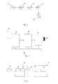
- FIG. 1 shows a basic structure of the system according to the invention for data exchange. This in FIG. 1 Example shown has a closing node device 1, a central node device 2 and three intermediate node devices 3 connected therebetween.
- FIG. 2 shows a Blockschlaltsent the basic structure of a closing node device.
- This has a first radio connection device 11, to which an antenna 12 is connected.
- the closing node device communicates with its upstream node control devices (Leiknoten addressed, central node device).
- the closing node device has a second radio connection device 13 and an antenna 14 connected to it.
- the two radio connection devices are controlled by a node control device 15. This also serves as an interface for the data transmission between the two radio link devices.
- FIG. 2 still a power supply 16. This is preferably a battery in the case of a closing node device.
- the data is transmitted between the various node devices using a 430 MHz multichannel transceiver from Gran Jansen.
- the module GranJansenPP400 is preferably used.
- the range of this module is highly dependent on the degree of shielding of the environment. Thus, if there is line of sight, several 100 meters range can be achieved. In a reinforced concrete construction, however, the range can fall to values between 30 and 100 meters.
- the power supply of this module takes place in a closing node device via a battery 16 of the closing node device 1. This allows a cabling-free attachment near the door.
- the antenna can be accommodated in the housing of the node device.
- the controller 15 (WaveNet Controller) is the master controller for the GranJansen module 11 and the micro-configuration device 13. It is responsible for node sequencing.
- the most important task of the WaveNet controller is an interface adaptation between the GranJansen module and the locking system (s) 4 (Lock Data Base) or ⁇ CD. The purpose of this is to ensure the widest possible compatibility with existing LinkPower software for locking system management and ⁇ CD.
- the life of the battery 16 in a closing node device 1 is several years.
- the closing node device 1 is switched after completion of a data exchange in a sleep state and woken up when needed.
- chaining of the node devices and long sleep periods causes long delays, a compromise between the idle time and the response time is required.
- the time until the module detects whether a message is currently being sent is 100 ms. If an AA battery (about 2, lAh) is used at a Rx power consumption of 17mA, with a lifetime of e.g. 10a the ratio 1: 647 corresponding to 64s reaction time.
- It is preferable to use a 3V battery as it can be connected directly to the input of the module.
- the otherwise required voltage regulator causes 20 ⁇ A power consumption.
- a woken node device remains awake according to the invention for about 1 minute to keep the response time of the response as small as possible.
- relationship 1 1000 1: 500 1: 250 1: 100 1:50 1:10 Response time per node device 100s 50s 25s 10s 5s 1s lifespan 15,4a 7,7a 3,86a 1,5- 0,77a 0.15A
- reaction time in the range of 25 s is preferred.
- One way to achieve shorter response times is to power the node devices 3 via power supplies. The Leitknoten Painen 3 can thus remain constantly in readiness to receive.
- All programming protocols of the closures run according to the invention in the background and without confirmation. That is, the user changes in the central control unit e.g. the locking plan of the locking system, arranges the programming of the new locking plan and only gets the message that the programming is done. Only when problems occur during programming will the user be notified accordingly (e.g., Node Device will not respond).
- the central control unit e.g. the locking plan of the locking system
- the access list is preferably buffered. It is e.g. Updated every hour by the node device (only if on-site inspection took place).
- the transponder list is also read from a buffer. Preference is given to give the opportunity to read the data from the lock cylinder at any time.
- a reporting of each individual door inspection to the central control unit preferably does not take place in order to protect the battery, but is possible for node devices which are over Power supplies are supplied externally. Likewise, alarm generation and regular reporting are preferably dispensed with.
- the closing node devices 1 are preferably configured for even longer periods of rest when the locking system administration 4 (Lock Data Base) is closed (approximately 1: 500).
- the attachment in the door by means of a cartridge which receives the battery and other hardware.
- the attachment in the door by means of cartridge has the advantage that this allows a constant radio communication with the closure, regardless of the opening state of the door, since the spatial distance closure - closing node device remains constant. Furthermore, such a cartridge with a hole in the door leaf is easy to install and there is a high sabotage / Vandalismusschreib.
- each closing node device 1 It is advantageous to equip each closing node device 1 with an externally visible light-emitting diode. During installation, an interruption of the radio contact to the central node device 2 can be indicated by this LED. The user can thus see relatively quickly why the data transmission in the network is not working. During operation can be given with the help of the LED eg a battery warning.
- the central node device 2 is constructed like a normal node device. Instead of a battery, the central node device has a V24 plug, via which also the power supply (12V) takes place.
- the central node device is preferably plugged directly into one of the COM ports of the control PC. As a housing dongle housing is preferably used.
- the following technical data of the central node device are preferred: - Frequency: 433.92 MHz - output power: 6 mW - Min. Voltage: 3V (voltage regulator 5-9V is integrated) - Power consumption at RX 17mA - Electricity consumption at TX 28mA - size 30 x 40 x 15 mm - Wake up timer integrated (100ms to months) - 32 freely programmable channels - 4 different modes - There are 254 bytes of EEPROM available for user-specific purposes
- a suitable address stack is inserted in the data field of the data packets to be transmitted (together with information about the length of the stack, whether the data packet is on the outward or return journey).
- This address stack describes an exact path from the central node device 2 over a maximum of 32 Leitknoten Nur 3 to be driven to the locking node device 1.
- this address stack is rotated. It is inverted at the destination, so that the acknowledgment can run back the same path from the closing node device 1 to the central node device 2.
- the address stack for a data transmission from the central node device CN (sender or source) via the routing node devices RN1 and RN2 to the closing node device LN3 is as follows: CN RN1 RN2 LN3 message
- the operation of the address stack, the address rotation and the path reversal are illustrated concretely in the following example.
- This address stack is now always placed in the data packets before the actual message (data for the closing node device).
- the addresses are rotated.
- the source address is always in the first place (after specifying the size of the packet) and immediately afterwards the destination address.
- a packet is encountered at the destination when the central node device appears as the next destination address.
- the transmission of the V24 frame to the micro-configuration device takes place, which executes the corresponding programming protocols with the closure.
- the path direction is reversed and the ⁇ CD acknowledgment packet is run back on the same path back to the central node device.
- the closing node device LN187 recognizes that this packet is destined for it (next destination address is CN) and therefore passes the message (V24-frame) to the V24 Mirko configuration device interface.
- the Mirko configuration device then executes the appropriate programming protocols.
- This signal is obviously intended for the central node device, which receives it and passes the content to the locking system management software. If there is an unsuccessful attempt to send on the way there, the path reversal takes place there, where the confirmation on the attempt to send failed. The package will then go unreconstructed back to the central node device, where the lock management then take appropriate action (for example, try another attempt on the same path or another path).
- the data transmission or the activation of the node devices preferably takes place with the short-range radio technology Bluetooth.
- Bluetooth is the name of a new data transmission standard that enables the wireless connection of electronic devices via short-range radio.
- the individual node devices in particular the locking node devices with corresponding Bluetooth modules, d. H. Transmit and receive chips provided.
- Bluetooth transceivers also allow communication with other electronic devices, such. B. with a mobile phone, so that on-site closure, for example, with a "Bluetooth" phone can be opened.
- the data exchange from mobile phone to the closing node device.
- the closing node device then controls the closure.
- this data transmission takes place in the locking system according to the invention with a frequency of about 2.4 GHz.
Landscapes
- Physics & Mathematics (AREA)
- General Physics & Mathematics (AREA)
- Lock And Its Accessories (AREA)
- Small-Scale Networks (AREA)
Applications Claiming Priority (2)
| Application Number | Priority Date | Filing Date | Title |
|---|---|---|---|
| DE10011035A DE10011035C2 (de) | 2000-03-07 | 2000-03-07 | Schließanlagensystem und Verfahren zum Datenaustausch in einem Schließanlagensystem |
| EP01103644A EP1132871A3 (fr) | 2000-03-07 | 2001-02-22 | Système de fermeture et procédure pour l'échange de données dans un système de fermeture |
Related Parent Applications (2)
| Application Number | Title | Priority Date | Filing Date |
|---|---|---|---|
| EP01103644A Division EP1132871A3 (fr) | 2000-03-07 | 2001-02-22 | Système de fermeture et procédure pour l'échange de données dans un système de fermeture |
| EP01103644.9 Division | 2001-02-22 |
Publications (3)
| Publication Number | Publication Date |
|---|---|
| EP2267664A2 true EP2267664A2 (fr) | 2010-12-29 |
| EP2267664A3 EP2267664A3 (fr) | 2015-08-19 |
| EP2267664B1 EP2267664B1 (fr) | 2018-08-22 |
Family
ID=7633808
Family Applications (2)
| Application Number | Title | Priority Date | Filing Date |
|---|---|---|---|
| EP10176937.0A Expired - Lifetime EP2267664B1 (fr) | 2000-03-07 | 2001-02-22 | Système de fermeture et procédure pour l'échange de données dans un système de fermeture |
| EP01103644A Ceased EP1132871A3 (fr) | 2000-03-07 | 2001-02-22 | Système de fermeture et procédure pour l'échange de données dans un système de fermeture |
Family Applications After (1)
| Application Number | Title | Priority Date | Filing Date |
|---|---|---|---|
| EP01103644A Ceased EP1132871A3 (fr) | 2000-03-07 | 2001-02-22 | Système de fermeture et procédure pour l'échange de données dans un système de fermeture |
Country Status (2)
| Country | Link |
|---|---|
| EP (2) | EP2267664B1 (fr) |
| DE (1) | DE10011035C2 (fr) |
Families Citing this family (6)
| Publication number | Priority date | Publication date | Assignee | Title |
|---|---|---|---|---|
| DE10246668A1 (de) * | 2002-10-07 | 2004-04-22 | Dorma Gmbh + Co. Kg | Zutrittskontrollsystem und Verfahren zum Betrieb eines solchen Zutrittskontrollsystemes |
| US20060038654A1 (en) * | 2004-08-18 | 2006-02-23 | Khalil Mohamad A | Wireless messenger system |
| DE102006001652A1 (de) * | 2006-01-12 | 2007-07-19 | Siemens Ag | Kommunikationssystem zur Steuerung elektrischer Funktionseinheiten der Elektroinstallationstechnik |
| US10909789B2 (en) | 2006-05-31 | 2021-02-02 | Digilock Asia Ltd. | Electronic cam lock for cabinet doors, drawers and other applications |
| US8490443B2 (en) | 2006-05-31 | 2013-07-23 | Security People, Inc. | Electronic lock for cabinet doors, drawers and other applications |
| PT2043055T (pt) * | 2007-09-28 | 2020-09-29 | Iloq Oy | Sistema de administração de fechaduras |
Citations (1)
| Publication number | Priority date | Publication date | Assignee | Title |
|---|---|---|---|---|
| DE19614215A1 (de) | 1996-04-10 | 1997-10-16 | Simons & Vos Identifikationssy | Kontrollsystem |
Family Cites Families (7)
| Publication number | Priority date | Publication date | Assignee | Title |
|---|---|---|---|---|
| FR2624181B1 (fr) * | 1987-12-08 | 1995-05-05 | Lewiner Jacques | Perfectionnements aux installations de commande et de controle des differentes serrures codees d'un ensemble |
| GB9018531D0 (en) * | 1990-08-23 | 1990-10-10 | Taylor Michael R | Programmable security locks |
| US5979754A (en) * | 1995-09-07 | 1999-11-09 | Martin; Jay R. | Door lock control apparatus using paging communication |
| DE19533255C2 (de) * | 1995-09-08 | 1998-01-15 | Ackermann Bernd Dipl Ing | Schließfachanlage o. dgl. |
| US5978364A (en) * | 1996-02-29 | 1999-11-02 | Philips Electronics North America Corporation | Method for routing data packets within a wireless, packet-hopping network and a wireless network for implementing the same |
| GB2330734B (en) * | 1996-12-18 | 1999-08-25 | Radiant Networks Plc | Communications system and method |
| US5936544A (en) * | 1997-09-30 | 1999-08-10 | Pittway Corporation | Wireless access system |
-
2000
- 2000-03-07 DE DE10011035A patent/DE10011035C2/de not_active Expired - Lifetime
-
2001
- 2001-02-22 EP EP10176937.0A patent/EP2267664B1/fr not_active Expired - Lifetime
- 2001-02-22 EP EP01103644A patent/EP1132871A3/fr not_active Ceased
Patent Citations (1)
| Publication number | Priority date | Publication date | Assignee | Title |
|---|---|---|---|---|
| DE19614215A1 (de) | 1996-04-10 | 1997-10-16 | Simons & Vos Identifikationssy | Kontrollsystem |
Also Published As
| Publication number | Publication date |
|---|---|
| DE10011035C2 (de) | 2003-04-30 |
| DE10011035A1 (de) | 2001-09-20 |
| EP2267664B1 (fr) | 2018-08-22 |
| EP1132871A2 (fr) | 2001-09-12 |
| EP2267664A3 (fr) | 2015-08-19 |
| EP1132871A3 (fr) | 2004-12-29 |
Similar Documents
| Publication | Publication Date | Title |
|---|---|---|
| DE69221165T2 (de) | Sicheres zugangssystem mit funkverbindung | |
| EP1702306B1 (fr) | Systeme de controle d'acces, et procede pour faire fonctionner ce systeme | |
| EP0664915B1 (fr) | Dispositif pour releves de consommations de diverses quantites dans un immeuble | |
| WO2009094683A1 (fr) | Procédé et dispositif de commande du contrôle d'accès | |
| DE4026439A1 (de) | Elektronisch gesteuertes schlosssystem | |
| DE102004003212B4 (de) | Programmiergerät für Sender-/Empfängersysteme zur berührungslosen Betätigung von Türen und Toren | |
| EP2573630A1 (fr) | Installation d'éclairage de secours équipée de fonctions de communication de données | |
| EP2267664B1 (fr) | Système de fermeture et procédure pour l'échange de données dans un système de fermeture | |
| EP1321901B1 (fr) | Méthode pour contrôler les droits d'accès à un objet | |
| CH676398A5 (en) | Cordless transmission system for information between equipment - uses remote transmission between items in building and telephone network | |
| EP1205885A2 (fr) | Système de serrure codable électroniquement | |
| DE10147253A1 (de) | Überwachungseinrichtung für eine Tür-oder Fensteranlage | |
| EP1065577B1 (fr) | Dispositif de sécurité pour au moins une porte, de préférence pour sorties de secours | |
| DE10214146C1 (de) | Funk- Rundsteuerungssystem und Verfahren zum Betreiben eines derartigen Systems | |
| WO2004034334A1 (fr) | Systeme de controle d'acces pour portes et procede pour faire fonctionner un tel systeme | |
| DE102008058661B4 (de) | Zutrittskontrollsystem | |
| EP1216481A1 (fr) | Dispositif d'entree et/ou de sortie d'informations | |
| EP1602078A1 (fr) | Systeme de controle d'acces et procede pour faire fonctionner un tel systeme | |
| EP4050188B1 (fr) | Système de porte pour au moins une porte | |
| DE102004056987B4 (de) | Schließvorrichtung und Schließanlage, umfassend wenigstens eine Schließvorrichtung | |
| DE10144936A1 (de) | Verfahren zur Prüfung der Zugangsberechtigung | |
| AT520064B1 (de) | System und Verfahren zum gewaltfreien Öffnen einer Tür durch die Feuerwehr | |
| DE60300239T2 (de) | Tortelefon und Anwendungsverfahren dafür | |
| EP1828993A1 (fr) | Installation de contrôle d'accès munie de plusieurs dispositifs de fermeture | |
| EP3089120A1 (fr) | Dispositif de fermeture electronique et systeme de fermeture comprenant un tel dispositif de fermeture |
Legal Events
| Date | Code | Title | Description |
|---|---|---|---|
| PUAI | Public reference made under article 153(3) epc to a published international application that has entered the european phase |
Free format text: ORIGINAL CODE: 0009012 |
|
| AC | Divisional application: reference to earlier application |
Ref document number: 1132871 Country of ref document: EP Kind code of ref document: P |
|
| AK | Designated contracting states |
Kind code of ref document: A2 Designated state(s): AT BE CH CY DE DK ES FI FR GB GR IE IT LI LU MC NL PT SE TR |
|
| RIN1 | Information on inventor provided before grant (corrected) |
Inventor name: VOSS, LUDGER |
|
| RAP1 | Party data changed (applicant data changed or rights of an application transferred) |
Owner name: SIMONSVOSS TECHNOLOGIES GMBH |
|
| PUAL | Search report despatched |
Free format text: ORIGINAL CODE: 0009013 |
|
| AK | Designated contracting states |
Kind code of ref document: A3 Designated state(s): AT BE CH CY DE DK ES FI FR GB GR IE IT LI LU MC NL PT SE TR |
|
| RIC1 | Information provided on ipc code assigned before grant |
Ipc: G07C 9/00 20060101AFI20150716BHEP |
|
| 17P | Request for examination filed |
Effective date: 20150818 |
|
| RBV | Designated contracting states (corrected) |
Designated state(s): AT BE CH CY DE DK ES FI FR GB GR IE IT LI LU MC NL PT SE TR |
|
| GRAP | Despatch of communication of intention to grant a patent |
Free format text: ORIGINAL CODE: EPIDOSNIGR1 |
|
| STAA | Information on the status of an ep patent application or granted ep patent |
Free format text: STATUS: GRANT OF PATENT IS INTENDED |
|
| INTG | Intention to grant announced |
Effective date: 20180207 |
|
| GRAJ | Information related to disapproval of communication of intention to grant by the applicant or resumption of examination proceedings by the epo deleted |
Free format text: ORIGINAL CODE: EPIDOSDIGR1 |
|
| STAA | Information on the status of an ep patent application or granted ep patent |
Free format text: STATUS: REQUEST FOR EXAMINATION WAS MADE |
|
| GRAR | Information related to intention to grant a patent recorded |
Free format text: ORIGINAL CODE: EPIDOSNIGR71 |
|
| GRAS | Grant fee paid |
Free format text: ORIGINAL CODE: EPIDOSNIGR3 |
|
| STAA | Information on the status of an ep patent application or granted ep patent |
Free format text: STATUS: GRANT OF PATENT IS INTENDED |
|
| GRAA | (expected) grant |
Free format text: ORIGINAL CODE: 0009210 |
|
| STAA | Information on the status of an ep patent application or granted ep patent |
Free format text: STATUS: THE PATENT HAS BEEN GRANTED |
|
| INTC | Intention to grant announced (deleted) | ||
| AC | Divisional application: reference to earlier application |
Ref document number: 1132871 Country of ref document: EP Kind code of ref document: P |
|
| AK | Designated contracting states |
Kind code of ref document: B1 Designated state(s): AT BE CH CY DE DK ES FI FR GB GR IE IT LI LU MC NL PT SE TR |
|
| INTG | Intention to grant announced |
Effective date: 20180713 |
|
| REG | Reference to a national code |
Ref country code: GB Ref legal event code: FG4D Free format text: NOT ENGLISH |
|
| REG | Reference to a national code |
Ref country code: CH Ref legal event code: EP |
|
| REG | Reference to a national code |
Ref country code: DE Ref legal event code: R096 Ref document number: 50116675 Country of ref document: DE |
|
| REG | Reference to a national code |
Ref country code: AT Ref legal event code: REF Ref document number: 1033366 Country of ref document: AT Kind code of ref document: T Effective date: 20180915 |
|
| REG | Reference to a national code |
Ref country code: IE Ref legal event code: FG4D Free format text: LANGUAGE OF EP DOCUMENT: GERMAN |
|
| REG | Reference to a national code |
Ref country code: NL Ref legal event code: MP Effective date: 20180822 |
|
| PG25 | Lapsed in a contracting state [announced via postgrant information from national office to epo] |
Ref country code: SE Free format text: LAPSE BECAUSE OF FAILURE TO SUBMIT A TRANSLATION OF THE DESCRIPTION OR TO PAY THE FEE WITHIN THE PRESCRIBED TIME-LIMIT Effective date: 20180822 Ref country code: FI Free format text: LAPSE BECAUSE OF FAILURE TO SUBMIT A TRANSLATION OF THE DESCRIPTION OR TO PAY THE FEE WITHIN THE PRESCRIBED TIME-LIMIT Effective date: 20180822 Ref country code: GR Free format text: LAPSE BECAUSE OF FAILURE TO SUBMIT A TRANSLATION OF THE DESCRIPTION OR TO PAY THE FEE WITHIN THE PRESCRIBED TIME-LIMIT Effective date: 20181123 Ref country code: NL Free format text: LAPSE BECAUSE OF FAILURE TO SUBMIT A TRANSLATION OF THE DESCRIPTION OR TO PAY THE FEE WITHIN THE PRESCRIBED TIME-LIMIT Effective date: 20180822 |
|
| PG25 | Lapsed in a contracting state [announced via postgrant information from national office to epo] |
Ref country code: ES Free format text: LAPSE BECAUSE OF FAILURE TO SUBMIT A TRANSLATION OF THE DESCRIPTION OR TO PAY THE FEE WITHIN THE PRESCRIBED TIME-LIMIT Effective date: 20180822 |
|
| PG25 | Lapsed in a contracting state [announced via postgrant information from national office to epo] |
Ref country code: IT Free format text: LAPSE BECAUSE OF FAILURE TO SUBMIT A TRANSLATION OF THE DESCRIPTION OR TO PAY THE FEE WITHIN THE PRESCRIBED TIME-LIMIT Effective date: 20180822 |
|
| REG | Reference to a national code |
Ref country code: DE Ref legal event code: R097 Ref document number: 50116675 Country of ref document: DE |
|
| PG25 | Lapsed in a contracting state [announced via postgrant information from national office to epo] |
Ref country code: DK Free format text: LAPSE BECAUSE OF FAILURE TO SUBMIT A TRANSLATION OF THE DESCRIPTION OR TO PAY THE FEE WITHIN THE PRESCRIBED TIME-LIMIT Effective date: 20180822 |
|
| PLBE | No opposition filed within time limit |
Free format text: ORIGINAL CODE: 0009261 |
|
| STAA | Information on the status of an ep patent application or granted ep patent |
Free format text: STATUS: NO OPPOSITION FILED WITHIN TIME LIMIT |
|
| 26N | No opposition filed |
Effective date: 20190523 |
|
| REG | Reference to a national code |
Ref country code: CH Ref legal event code: PL |
|
| GBPC | Gb: european patent ceased through non-payment of renewal fee |
Effective date: 20190222 |
|
| PG25 | Lapsed in a contracting state [announced via postgrant information from national office to epo] |
Ref country code: MC Free format text: LAPSE BECAUSE OF FAILURE TO SUBMIT A TRANSLATION OF THE DESCRIPTION OR TO PAY THE FEE WITHIN THE PRESCRIBED TIME-LIMIT Effective date: 20180822 Ref country code: LU Free format text: LAPSE BECAUSE OF NON-PAYMENT OF DUE FEES Effective date: 20190222 |
|
| REG | Reference to a national code |
Ref country code: BE Ref legal event code: MM Effective date: 20190228 |
|
| REG | Reference to a national code |
Ref country code: IE Ref legal event code: MM4A |
|
| PG25 | Lapsed in a contracting state [announced via postgrant information from national office to epo] |
Ref country code: LI Free format text: LAPSE BECAUSE OF NON-PAYMENT OF DUE FEES Effective date: 20190228 Ref country code: CH Free format text: LAPSE BECAUSE OF NON-PAYMENT OF DUE FEES Effective date: 20190228 |
|
| PG25 | Lapsed in a contracting state [announced via postgrant information from national office to epo] |
Ref country code: GB Free format text: LAPSE BECAUSE OF NON-PAYMENT OF DUE FEES Effective date: 20190222 Ref country code: IE Free format text: LAPSE BECAUSE OF NON-PAYMENT OF DUE FEES Effective date: 20190222 |
|
| PG25 | Lapsed in a contracting state [announced via postgrant information from national office to epo] |
Ref country code: FR Free format text: LAPSE BECAUSE OF NON-PAYMENT OF DUE FEES Effective date: 20190228 Ref country code: BE Free format text: LAPSE BECAUSE OF NON-PAYMENT OF DUE FEES Effective date: 20190228 |
|
| PG25 | Lapsed in a contracting state [announced via postgrant information from national office to epo] |
Ref country code: TR Free format text: LAPSE BECAUSE OF FAILURE TO SUBMIT A TRANSLATION OF THE DESCRIPTION OR TO PAY THE FEE WITHIN THE PRESCRIBED TIME-LIMIT Effective date: 20180822 |
|
| REG | Reference to a national code |
Ref country code: AT Ref legal event code: MM01 Ref document number: 1033366 Country of ref document: AT Kind code of ref document: T Effective date: 20190222 |
|
| PG25 | Lapsed in a contracting state [announced via postgrant information from national office to epo] |
Ref country code: AT Free format text: LAPSE BECAUSE OF NON-PAYMENT OF DUE FEES Effective date: 20190222 |
|
| PGFP | Annual fee paid to national office [announced via postgrant information from national office to epo] |
Ref country code: DE Payment date: 20200228 Year of fee payment: 20 |
|
| PG25 | Lapsed in a contracting state [announced via postgrant information from national office to epo] |
Ref country code: PT Free format text: LAPSE BECAUSE OF FAILURE TO SUBMIT A TRANSLATION OF THE DESCRIPTION OR TO PAY THE FEE WITHIN THE PRESCRIBED TIME-LIMIT Effective date: 20181222 |
|
| REG | Reference to a national code |
Ref country code: DE Ref legal event code: R071 Ref document number: 50116675 Country of ref document: DE |
|
| PG25 | Lapsed in a contracting state [announced via postgrant information from national office to epo] |
Ref country code: CY Free format text: LAPSE BECAUSE OF FAILURE TO SUBMIT A TRANSLATION OF THE DESCRIPTION OR TO PAY THE FEE WITHIN THE PRESCRIBED TIME-LIMIT Effective date: 20180822 |