EP2287416A2 - Fenêtre de toit avec un dispositif de fixation pour une tôle de recouvrement et méthode de fixation pour la tôle - Google Patents
Fenêtre de toit avec un dispositif de fixation pour une tôle de recouvrement et méthode de fixation pour la tôle Download PDFInfo
- Publication number
- EP2287416A2 EP2287416A2 EP20100006079 EP10006079A EP2287416A2 EP 2287416 A2 EP2287416 A2 EP 2287416A2 EP 20100006079 EP20100006079 EP 20100006079 EP 10006079 A EP10006079 A EP 10006079A EP 2287416 A2 EP2287416 A2 EP 2287416A2
- Authority
- EP
- European Patent Office
- Prior art keywords
- cover plate
- counter
- locking pin
- roof window
- support element
- Prior art date
- Legal status (The legal status is an assumption and is not a legal conclusion. Google has not performed a legal analysis and makes no representation as to the accuracy of the status listed.)
- Granted
Links
Images

Classifications
-
- E—FIXED CONSTRUCTIONS
- E04—BUILDING
- E04D—ROOF COVERINGS; SKY-LIGHTS; GUTTERS; ROOF-WORKING TOOLS
- E04D13/00—Special arrangements or devices in connection with roof coverings; Protection against birds; Roof drainage ; Sky-lights
- E04D13/03—Sky-lights; Domes; Ventilating sky-lights
- E04D13/0305—Supports or connecting means for sky-lights of flat or domed shape
- E04D13/031—Supports or connecting means for sky-lights of flat or domed shape characterised by a frame for connection to an inclined roof
-
- E—FIXED CONSTRUCTIONS
- E04—BUILDING
- E04D—ROOF COVERINGS; SKY-LIGHTS; GUTTERS; ROOF-WORKING TOOLS
- E04D13/00—Special arrangements or devices in connection with roof coverings; Protection against birds; Roof drainage ; Sky-lights
- E04D13/03—Sky-lights; Domes; Ventilating sky-lights
- E04D13/033—Sky-lights; Domes; Ventilating sky-lights provided with means for controlling the light-transmission or the heat-reflection, (e.g. shields, reflectors, cleaning devices)
-
- F—MECHANICAL ENGINEERING; LIGHTING; HEATING; WEAPONS; BLASTING
- F16—ENGINEERING ELEMENTS AND UNITS; GENERAL MEASURES FOR PRODUCING AND MAINTAINING EFFECTIVE FUNCTIONING OF MACHINES OR INSTALLATIONS; THERMAL INSULATION IN GENERAL
- F16B—DEVICES FOR FASTENING OR SECURING CONSTRUCTIONAL ELEMENTS OR MACHINE PARTS TOGETHER, e.g. NAILS, BOLTS, CIRCLIPS, CLAMPS, CLIPS OR WEDGES; JOINTS OR JOINTING
- F16B21/00—Means for preventing relative axial movement of a pin, spigot, shaft or the like and a member surrounding it; Stud-and-socket releasable fastenings
- F16B21/06—Releasable fastening devices with snap-action
- F16B21/08—Releasable fastening devices with snap-action in which the stud, pin, or spigot has a resilient part
- F16B21/086—Releasable fastening devices with snap-action in which the stud, pin, or spigot has a resilient part the shank of the stud, pin or spigot having elevations, ribs, fins or prongs intended for deformation or tilting predominantly in a direction perpendicular to the direction of insertion
-
- F—MECHANICAL ENGINEERING; LIGHTING; HEATING; WEAPONS; BLASTING
- F16—ENGINEERING ELEMENTS AND UNITS; GENERAL MEASURES FOR PRODUCING AND MAINTAINING EFFECTIVE FUNCTIONING OF MACHINES OR INSTALLATIONS; THERMAL INSULATION IN GENERAL
- F16B—DEVICES FOR FASTENING OR SECURING CONSTRUCTIONAL ELEMENTS OR MACHINE PARTS TOGETHER, e.g. NAILS, BOLTS, CIRCLIPS, CLAMPS, CLIPS OR WEDGES; JOINTS OR JOINTING
- F16B5/00—Joining sheets or plates, e.g. panels, to one another or to strips or bars parallel to them
- F16B5/06—Joining sheets or plates, e.g. panels, to one another or to strips or bars parallel to them by means of clamps or clips
- F16B5/0607—Joining sheets or plates, e.g. panels, to one another or to strips or bars parallel to them by means of clamps or clips joining sheets or plates to each other
- F16B5/0621—Joining sheets or plates, e.g. panels, to one another or to strips or bars parallel to them by means of clamps or clips joining sheets or plates to each other in parallel relationship
- F16B5/065—Joining sheets or plates, e.g. panels, to one another or to strips or bars parallel to them by means of clamps or clips joining sheets or plates to each other in parallel relationship the plates being one on top of the other and distanced from each other, e.g. by using protrusions to keep contact and distance
Definitions
- the invention relates to a residential roof window having a sash of the frame legs, wherein a cover plate is secured by means of a fastening device on at least one of the frame legs.
- the invention further relates to a method for attaching a cover plate to a frame leg of a residential roof window.
- roof windows of the type mentioned are known from the prior art.
- Such roof windows have a sash, on which a cover is provided in the form of the cover plate.
- the cover plate serves to protect the actual sash frame and, on the other hand, it ensures a good visual impression of the residential roof window.
- the cover plate often consists of a surface-treated, for example painted, metal.
- the fastening device is provided in order to secure the cover plate to the frame legs of the sash. It is known to fasten the cover plate by means of screws to the casement.
- the fastening device is therefore in the form of the screw or a bolt.
- the attachment device comprises at least one support element and at least one cooperating counter-support member for axially non-displaceable support of the cover plate on the frame legs and at least one rear handle element and a cooperating rear handle counter-element for Abhebeverhi concerning the cover plate from the frame legs, wherein the rear handle member slidably mounted in itself , manually operated locking pin is.
- the fastening device thus provides in each case at least one support element, counter support element, rear engagement element and rear engagement counter element.
- the support element interacts with the at least one counter-support element and the rear-engagement element with the at least one rear-engagement counter-element.
- the support element ensures, together with the counter-support element, that the cover plate is held with the frame limb in such a way that it is immovable or supported axially at least in one direction.
- Support element and counter-support element thus essentially form an end stop for the cover plate in this direction.
- the support element and the counter support element for example, nestable.
- the direction is preferably the Longitudinal direction of the cover plate or the frame leg. In addition, however, can also be provided a support in other directions.
- the rear grip element together with the at least one rear grip counter element ensures that the cover plate can not be lifted off the frame leg.
- the rear handle element is designed as a locking pin, which is displaceably mounted and can be operated manually.
- the connection between the support element and the counter support element can be solved (for example, by unplugging), so that the axially non-displaceable support of the cover plate on the frame leg is no longer present.
- the rear counter-element at the same time also represents the counter-support element or forms this with, that is part of it.
- the counter-support element can also form or be part of the rear-counterpart element.
- the locking pin can be moved between the backup position and a take-off position.
- the cover plate In the Abhebe too is no rear grip connection between the rear handle element or the locking pin and the rear handle counter element, the cover plate can therefore be lifted from the frame legs.
- the rear grip connection ie a positive connection, before, so that the cover plate is held on the frame legs.
- the support element in this way in operative connection with the counter-support element and the rear-engagement element with the rear-engagement counter-element, there is a mounting position of the cover plate on the frame leg.
- the cover plate is securely held on the frame legs or the sash of the residential roof window, so that unintentional removal of the cover plate is not possible from this.
- the locking pin is displaceable by itself, that is, it can be moved in relation to the cover plate.
- the fastening device has means for radially non-displaceable support of the cover plate on the frame legs.
- Radially immovable means in particular that the cover plate can not be moved in the lateral direction with respect to the frame legs, that is fixed in this direction.
- the cover plate is therefore also held in the transverse direction of the frame leg at this.
- the radial support of the cover plate can be realized by the support element and the counter support element and / or the rear engagement element and the rear engagement counter element.
- a separate means for this purpose may also be provided. In the mounting position of the cover plate this is thus held immovably in the axial and in the radial direction of the frame legs of the sash. Since the locking pin is in its securing position, it is additionally secured against lifting and thus securely attached to the frame legs of the sash.
- the locking pin is associated with a releasably holding it in its securing position locking device. If the locking pin - in particular shifted from its Abheberium - in its securing position, so prevents the locking device that he can accidentally get out of this again.
- the locking device is provided for releasable holding. This means that the locking pin, which has been moved into its securing position, can only come out of the securing position by a manual action of force.
- a displacement of the locking pin while releasing the present connection by the locking device is provided, for example, when the cover plate is to be removed from the frame legs (for example, for replacement / repair of the cover plate).
- An advantageous development of the invention provides that the locking pin is guided displaceably in a bearing element.
- the storage of the displaceably mounted locking pin is realized with the bearing element.
- an axial bearing of the locking pin is provided. The locking pin can be moved in the bearing element such that it can be brought manually at least into its securing position.
- a further embodiment of the invention provides that the locking pin is held captive on the bearing element by means of a latching connection.
- the latching connection prevents the locking pin from getting out of the bearing element.
- the locking connection can be detachable, which means that the locking pin can be manually removed from the bearing element, but unintentional getting out - so losing - prevented is.
- the latching connection acts in particular such that the locking pin can not get out of the bearing element from its Abhebewolf.
- the locking connection is a pull-out protection. It is thus designed to prevent withdrawal and / or falling out of the locking pin from the bearing element. Unintentional withdrawal / falling out is prevented. Only with a (manual) operation of the locking connection is a removal of the locking pin from the bearing element possible.
- the latching connection is designed such that a locking of the locking pin is provided on the bearing element as soon as the locking pin is inserted into the bearing element.
- the latching connection has a detent on the locking pin, which cooperates with a traversed by the locking pin guide opening of the bearing element.
- the locking lug is the latching element of the latching connection.
- the latching lug engages in such a way that the securing pin is held captive on the bearing element.
- the latching nose cooperates with the guide opening, which is provided in the bearing element and penetrated by the locking pin.
- the displaceable guiding of the securing pin in the bearing element is realized by the guide opening.
- the guide pin is arranged in this.
- the guide opening thus allows a displacement of the locking pin at least in its securing position.
- the locking pin is arranged in the guide order, that the latch a move out of the guide opening or does not allow the bearing element.
- the detent engages on an edge of the guide opening.
- the latching device has a latching projection on the locking pin, which cooperates with the guide opening or a further guided by the locking pin further guide opening of the bearing element.
- the securing pin thus has the latching projection. This can cooperate with the same guide opening as the locking lug or with a further guide opening of the bearing element to releasably hold the securing pin in its securing position.
- the latching projection acts, for example, on the edge of the guide opening or the further guide opening. Together with the latching projection, the locking pin thus has larger dimensions than the guide opening. This is provided in at least one extension direction of the securing pin.
- the latching projection engages over the guide opening or the further guide opening, so that an unintentional moving out of the locking pin from the bearing element, that is, a moving out of the securing position, is not possible. Only by applying a certain force, in particular by manual influence, the locking pin can be moved under release of the locking connection between locking projection and guide opening from its securing position.
- the latching projection is provided on a spring bridge.
- the spring bridge is a bridge-like design on the locking pin. It has a spring action, which allows a retraction of the locking projection. At the same time it urges the locking projection in its rest position, so in a position in which the locking pin is held in its securing position.
- the spring bridge is connected at its ends with the locking pin. The area formed between the ends is spaced from remaining areas of the locking pin.
- the cross section of the spring bridge is substantially rectangular, wherein it is chosen such that it exerts sufficient spring action on the latching projection.
- the spring bridge can be arched to exert the spring force or to achieve a certain bending stiffness to the outside, wherein the curvature is formed against a force that is directed to a moving out of the locking device from its rest position. Accordingly, a free space is provided between the spring bridge and the remaining area of the securing pin.
- a preferred embodiment provides that locking lug and latching projection are integrally formed with the locking pin.
- Locking lug and locking projection are provided on the locking pin, that only one component is present.
- latching lug and locking projection are the same material to the locking pin.
- Latch and latching projection may be formed in the manufacture of the locking pin with. The preparation can be done for example by means of an injection molding process. Are latching lug and / or latching projection arranged on the spring bridge, then the spring bridge is formed integrally with the locking pin.
- the locking pin is assigned to the cover plate and the rear handle counter-element to the frame legs.
- the support element the cover plate and the counter-support member is associated with the frame legs.
- the support element is assigned to the cover plate and the counter-support element is assigned to the frame limb.
- locking pin and / or support element may also be assigned to the frame limb and the rearward counter-element and / or counter-support element to the cover plate.
- the support element is designed as a driveway.
- the support element is thus provided pocket-shaped with a slot for insertion of the counter-supporting element.
- Pocket-shaped means that a recess for receiving the counter-support element does not fully penetrate the support element, but a blind opening is present.
- the Einfahrtasche has a shape such that the counter-support element is supported after insertion into the entrance pocket at least axially immovable.
- a radial bearing of the counter-support element may also be provided.
- the support element in this case has a blind recess, which advantageously has a substantially rectangular cross-section.
- a further embodiment of the invention provides that a pocket wall of the entrance pocket is at least partially formed by the cover plate. If the support element is attached to the cover element-for example by means of a riveted connection-it can be provided that the cover plate forms the pocket wall of the entrance pocket at least in certain areas. The cover plate thus forms a contact surface for the counter-support element. In this case, the support element together with the cover plate forms the entrance pocket. It is therefore not necessary that the support element is designed to fully encompass the counter-support element.
- the support element holds the counter-support element radially immovable.
- it may at least partially encompass or encompass the counter-support element.
- the counter-support member thus cooperates with the support member to support both the cover axially immovable, as well as to hold radially immovable.
- the counter-support element has at least one wing extending substantially parallel to the support plate.
- the wings are formed by projections, which extend, for example, starting from the rule-counter-support element radially or in the lateral direction to the outside.
- the wings may be provided to hold the counter-support member in the support member. It is therefore not necessary that the counter-support element engages completely in the support element, this can be provided only in the region of the wings.
- the wings extend substantially parallel to the support plate, wherein an angular offset is permitted within limits.
- the entrance pocket has at least one rear grip area, in which the wing of the counter-support element engages. Accordingly, it is provided that the wing cooperates with the rear grip area to the Cover plate to support the frame legs axially immovable. If several wings are provided, tilting of the cover plate-in particular about a longitudinal axis-can also be prevented at the same time with respect to the frame limb.
- An advantageous embodiment of the invention provides that the support element and the rear handle element are arranged spaced from each other.
- the counter-support element and the rearward counter-element are also at a distance from each other. Due to the spaced arrangement, an optimal holding action of the cover plate can be ensured on the frame legs. In particular, a twisting or tilting of the cover plate relative to the frame legs is prevented. In this way, a stable and durable connection between cover plate and frame legs can be ensured.
- the invention further relates to a method for attaching a cover plate to a frame leg of a sash of a residential roof window, in particular according to the preceding embodiments, wherein the cover plate is attached to the frame legs by means of a fastening device.
- a support element of the fastening device is brought into engagement with a counter-supporting element of the fastening device, so that the cover plate is supported axially non-displaceably on the frame legs and then a trained as a locking pin rear handle element is actuated, so that the rear handle for Abhebeverhi concerning the cover plate from the frame legs with a Rear counter-element cooperates.
- two steps are necessary for fixing the cover plate to the frame legs therefore two steps are necessary.
- Support element For one thing, that has to be Support element are brought into engagement with the counter-support element. This is done, for example, by inserting the counter-support element into the support element in the axial direction of the frame leg. Due to the interaction of the counter-support element with the support element, the cover plate is supported axially immovably on the frame legs. In addition, a support in the radial direction or lateral direction may be provided. After engaging the counter-support member with the support member, the locking pin is actuated to engage a counter-engagement member. This prevents lifting of the cover plate from the frame legs. By preventing the lifting off, the support element can likewise no longer be removed from the counter-support element, so that a permanent connection of the cover plate to the frame leg or the casement is produced.
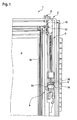
- FIG. 1 shows a portion of a residential roof window 1, which has a sash 2 with frame legs 3. Between the frame legs 3 and on the sash 2 a glazing 4 is provided. On the frame leg 3 is intended in FIG. 2 illustrated cover plate 5 are attached. For this purpose, a fastening device 6 is provided, which on the cover plate 5, a support member 7 and a rear handle member 8 and on the frame legs 3, a counter-support member 9 and a rear handle counter-element 10 provides.
- the rear grip element 8 is designed as a securing pin 11.
- a further support element 12 is provided on the cover plate 5
- a further counter-support element 13 is provided on the frame leg 3 in the region of the rear grip counter-element 10.
- the further counter-support element 13 is formed by the rear counter-counterpart element 10 with.
- the support element 7 with the counter-support element 9 and the further support member 12 with the other counter-support element 13 cooperate to hold the cover plate 5 axially immovable to the frame legs 3. At the same time a displacement of the cover plate 5 in the radial or lateral direction is prevented.
- the locking pin 11 is provided, which is slidably mounted with respect to the cover plate 5 and can be manually operated. In order to prevent the lifting, the locking pin 11 is actuated so that it is in its securing position.
- the attachment of the cover plate 5 on the frame member 3 is carried out as described below: First, the cover plate 5 is placed on the frame member 3, so that the support member 7 is disposed in the region of the counter-support member 9 and can be pushed onto this. Subsequently, the cover plate 5 is displaced in the axial direction until the counter-support element 9 or wing 14 of the counter-support element 9 engage in the support element 7. If the wings 14 are completely inserted into the support element 7, then the cover plate 5 bears against the frame limb 3. Subsequently, the locking pin 11 is actuated, that is displaced in its axial direction with respect to the cover plate 5, so that a rear grip connection of the locking pin 11 is made with the rear handle counter-element 10.
- the rear handle counter-element 10 may be formed for example U-shaped, so enclose the locking pin so at least partially.
- the cover plate 5 may be provided such that a bead 15 receives a projection 16 of the casement 2 in such a way to realize an additional guide of the cover plate 5 when pushed onto the frame leg 3.
- the engagement of the protrusion 16 in the bead 15 serves to achieve a good visual impression of the residential roof window.
- a further cover plate 17 is attached to the cover plate 5 by means of a mounting member 18.
- the mounting part 18 also has the locking pin 11 on or a bearing element 19, in which the locking pin 11 is guided displaceably.
- the locking pin 11 and the support member 7 are accordingly the cover plate 5 and the rear handle counter-element 10 and the counter-support member 9 and 13 associated with the frame leg 3.
- the support element 7 is designed as a drive-in pocket 20.
- An inner area of the entrance pocket 20 is bounded by a pocket wall 21. As in FIG. 2 it can be seen, this is at least partially formed by the cover plate 5.
- the support element 7 is arranged at a distance from the further support element 12 or the securing pin 11.
- the counter-support member 9 is spaced from the other counter-support member 13 and the rear handle counter-element 10.
- the support element 7 is fastened to the cover plate 5 by means of at least one rivet 22.
- mounting part 18 and the cover plate 5 and the further cover plate 17 is for example a snap-in connection. Again, however, may alternatively be provided a riveted connection.
- an additional cover plate can be attached by means of a further mounting part on the further cover plate 17, so that a U-shaped cover is present, which has on both sides via a locking pin 11, a support member 7 and another support member 12.
- the cover plate 5, the additional cover plate 17 and the additional cover plate are fastened together in the form of the cover member on the sash 2 and fixed by means of the fastening device 6.
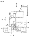
- FIG. 3 shows an enlarged view of the released mounting part 18. It can be seen that the locking pin 11 is arranged in the bearing element 19.
- the securing pin 11 has an actuating region 23, on which a fitter for displacing the securing pin 11 engages in its securing position.
- the FIG. 3 shows the locking pin 11 in its Abhebewolf. This means that in this position the cover plate 5 can be lifted off the frame leg 3. For shifting into the securing position, the securing pin 11 is moved in the direction of the arrow 24. In the FIG. 3 is indicated that the locking pin 11 via a Latch 25 has, which is part of a latching connection 26.
- the locking connection 26 represents a pull-out protection, thus preventing withdrawal of the locking pin 11 from the bearing element 19, starting from the position shown.
- the latching lug 25 or the latching connection 26 cooperates with a guide opening 27 of the bearing element 19.
- the guide opening 27 is penetrated by the locking pin 11, thus forms a storage for the locking pin 11 at least partially.
- the locking lug 25 cooperates with an edge 28 of the guide opening 27 to produce the latching connection between the locking pin 11 and the bearing element 19.
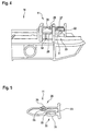
- FIG. 4 shows a portion of the mounting member 18 in a side view. It can be seen that the bearing element 19 has the guide opening 27 and a further guide opening 29. It is also clearly visible how the detent 25 cooperates with the edge 28 to prevent withdrawal of the locking pin 11 from the bearing element 19.
- the locking pin 11 has, in addition to the latching connection 26, a latching device 30. This has a latching projection 31, which is arranged on a spring bridge 32. The latching projection 31 prevents both unintentional introduction of the locking pin 11 in the bearing element 19, that is, a displacement of the locking pin 11 in its securing position. On the other hand, it prevents as soon as the locking pin 11 is in its securing position, a move out of this.
- the locking pin 11 can not be moved out of its secure position unintentionally.
- the spring bridge 31 is curved in the cross section of the locking pin 11 seen outwards, whereby a good spring action is achieved.
- the spring force of the spring bridge 32 urges the locking projection 31 of the locking pin 11 in its locking position, ie in a position in which both an accidental introduction and removal from the securing position is prevented.
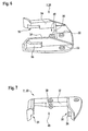
- FIG. 5 shows the release locking pin 11. Recognizable is the latching connection 26 and the latching device 30 and the actuating portion 23.
- the latching connection 26 has the locking lug 25, while the latching device 30 has the latching projection 31 on the spring bridge 32.
- the latching lug 25 of the latching connection 26 is located on a further spring bridge 33. However, this is small in comparison to the spring bridge 32, so that their spring action is low. This is due to the fact that the further spring bridge 33 is only required in order to allow the latching lug 25 to retract when the securing pin 11 is inserted into the bearing element 19. An application of the securing pin 11 from the bearing element 19 is usually not provided.
- FIG. 6 shows a view of the support element 7.
- This is designed as a entrance pocket 20.
- the support element 7 is fastened by means of rivets 22 to the cover plate 5.
- rear grip areas 35 are formed in lateral pocket walls 34, in which the wings 14 of the counter support element 9 can engage.
- the counter-support element is arranged in the mounting position of the cover plate 5 in the support element, wherein the wings 14 engage in the rear handle portions 35.
- the rear grip portions 35 can be opened or closed in the direction of the cover plate 5 either. In the former case, an area of the cover plate 5 forms a contact surface for the counter-support element 9 or its wings 14.
- a contact rail 36 is provided which limits the rear grip area 35 in the direction of the cover plate 5.
- a rear pocket wall 37 forms a contact surface for a front edge 38 of the counter-support element 9 (see FIG. 1 ). The leading edge 38 enters against the rear pocket wall 37 as soon as the cover plate 5 is in its mounting position. In this way, the axial support of the cover plate 5 is realized.
- a pin 39 is also provided, which fulfills the function of a blank holder 40.
- the pin 39 is bevelled in its front region, so that the counter-supporting element 9 runs on the pin 39 when it is pushed into the entry pocket 20.
- the counter-support element is thereby pushed away from the pin 39 of the cover plate 5.
- the counter-support member 9 is urged against an upper limit of the rear grip portions 35 and thus held firmly in this.
- the front edge 38 of the mating support member 9 abuts the rear pocket wall 37 and a portion of the mating support member 9 is based on the pin 39 from or rests on this, the wings 14 of the mating support member 9 against the upper limits of the rear grip areas 35 are urged.
- the wings 14 and the rear grip portions 35 and the locking pin 11 and the rear handle counter-element 10 thus form means 41st for radially non-displaceable support of the cover plate 5 on the frame legs. 5
- the locking pin 11 is equipped with a recognition feature which allows a fitter of the residential roof window 1 a clear recognition of the locking pin 11.
- the locking pin 11 is held in a signal color.
- signal color means that the color of colors of the surrounding components settles so far that a unambiguous identification is possible even in poor visibility.
- 23 transverse grooves are provided in the actuation region, which make it possible to feel the locking pin 11 and a secure operation.
Landscapes
- Engineering & Computer Science (AREA)
- General Engineering & Computer Science (AREA)
- Architecture (AREA)
- Civil Engineering (AREA)
- Structural Engineering (AREA)
- Mechanical Engineering (AREA)
- Operating, Guiding And Securing Of Roll- Type Closing Members (AREA)
- Roof Covering Using Slabs Or Stiff Sheets (AREA)
- Emergency Lowering Means (AREA)
Applications Claiming Priority (1)
| Application Number | Priority Date | Filing Date | Title |
|---|---|---|---|
| DE102009033939A DE102009033939B4 (de) | 2009-07-14 | 2009-07-14 | Wohndachfenster sowie Verfahren zum Befestigen eines Abdeckblechs |
Publications (3)
| Publication Number | Publication Date |
|---|---|
| EP2287416A2 true EP2287416A2 (fr) | 2011-02-23 |
| EP2287416A3 EP2287416A3 (fr) | 2015-06-17 |
| EP2287416B1 EP2287416B1 (fr) | 2016-10-12 |
Family
ID=42973844
Family Applications (1)
| Application Number | Title | Priority Date | Filing Date |
|---|---|---|---|
| EP10006079.7A Active EP2287416B1 (fr) | 2009-07-14 | 2010-06-11 | Fenêtre de toit avec un dispositif de fixation pour une tôle de recouvrement et méthode de fixation pour la tôle |
Country Status (3)
| Country | Link |
|---|---|
| EP (1) | EP2287416B1 (fr) |
| DE (1) | DE102009033939B4 (fr) |
| PL (1) | PL2287416T3 (fr) |
Cited By (2)
| Publication number | Priority date | Publication date | Assignee | Title |
|---|---|---|---|---|
| EP2947226A1 (fr) * | 2014-05-22 | 2015-11-25 | Roto Frank Ag | Fenêtre de toit d'habitation dotée d'une zinguerie destinée à recouvrir des zones extérieures d'un chambranle et d'un dormant |
| EP3045609A1 (fr) * | 2015-01-19 | 2016-07-20 | FAKRO PP Sp. z o.o. | Fenêtre de toit ou sas de toit à battant ouvrable vers l'extérieur avec mécanisme de fixation de l'élément de recouvrement supérieur |
Families Citing this family (1)
| Publication number | Priority date | Publication date | Assignee | Title |
|---|---|---|---|---|
| CN102140880B (zh) * | 2011-03-18 | 2012-09-26 | 湖南鑫美格新型装饰材料有限公司 | 门套防潮防腐用脚板及包含该脚板的门套 |
Family Cites Families (5)
| Publication number | Priority date | Publication date | Assignee | Title |
|---|---|---|---|---|
| DE9016725U1 (de) * | 1990-12-11 | 1991-03-28 | Roto Frank AG, 7022 Leinfelden-Echterdingen | Abdeckung für einen Flügelrahmen eines Dachfensters |
| DE10217532A1 (de) * | 2002-04-17 | 2003-11-13 | Roto Frank Ag | Dachfenster mit geklipster Abdeckung |
| EP1533440A3 (fr) * | 2003-11-21 | 2008-04-02 | VKR Holding A/S | Châssis d'étanchéité pour vantail d'une fenêtre de toiture et fenêtre de toiture avec un tel châssis |
| CN2714760Y (zh) * | 2003-11-21 | 2005-08-03 | Vkr控股公司 | 窗户顶罩板 |
| EP2242889B1 (fr) * | 2007-12-19 | 2015-10-21 | VKR Holding A/S | Protection contre les intempéries |
-
2009
- 2009-07-14 DE DE102009033939A patent/DE102009033939B4/de not_active Expired - Fee Related
-
2010
- 2010-06-11 EP EP10006079.7A patent/EP2287416B1/fr active Active
- 2010-06-11 PL PL10006079T patent/PL2287416T3/pl unknown
Non-Patent Citations (1)
| Title |
|---|
| None |
Cited By (2)
| Publication number | Priority date | Publication date | Assignee | Title |
|---|---|---|---|---|
| EP2947226A1 (fr) * | 2014-05-22 | 2015-11-25 | Roto Frank Ag | Fenêtre de toit d'habitation dotée d'une zinguerie destinée à recouvrir des zones extérieures d'un chambranle et d'un dormant |
| EP3045609A1 (fr) * | 2015-01-19 | 2016-07-20 | FAKRO PP Sp. z o.o. | Fenêtre de toit ou sas de toit à battant ouvrable vers l'extérieur avec mécanisme de fixation de l'élément de recouvrement supérieur |
Also Published As
| Publication number | Publication date |
|---|---|
| EP2287416A3 (fr) | 2015-06-17 |
| EP2287416B1 (fr) | 2016-10-12 |
| DE102009033939B4 (de) | 2011-07-21 |
| DE102009033939A1 (de) | 2011-02-10 |
| PL2287416T3 (pl) | 2017-03-31 |
Similar Documents
| Publication | Publication Date | Title |
|---|---|---|
| DE69705662T2 (de) | Rollvorrichtung für Schiebetüren, Fenster oder ähnliches | |
| EP2059148B1 (fr) | Tiroir | |
| EP3408484B1 (fr) | Module de levage de fenêtre muni d'un élément de guidage de vitre en plusieurs parties pour type de vitre à fleur de surface et procédé de montage | |
| EP3639334B1 (fr) | Fixation a un rail de support | |
| EP3773075A1 (fr) | Dispositif de fixation d'un élément de poussée et procédé de montage et de démontage d'un élément de poussée | |
| EP1857688A2 (fr) | Fixation par clipsage ou encliquetage permettant de fixer une paroi mince sur un support de paroi | |
| DE102011011113A1 (de) | Rahmensystem eines Partikelschutzgitters | |
| EP2287416B1 (fr) | Fenêtre de toit avec un dispositif de fixation pour une tôle de recouvrement et méthode de fixation pour la tôle | |
| DE102009033938B4 (de) | Wohndachfenster sowie Verfahren zum Befestigen eines Abdeckblechs | |
| DE102009018781B4 (de) | Verbindungsbaugruppe | |
| EP2947221B1 (fr) | Fenêtre de toit et procédé de montage d'une fenêtre de toit | |
| DE102013100922A1 (de) | Laufteil zum Führen eines Möbelteils in einer Führungsrichtung über eine Führungsschiene und Möbelbeschlag | |
| DE102009033941A1 (de) | Wohndachfenster mit einem Flügelrahmen | |
| EP2317047B1 (fr) | Agencement de ferrure | |
| DE102015219814A1 (de) | Wagenheberaufnahme für einen Kraftwagen und Verfahren zur Montage einer solchen Wagenheberaufnahme | |
| EP3860400B1 (fr) | Dispositif de fixation servant à fixer un panneau d'un tiroir sur un châssis | |
| EP3477029A1 (fr) | Ferrure de guidage pour un battant coulissant | |
| DE69205091T2 (de) | Aushebevorbeugungsvorrichtung für Schiebeflügel, insbesondere einer Tür, eines Fensters oder ähnlichem. | |
| EP3235984B1 (fr) | Ferrure de fenêtre, son procédé de fabrication et fenêtre correspondante | |
| DE202013100319U1 (de) | Profilelement | |
| DE102018100550A1 (de) | Führungsgleiter für ein schiebetür- und/oder schiebefenstersystem, beweglicher schieberahmen mit einem führungsgleiter sowie schiebetür- und/oder schiebefenstersystem mit führungsleiter | |
| DE102021125772B4 (de) | Abstandhalter, Führungsschiene für einen Raffstore oder eine Jalousie sowie Raffstore und Jalousie und Verfahren hierfür | |
| DE19857384C2 (de) | Befestigungsmittel zum Verbinden eines Flügelrahmens mit einem Blendrahmen zu einem nicht öffenbaren Fenster | |
| EP1200695B1 (fr) | Carter pour systeme de transmission | |
| DE202010004012U1 (de) | Befestigungselement für Stulpschienenbeschläge für Fenster und Türen |
Legal Events
| Date | Code | Title | Description |
|---|---|---|---|
| PUAI | Public reference made under article 153(3) epc to a published international application that has entered the european phase |
Free format text: ORIGINAL CODE: 0009012 |
|
| AK | Designated contracting states |
Kind code of ref document: A2 Designated state(s): AL AT BE BG CH CY CZ DE DK EE ES FI FR GB GR HR HU IE IS IT LI LT LU LV MC MK MT NL NO PL PT RO SE SI SK SM TR |
|
| AX | Request for extension of the european patent |
Extension state: BA ME RS |
|
| PUAL | Search report despatched |
Free format text: ORIGINAL CODE: 0009013 |
|
| AK | Designated contracting states |
Kind code of ref document: A3 Designated state(s): AL AT BE BG CH CY CZ DE DK EE ES FI FR GB GR HR HU IE IS IT LI LT LU LV MC MK MT NL NO PL PT RO SE SI SK SM TR |
|
| AX | Request for extension of the european patent |
Extension state: BA ME RS |
|
| RIC1 | Information provided on ipc code assigned before grant |
Ipc: E04D 13/03 20060101AFI20150508BHEP Ipc: E06B 1/34 20060101ALI20150508BHEP Ipc: F16B 41/00 20060101ALI20150508BHEP |
|
| 17P | Request for examination filed |
Effective date: 20151217 |
|
| RBV | Designated contracting states (corrected) |
Designated state(s): AL AT BE BG CH CY CZ DE DK EE ES FI FR GB GR HR HU IE IS IT LI LT LU LV MC MK MT NL NO PL PT RO SE SI SK SM TR |
|
| GRAP | Despatch of communication of intention to grant a patent |
Free format text: ORIGINAL CODE: EPIDOSNIGR1 |
|
| INTG | Intention to grant announced |
Effective date: 20160502 |
|
| GRAS | Grant fee paid |
Free format text: ORIGINAL CODE: EPIDOSNIGR3 |
|
| GRAA | (expected) grant |
Free format text: ORIGINAL CODE: 0009210 |
|
| AK | Designated contracting states |
Kind code of ref document: B1 Designated state(s): AL AT BE BG CH CY CZ DE DK EE ES FI FR GB GR HR HU IE IS IT LI LT LU LV MC MK MT NL NO PL PT RO SE SI SK SM TR |
|
| REG | Reference to a national code |
Ref country code: GB Ref legal event code: FG4D Free format text: NOT ENGLISH |
|
| REG | Reference to a national code |
Ref country code: CH Ref legal event code: EP |
|
| REG | Reference to a national code |
Ref country code: AT Ref legal event code: REF Ref document number: 836654 Country of ref document: AT Kind code of ref document: T Effective date: 20161015 |
|
| REG | Reference to a national code |
Ref country code: IE Ref legal event code: FG4D Free format text: LANGUAGE OF EP DOCUMENT: GERMAN |
|
| REG | Reference to a national code |
Ref country code: DE Ref legal event code: R096 Ref document number: 502010012528 Country of ref document: DE |
|
| REG | Reference to a national code |
Ref country code: CH Ref legal event code: NV Representative=s name: OFFICE ERNEST T. FREYLINGER S.A., CH |
|
| REG | Reference to a national code |
Ref country code: LT Ref legal event code: MG4D |
|
| REG | Reference to a national code |
Ref country code: NL Ref legal event code: MP Effective date: 20161012 |
|
| PG25 | Lapsed in a contracting state [announced via postgrant information from national office to epo] |
Ref country code: LV Free format text: LAPSE BECAUSE OF FAILURE TO SUBMIT A TRANSLATION OF THE DESCRIPTION OR TO PAY THE FEE WITHIN THE PRESCRIBED TIME-LIMIT Effective date: 20161012 |
|
| PG25 | Lapsed in a contracting state [announced via postgrant information from national office to epo] |
Ref country code: LT Free format text: LAPSE BECAUSE OF FAILURE TO SUBMIT A TRANSLATION OF THE DESCRIPTION OR TO PAY THE FEE WITHIN THE PRESCRIBED TIME-LIMIT Effective date: 20161012 Ref country code: NO Free format text: LAPSE BECAUSE OF FAILURE TO SUBMIT A TRANSLATION OF THE DESCRIPTION OR TO PAY THE FEE WITHIN THE PRESCRIBED TIME-LIMIT Effective date: 20170112 Ref country code: GR Free format text: LAPSE BECAUSE OF FAILURE TO SUBMIT A TRANSLATION OF THE DESCRIPTION OR TO PAY THE FEE WITHIN THE PRESCRIBED TIME-LIMIT Effective date: 20170113 Ref country code: SE Free format text: LAPSE BECAUSE OF FAILURE TO SUBMIT A TRANSLATION OF THE DESCRIPTION OR TO PAY THE FEE WITHIN THE PRESCRIBED TIME-LIMIT Effective date: 20161012 |
|
| PG25 | Lapsed in a contracting state [announced via postgrant information from national office to epo] |
Ref country code: NL Free format text: LAPSE BECAUSE OF FAILURE TO SUBMIT A TRANSLATION OF THE DESCRIPTION OR TO PAY THE FEE WITHIN THE PRESCRIBED TIME-LIMIT Effective date: 20161012 Ref country code: ES Free format text: LAPSE BECAUSE OF FAILURE TO SUBMIT A TRANSLATION OF THE DESCRIPTION OR TO PAY THE FEE WITHIN THE PRESCRIBED TIME-LIMIT Effective date: 20161012 Ref country code: IS Free format text: LAPSE BECAUSE OF FAILURE TO SUBMIT A TRANSLATION OF THE DESCRIPTION OR TO PAY THE FEE WITHIN THE PRESCRIBED TIME-LIMIT Effective date: 20170212 Ref country code: FI Free format text: LAPSE BECAUSE OF FAILURE TO SUBMIT A TRANSLATION OF THE DESCRIPTION OR TO PAY THE FEE WITHIN THE PRESCRIBED TIME-LIMIT Effective date: 20161012 Ref country code: PT Free format text: LAPSE BECAUSE OF FAILURE TO SUBMIT A TRANSLATION OF THE DESCRIPTION OR TO PAY THE FEE WITHIN THE PRESCRIBED TIME-LIMIT Effective date: 20170213 Ref country code: HR Free format text: LAPSE BECAUSE OF FAILURE TO SUBMIT A TRANSLATION OF THE DESCRIPTION OR TO PAY THE FEE WITHIN THE PRESCRIBED TIME-LIMIT Effective date: 20161012 |
|
| REG | Reference to a national code |
Ref country code: FR Ref legal event code: PLFP Year of fee payment: 8 |
|
| REG | Reference to a national code |
Ref country code: DE Ref legal event code: R097 Ref document number: 502010012528 Country of ref document: DE |
|
| PG25 | Lapsed in a contracting state [announced via postgrant information from national office to epo] |
Ref country code: EE Free format text: LAPSE BECAUSE OF FAILURE TO SUBMIT A TRANSLATION OF THE DESCRIPTION OR TO PAY THE FEE WITHIN THE PRESCRIBED TIME-LIMIT Effective date: 20161012 Ref country code: DK Free format text: LAPSE BECAUSE OF FAILURE TO SUBMIT A TRANSLATION OF THE DESCRIPTION OR TO PAY THE FEE WITHIN THE PRESCRIBED TIME-LIMIT Effective date: 20161012 Ref country code: SK Free format text: LAPSE BECAUSE OF FAILURE TO SUBMIT A TRANSLATION OF THE DESCRIPTION OR TO PAY THE FEE WITHIN THE PRESCRIBED TIME-LIMIT Effective date: 20161012 Ref country code: RO Free format text: LAPSE BECAUSE OF FAILURE TO SUBMIT A TRANSLATION OF THE DESCRIPTION OR TO PAY THE FEE WITHIN THE PRESCRIBED TIME-LIMIT Effective date: 20161012 |
|
| PLBE | No opposition filed within time limit |
Free format text: ORIGINAL CODE: 0009261 |
|
| STAA | Information on the status of an ep patent application or granted ep patent |
Free format text: STATUS: NO OPPOSITION FILED WITHIN TIME LIMIT |
|
| PG25 | Lapsed in a contracting state [announced via postgrant information from national office to epo] |
Ref country code: SM Free format text: LAPSE BECAUSE OF FAILURE TO SUBMIT A TRANSLATION OF THE DESCRIPTION OR TO PAY THE FEE WITHIN THE PRESCRIBED TIME-LIMIT Effective date: 20161012 Ref country code: BG Free format text: LAPSE BECAUSE OF FAILURE TO SUBMIT A TRANSLATION OF THE DESCRIPTION OR TO PAY THE FEE WITHIN THE PRESCRIBED TIME-LIMIT Effective date: 20170112 |
|
| PGFP | Annual fee paid to national office [announced via postgrant information from national office to epo] |
Ref country code: IT Payment date: 20170622 Year of fee payment: 8 |
|
| 26N | No opposition filed |
Effective date: 20170713 |
|
| PG25 | Lapsed in a contracting state [announced via postgrant information from national office to epo] |
Ref country code: SI Free format text: LAPSE BECAUSE OF FAILURE TO SUBMIT A TRANSLATION OF THE DESCRIPTION OR TO PAY THE FEE WITHIN THE PRESCRIBED TIME-LIMIT Effective date: 20161012 |
|
| PG25 | Lapsed in a contracting state [announced via postgrant information from national office to epo] |
Ref country code: MC Free format text: LAPSE BECAUSE OF FAILURE TO SUBMIT A TRANSLATION OF THE DESCRIPTION OR TO PAY THE FEE WITHIN THE PRESCRIBED TIME-LIMIT Effective date: 20161012 |
|
| REG | Reference to a national code |
Ref country code: IE Ref legal event code: MM4A |
|
| PG25 | Lapsed in a contracting state [announced via postgrant information from national office to epo] |
Ref country code: IE Free format text: LAPSE BECAUSE OF NON-PAYMENT OF DUE FEES Effective date: 20170611 Ref country code: LU Free format text: LAPSE BECAUSE OF NON-PAYMENT OF DUE FEES Effective date: 20170611 |
|
| REG | Reference to a national code |
Ref country code: BE Ref legal event code: MM Effective date: 20170630 |
|
| REG | Reference to a national code |
Ref country code: FR Ref legal event code: PLFP Year of fee payment: 9 |
|
| PGFP | Annual fee paid to national office [announced via postgrant information from national office to epo] |
Ref country code: CZ Payment date: 20180531 Year of fee payment: 9 Ref country code: CH Payment date: 20180626 Year of fee payment: 9 |
|
| PG25 | Lapsed in a contracting state [announced via postgrant information from national office to epo] |
Ref country code: BE Free format text: LAPSE BECAUSE OF NON-PAYMENT OF DUE FEES Effective date: 20170630 |
|
| PGFP | Annual fee paid to national office [announced via postgrant information from national office to epo] |
Ref country code: AT Payment date: 20180620 Year of fee payment: 9 Ref country code: PL Payment date: 20180608 Year of fee payment: 9 Ref country code: FR Payment date: 20180625 Year of fee payment: 9 |
|
| PG25 | Lapsed in a contracting state [announced via postgrant information from national office to epo] |
Ref country code: MT Free format text: LAPSE BECAUSE OF FAILURE TO SUBMIT A TRANSLATION OF THE DESCRIPTION OR TO PAY THE FEE WITHIN THE PRESCRIBED TIME-LIMIT Effective date: 20161012 |
|
| PGFP | Annual fee paid to national office [announced via postgrant information from national office to epo] |
Ref country code: GB Payment date: 20180626 Year of fee payment: 9 |
|
| PG25 | Lapsed in a contracting state [announced via postgrant information from national office to epo] |
Ref country code: IT Free format text: LAPSE BECAUSE OF NON-PAYMENT OF DUE FEES Effective date: 20180611 |
|
| PG25 | Lapsed in a contracting state [announced via postgrant information from national office to epo] |
Ref country code: HU Free format text: LAPSE BECAUSE OF FAILURE TO SUBMIT A TRANSLATION OF THE DESCRIPTION OR TO PAY THE FEE WITHIN THE PRESCRIBED TIME-LIMIT; INVALID AB INITIO Effective date: 20100611 |
|
| PG25 | Lapsed in a contracting state [announced via postgrant information from national office to epo] |
Ref country code: CY Free format text: LAPSE BECAUSE OF NON-PAYMENT OF DUE FEES Effective date: 20161012 |
|
| PG25 | Lapsed in a contracting state [announced via postgrant information from national office to epo] |
Ref country code: MK Free format text: LAPSE BECAUSE OF FAILURE TO SUBMIT A TRANSLATION OF THE DESCRIPTION OR TO PAY THE FEE WITHIN THE PRESCRIBED TIME-LIMIT Effective date: 20161012 |
|
| PG25 | Lapsed in a contracting state [announced via postgrant information from national office to epo] |
Ref country code: CZ Free format text: LAPSE BECAUSE OF NON-PAYMENT OF DUE FEES Effective date: 20190611 |
|
| REG | Reference to a national code |
Ref country code: CH Ref legal event code: PL |
|
| REG | Reference to a national code |
Ref country code: AT Ref legal event code: MM01 Ref document number: 836654 Country of ref document: AT Kind code of ref document: T Effective date: 20190611 |
|
| GBPC | Gb: european patent ceased through non-payment of renewal fee |
Effective date: 20190611 |
|
| PG25 | Lapsed in a contracting state [announced via postgrant information from national office to epo] |
Ref country code: TR Free format text: LAPSE BECAUSE OF FAILURE TO SUBMIT A TRANSLATION OF THE DESCRIPTION OR TO PAY THE FEE WITHIN THE PRESCRIBED TIME-LIMIT Effective date: 20161012 |
|
| PG25 | Lapsed in a contracting state [announced via postgrant information from national office to epo] |
Ref country code: AT Free format text: LAPSE BECAUSE OF NON-PAYMENT OF DUE FEES Effective date: 20190611 Ref country code: GB Free format text: LAPSE BECAUSE OF NON-PAYMENT OF DUE FEES Effective date: 20190611 |
|
| PG25 | Lapsed in a contracting state [announced via postgrant information from national office to epo] |
Ref country code: LI Free format text: LAPSE BECAUSE OF NON-PAYMENT OF DUE FEES Effective date: 20190630 Ref country code: CH Free format text: LAPSE BECAUSE OF NON-PAYMENT OF DUE FEES Effective date: 20190630 |
|
| PG25 | Lapsed in a contracting state [announced via postgrant information from national office to epo] |
Ref country code: FR Free format text: LAPSE BECAUSE OF NON-PAYMENT OF DUE FEES Effective date: 20190630 |
|
| PG25 | Lapsed in a contracting state [announced via postgrant information from national office to epo] |
Ref country code: AL Free format text: LAPSE BECAUSE OF FAILURE TO SUBMIT A TRANSLATION OF THE DESCRIPTION OR TO PAY THE FEE WITHIN THE PRESCRIBED TIME-LIMIT Effective date: 20161012 |
|
| PG25 | Lapsed in a contracting state [announced via postgrant information from national office to epo] |
Ref country code: PL Free format text: LAPSE BECAUSE OF NON-PAYMENT OF DUE FEES Effective date: 20190611 |
|
| PGFP | Annual fee paid to national office [announced via postgrant information from national office to epo] |
Ref country code: DE Payment date: 20250618 Year of fee payment: 16 |