EP2292844B2 - Corps de coupe pour la production d'un marquage de bande directrice et marquage de bande directrice - Google Patents
Corps de coupe pour la production d'un marquage de bande directrice et marquage de bande directrice Download PDFInfo
- Publication number
- EP2292844B2 EP2292844B2 EP10164541.4A EP10164541A EP2292844B2 EP 2292844 B2 EP2292844 B2 EP 2292844B2 EP 10164541 A EP10164541 A EP 10164541A EP 2292844 B2 EP2292844 B2 EP 2292844B2
- Authority
- EP
- European Patent Office
- Prior art keywords
- cutting
- convex
- road
- curve
- concave
- Prior art date
- Legal status (The legal status is an assumption and is not a legal conclusion. Google has not performed a legal analysis and makes no representation as to the accuracy of the status listed.)
- Active
Links
Images


Classifications
-
- E—FIXED CONSTRUCTIONS
- E01—CONSTRUCTION OF ROADS, RAILWAYS, OR BRIDGES
- E01C—CONSTRUCTION OF, OR SURFACES FOR, ROADS, SPORTS GROUNDS, OR THE LIKE; MACHINES OR AUXILIARY TOOLS FOR CONSTRUCTION OR REPAIR
- E01C23/00—Auxiliary devices or arrangements for constructing, repairing, reconditioning, or taking-up road or like surfaces
- E01C23/06—Devices or arrangements for working the finished surface; Devices for repairing or reconditioning the surface of damaged paving; Recycling in place or on the road
- E01C23/09—Devices or arrangements for working the finished surface; Devices for repairing or reconditioning the surface of damaged paving; Recycling in place or on the road for forming cuts, grooves, or recesses, e.g. for making joints or channels for markings, for cutting-out sections to be removed; for cleaning, treating, or filling cuts, grooves, recesses, or fissures; for trimming paving edges
- E01C23/0993—Devices or arrangements for working the finished surface; Devices for repairing or reconditioning the surface of damaged paving; Recycling in place or on the road for forming cuts, grooves, or recesses, e.g. for making joints or channels for markings, for cutting-out sections to be removed; for cleaning, treating, or filling cuts, grooves, recesses, or fissures; for trimming paving edges for forming or installing surface markings or signals in the paving, e.g. grooving for striping or for producing rumble strips, forming marker-receiving recesses
-
- E—FIXED CONSTRUCTIONS
- E01—CONSTRUCTION OF ROADS, RAILWAYS, OR BRIDGES
- E01F—ADDITIONAL WORK, SUCH AS EQUIPPING ROADS OR THE CONSTRUCTION OF PLATFORMS, HELICOPTER LANDING STAGES, SIGNS, SNOW FENCES, OR THE LIKE
- E01F9/00—Arrangement of road signs or traffic signals; Arrangements for enforcing caution
- E01F9/50—Road surface markings; Kerbs or road edgings, specially adapted for alerting road users
- E01F9/529—Road surface markings; Kerbs or road edgings, specially adapted for alerting road users specially adapted for signalling by sound or vibrations, e.g. rumble strips; specially adapted for enforcing reduced speed, e.g. speed bumps
Definitions
- the invention relates to a cutting body for generating a road marking with a rotating body rotatable about an axis of rotation, which can interchangeably accommodate a plurality of cutting elements which define a cutting curve.
- a road milling machine with a cutting body which has a milling drum tube as a rotating body.
- the roller surface is barrel-shaped and convex in the direction of the axis of rotation. It holds chisel holders in which chisels can be exchangeably held.
- the chisels are equipped with carbide tips that serve as cutting elements.
- the carbide tips form a convex cutting curve in the direction of the axis of rotation of the milling drum tube. This convex cutting curve results during the rotation of the rotating body.
- a concave trough is produced transversely to the longitudinal extent of the roadway. Due to the circular cross-section of the rotating body, the depression has a concave shape even in the longitudinal direction.
- a plurality of depressions are milled into the lane at an equal spacing from one another. The road marking thus forms a deliberate geometric unevenness in the road. When rolling over with a vehicle tire, noises and vibrations occur which are perceived by the driver and which signal him to leave the road, for example.
- the road markings thus have the function and task of emitting an acoustic and haptic warning signal.
- this noise source is sometimes perceived as disturbing by the surrounding area adjacent to the road.
- Another disadvantage of the known road markings arises when driving over with a two-wheeler. The two-wheeler is moved laterally, which can then trigger dangerous steering corrections for the driver. If rainwater collects in the depressions, the driving situation of the two-wheeler can also become unstable.
- a cutting body for producing a road marking is known.
- a rotary body which has a large number of cutting elements.
- the cutting elements are formed by diamond particles that are attached to a contoured surface of the rotating body.
- the rotating body forms a cutting curve with the cutting elements.
- the cutting curve is formed by four convex elevations and three concave transition sections.
- the concave transition sections merge into these between the convex elevations.
- This known cutting body can be set in rotation during the use of the tool and placed on the road surface to be machined.
- the cutting bodies grind themselves into the road surface.
- Line-shaped depressions can thus be introduced into the roadway. These line-shaped depressions serve to receive color, so that, for example, road side markings can be generated. Due to the grinding technology used, the indentations in the road surface can only be created with a low penetration depth.
- Cutting bodies with which road markings can be milled into the road surface are also known from the prior art.
- the US 2004/0005190 A1 shows such an arrangement.
- Interchangeable cutting teeth are mounted on a cylindrical cutting roller.
- the cutting teeth are positioned with respect to one another in a predetermined arrangement.
- the cutting roller can be rotated.
- the roller rotating device is assigned a lifting device which periodically raises and lowers the cutting roller.
- the lifting and lowering movement is superimposed on a linear movement of the construction vehicle along the direction of the road. This creates a cutting movement, with each cutting tooth lifting a comma-shaped chip out of the road surface.
- This essentially results in part-circular recesses in the road surface. Such recesses are unsuitable for use as vibrating strips.
- Vibrating strips form deliberate geometric bumps in the road.
- noises and vibrations occur which are perceived by the driver and which signal him to leave the road, for example.
- the road markings according to the D2 result in sharp-edged transitions between the road surface and the road marking. These jagged transitions move a two-wheeler sideways when driving over it, which can then trigger dangerous steering corrections for the driver.
- a relatively large amount of water collects in the depressions, which further unstabilizes the driving situation of the two-wheeler. It has also proven to be disadvantageous that there is a relatively high level of noise when driving over, which is sometimes perceived as annoying in the area adjacent to the road.
- the cutting curve forms a concave cutting area in the direction of the axis of rotation, and that a concave cutting area connects to the convex cutting area on both sides.
- depressions for road markings can be milled, in which the road surface is continuously transferred over the convex area into the concave floor.
- the geometry of the lane markings also enables a two-wheeler to drive over it more easily and to reduce side distortion that unsettles the driver.
- the volume formed by the depression is reduced with the convex region of the depression. This means that less water can collect in it, which significantly reduces the risk of instability of a two-wheeler on wet roads.
- the rotary body has a fastening surface on which tool holders are fastened, which can receive the cutting elements interchangeably, that the fastening surface has a convex fastening section assigned to the convex cutting region and one has the concave cutting portion associated concave attachment portion.
- the cutting curve can be generated in a simple manner using the same bit holder and cutting elements.
- the concave cutting areas ends at the end facing away from the convex cutting area in an end area parallel to the axis of rotation. In this way, a harmonious transition to the road surface is created in the recess, which withstands particularly robust mechanical loads.
- the radius of the convex cutting area is between 200 mm and 400 mm, and / or that the radius of the concave cutting area is between 400 mm and 800 mm, then corresponding geometries result at the depression, which have a reduced influence on the Sufficient noise can be generated by the tire guide.
- a cutting body according to the invention can be characterized in that a fastening flange is arranged in the hollow area enclosed by the rotating body and that the fastening flange is coupled to the rotating body on the inner wall section assigned to the convex cutting area.
- the fastening flange is thus fixed in the thickened section of the rotary body formed by the convex cutting area in a manner optimized for strength.
- road markings can be produced in the form of depressions, the depressions having two lateral longitudinal walls running in the longitudinal direction of the road, which merge into a floor area, the depressions being delimited by two transverse walls running transverse to the direction of the road, with a convex area at least one of the longitudinal walls in a concave area of the floor is transferred and / or wherein the convex area of at least one of the side walls is transferred into the road surface.
- depressions are created that have little impact on the lateral guidance of the wheel.
- the transverse walls can have a concave region which is passed directly or indirectly into the road surface. Then a sufficiently high sound pressure is created when the wheel hits the transverse wall.
- the depressions can be spaced apart from one another in the same division grid to form the road marking, or it is conceivable that the individual depressions directly adjoin one another.
- Figure 1 shows a cutting body having a roller-shaped rotating body 10.
- the rotary body 10 is tubular and has a cylindrical inner receptacle, which is formed by the jacket of the rotary body 10.
- a fastening flange 11 with fastening receptacles 12 is arranged in the inner receptacle, to which the output shaft of a drive train can be flanged.
- the jacket of the rotary body 10 forms a support part 13 with a barrel-shaped circumferential fastening surface 14.
- the fastening surface 14 is composed of a central convex fastening section 14.2 and two concave fastening sections 14.1 adjoining it laterally.
- the concave fastening sections 14.1 merge directly into the convex fastening section 14.2.
- On the two mounting sections 14.1 and 14.2 are tool holder changing systems, consisting of a base part and a tool holder 20 which can be exchangeably fastened to it.
- the base parts are welded to the fastening sections 14.1, 14.2.
- the base parts are arranged offset to one another in the circumferential direction, so that there are clearing and loading turns that run spirally on the fastening sections 14.1, 14.2.
- the chisel holders 20 are welded directly onto the fastening sections 14.1, 14.2, so that base parts can be dispensed with.
- the chisel holders 20 have chisel holders in which chisels 21, preferably round-shank chisels, can be exchangeably received.
- the chisels 21 are equipped with cutting elements which, when the rotary body 10 rotates about the axis of rotation R, define a cutting curve 15.
- the cutting curve 15 forms a kind of envelope.
- the cutting curve 15 forms a convex cutting area 15.2 and laterally adjoining concave cutting areas 15.1 corresponding to the configuration of the fastening sections 14.1, 14.2.
- the radius R 1 of the concave cutting areas 15.1 is preferably between 400 mm and 800 mm.
- the particularly preferred ratio R 1 : R 2 of approximately 2: 1 can be set.
- the cutting body can be used to mill road markings, consisting of depressions 31 arranged in a row one behind the other, into the roadway 30.
- the recess 31 has a concave bottom 31.2 complementary to the cutting curve 15 transversely to the longitudinal direction of the roadway, of which two convex longitudinal walls 31.1 rising up.
- the longitudinal walls 31.1 merge into the road surface 32.
- the transverse walls 31.3 running transversely to the longitudinal extent of the roadway are concavely curved in accordance with the circumference of the roller.
- Figure 3 shows an embodiment variant in which the cutting body is fed perpendicular to the road surface 32 and after the cutting body has reached its deepest infeed position is reset again before it is offset by the desired division in the longitudinal direction of the road, etc.
- Figure 4 shows one too Figure 3 changed procedure.
- the cutting body is not reset above the level of the road surface 32, but is continuously advanced to the lowest infeed position during the feed movement along the longitudinal direction of the road and is returned to the level of the road surface, so that the depressions 31 are lined up directly.
- the feed and reset movement can be coordinated with the feed movement in such a way that an alternating arrangement of convex and concave curved regions of the depression is likewise produced in the longitudinal direction of the carriageway. It can thereby be achieved that each individual depression of the series of depressions in the longitudinal section receives a curve shape similar to that of the cross section.
- Figure 5a shows a cutting body 10 according to the prior art, which generates a cylindrical envelope with its chisels 21.
- 10 road markings 31 with a partially cylindrical geometry can be milled with this cutting body, such as Figure 5b shows. That the Figure 5b removed enlarged detail acc.
- Figure 5c shows that this road markings 31 rugged 90 ° transition between the road surface 32 and the subsequent longitudinal wall 31.1 results.
- Figure 6a shows a further cutting body 10 according to the prior art (for example according to FIG US 6,547,484 B2 ).
- the chisels 21 produce a spherical cutting curve.
- This cutting body results in 10 road markings 31 of the in Figure 6b shown form.
- Figure 6c shows one of the Figure 6b extracted detail. It can be seen here that the transition from the road surface 32 into the longitudinal side walls 31.1 compared to the variant of FIG Figures 5b and 5c is clearly flattened, but still forms a relatively steep transition.
- Figure 7a shows the cutting body 10 according to improved comparison.
- Figure 1 shows the cutting body 10 according to improved comparison.
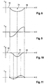
- Figure 7b circa Figure 2 and Figure 7c shows that the Figure 7b Enlarged detail marked with Vllc. It can clearly be seen that, according to the invention, an improved transition between the road surface 32 and the longitudinal wall 31.1 can be designed. This advantage is demonstrated by the Figures 8 to 11 further clarified.
- Figure 8 is the result of the cross-section.
- Figure 6b resulting contour of the road marking 31 is drawn as a curve in a coordinate system.
- Figure 10 shows analogously the curve of the lane marking acc. Figure 7b .
Landscapes
- Engineering & Computer Science (AREA)
- Architecture (AREA)
- Civil Engineering (AREA)
- Structural Engineering (AREA)
- Mining & Mineral Resources (AREA)
- Road Repair (AREA)
- Road Signs Or Road Markings (AREA)
Claims (7)
- Corps de coupe pour la production d'un marquage routier comprenant un corps rotatif (10) pouvant tourner autour d'un axe de rotation (R) qui peut recevoir de manière remplaçable une pluralité d'éléments de coupe (21) qui définissent une courbe de coupe (15)
dans lequel le corps rotatif (10) présente une surface de fixation (14) sur laquelle sont fixés de porte-outils (20) qui peuvent recevoir de manière remplaçable les éléments de coupe (21),
dans lequel la courbe de coupe (15) forme dans la direction de l'axe de rotation (R) une région de coupe convexe (15.2),
dans lequel la surface de fixation (14) présente une portion de fixation convexe (14.2) associée à la région de coupe convexe (15.2)
caractérisé en ce qu'une région de coupe concave (15.1) se raccorde à chaque fois de chaque côté à la région de coupe convexe (15.2),
en ce que la surface de fixation (14) présente une portion de fixation concave (14.1) associée à la région de coupe concave (15.1). - Corps de coupe selon la revendication 1,
caractérisé en ce que
la courbe de coupe (15) présente au niveau de l'extrémité opposée à la région de coupe convexe (15.2) et par rapport à l'axe de rotation une pente qui tend vers zéro ou qui présente à cet endroit une allure essentiellement parallèle à l'axe. - Corps de coupe selon la revendication 1 ou 2,
caractérisé en ce que
la courbe de coupe ou les régions individuelles de la courbe de coupe suivent une fonction réelle, en particulier une fonction trigonométrique. - Corps de coupe selon l'une quelconque des revendications 1 à 3,
caractérisé en ce que
le rayon (R2) de la région de coupe convexe (15.2) est compris entre 200 mm et 400 mm. - Corps de coupe selon l'une quelconque des revendications 1 à 4,
caractérisé en ce que
le rayon (R1) de la région de coupe concave (15.1) est compris entre 400 mm et 800 mm. - Corps de coupe selon l'une quelconque des revendications 1 à 5,
caractérisé en ce que
le corps rotatif (10) est réalisé en forme de rouleau. - Corps de coupe selon l'une quelconque des revendications 1 à 6,
caractérisé en ce
qu'une bride de fixation (11) est disposée dans la région creuse entourée par le corps rotatif (10) et
en ce que la bride de fixation (11) est raccordée au. corps rotatif (10) dans la portion de paroi interne associée à la région de coupe convexe (15.2).
Applications Claiming Priority (1)
| Application Number | Priority Date | Filing Date | Title |
|---|---|---|---|
| DE102009034766.6A DE102009034766B4 (de) | 2009-07-25 | 2009-07-25 | Schneidkörper zur Erzeugung einer Fahrbahnmarkierung und Fahrbahnmarkierung |
Publications (4)
| Publication Number | Publication Date |
|---|---|
| EP2292844A2 EP2292844A2 (fr) | 2011-03-09 |
| EP2292844A3 EP2292844A3 (fr) | 2012-03-28 |
| EP2292844B1 EP2292844B1 (fr) | 2014-06-11 |
| EP2292844B2 true EP2292844B2 (fr) | 2020-07-29 |
Family
ID=43038066
Family Applications (1)
| Application Number | Title | Priority Date | Filing Date |
|---|---|---|---|
| EP10164541.4A Active EP2292844B2 (fr) | 2009-07-25 | 2010-06-01 | Corps de coupe pour la production d'un marquage de bande directrice et marquage de bande directrice |
Country Status (6)
| Country | Link |
|---|---|
| US (1) | US8491219B2 (fr) |
| EP (1) | EP2292844B2 (fr) |
| JP (1) | JP5049373B2 (fr) |
| CN (2) | CN201908249U (fr) |
| CA (1) | CA2707289C (fr) |
| DE (1) | DE102009034766B4 (fr) |
Cited By (1)
| Publication number | Priority date | Publication date | Assignee | Title |
|---|---|---|---|---|
| RU2799220C1 (ru) * | 2022-10-20 | 2023-07-04 | Федеральное государственное бюджетное образовательное учреждение высшего образования "Казанский государственный архитектурно-строительный университет" (КазГАСУ) | Способ нанесения шумовой полосы |
Families Citing this family (13)
| Publication number | Priority date | Publication date | Assignee | Title |
|---|---|---|---|---|
| DE102011109450A1 (de) * | 2011-08-04 | 2013-02-07 | Bomag Gmbh | Fräsrotor zur Bearbeitung von Bodenmaterial sowie Bodenbearbeitungsmaschine mit einem derartigen Rotor |
| CN103194948A (zh) * | 2013-03-28 | 2013-07-10 | 郭子也 | 一种具有耐久节能交通安全线的路面及其铺设方法 |
| DE102014015584B4 (de) * | 2014-10-21 | 2018-10-25 | Bomag Gmbh | Fräswalze und Bodenfräsmaschine mit derartiger Fräswalze |
| CN105335546B (zh) * | 2015-09-08 | 2019-04-23 | 陕西高速机械化工程有限公司 | 一种路面养护的铣刨测量方法 |
| US20170211245A1 (en) | 2016-01-21 | 2017-07-27 | Diamond Surface, Inc. | Reduced volume sonic noise alert pattern grinder & method |
| CA3044842A1 (fr) * | 2016-11-23 | 2018-05-31 | Garlon J. Maxwell | Tambour de lissage a nivellement de precision pour le lissage de surfaces de revetement |
| US10352006B2 (en) | 2017-03-23 | 2019-07-16 | Waterblasting, Llc | Rumble strip forming apparatus and method |
| CN110924279B (zh) * | 2019-12-19 | 2020-12-22 | 利辛县灵犀工业设计有限公司 | 一种自动路面刨铣装置 |
| US20220151166A1 (en) * | 2020-11-13 | 2022-05-19 | 106 Reforestation, Llc | Roller for use with heavy equipment |
| EP4251802A4 (fr) * | 2020-11-24 | 2024-10-30 | Corning Research & Development Corporation | Outil de broyage à contrôle arrière doté de guides alignés horizontalement et tambour de broyage |
| CN112554014A (zh) * | 2020-11-27 | 2021-03-26 | 于江波 | 一种水泥道路施工用线形切割机构运动支架 |
| CN115573231B (zh) * | 2022-09-03 | 2024-04-26 | 邯郸市华威公路设计咨询有限公司 | 一种公路工程施工中道路标线磨除设备 |
| CN117988199B (zh) * | 2024-04-01 | 2024-09-03 | 智博建筑设计集团有限公司 | 一种市政园林施工标线清除装置及方法 |
Citations (4)
| Publication number | Priority date | Publication date | Assignee | Title |
|---|---|---|---|---|
| US5582490A (en) † | 1994-09-22 | 1996-12-10 | Wirtgen America, Inc. | Rumble strip cutter wheel |
| DE10007253A1 (de) † | 2000-02-17 | 2001-08-23 | Manfred Blessing | Fräswalze und Fräsmaschine mit Fräswalze |
| US20050077776A1 (en) † | 2003-08-26 | 2005-04-14 | Terry Hansen | Reinforced concrete milling/cutting mandrel |
| US7029072B1 (en) † | 2002-03-11 | 2006-04-18 | Wirtgen America, Inc. | Modified rumble strip cutter |
Family Cites Families (15)
| Publication number | Priority date | Publication date | Assignee | Title |
|---|---|---|---|---|
| US1529797A (en) * | 1921-10-26 | 1925-03-17 | William D Gray | Land roller |
| US3516712A (en) * | 1968-08-19 | 1970-06-23 | Jeffrey Galion Inc | Mining machine for mining material from the entire face |
| US3554606A (en) | 1969-01-22 | 1971-01-12 | Christensen Diamond Prod Co | Cutters for forming highway paint receiving grooves |
| US3774969A (en) * | 1971-12-22 | 1973-11-27 | Nat Mine Service Co | Continuous mining machine |
| US4310199A (en) * | 1979-09-20 | 1982-01-12 | National Mine Service Company | Cutter drum assembly for a continuous mining machine |
| US4999952A (en) * | 1989-06-09 | 1991-03-19 | Union Broach | Method and apparatus for manufacturing K-files and reamers |
| US5676490A (en) * | 1996-04-08 | 1997-10-14 | Nelson; Dale J. | Machine for cutting highway rumble strips |
| JPH1129905A (ja) * | 1997-06-06 | 1999-02-02 | Nippon Hodo Co Ltd | 注意喚起舗装の構築方法 |
| US6547484B2 (en) | 2001-02-14 | 2003-04-15 | Dustrol, Inc. | Apparatus for cutting rumble strips in a road surface |
| US20040005190A1 (en) * | 2002-07-08 | 2004-01-08 | Gerhard Jakits | Device and method for selectively milling the surface of a roadway |
| DE10245394C1 (de) * | 2002-09-28 | 2003-12-04 | Man Takraf Foerdertechnik Gmbh | Schrämförderwalze für ein kontinuierliches Tagebaugewinnungsgerät |
| US7029370B2 (en) * | 2003-02-24 | 2006-04-18 | Coneqtec Corp. | Grinding machines for depression patterns along roads |
| CN2858746Y (zh) * | 2005-11-30 | 2007-01-17 | 天津鼎盛工程机械有限公司 | 一种双向螺旋铣刨装置 |
| JP4018128B1 (ja) * | 2007-02-27 | 2007-12-05 | 正司建設株式会社 | 舗装路面溝切削装置 |
| CN101275383A (zh) * | 2007-03-30 | 2008-10-01 | 上海宝冶建设有限公司 | 道面伸缩缝切割、倒角装置及其使用方法 |
-
2009
- 2009-07-25 DE DE102009034766.6A patent/DE102009034766B4/de active Active
-
2010
- 2010-06-01 EP EP10164541.4A patent/EP2292844B2/fr active Active
- 2010-06-11 CA CA2707289A patent/CA2707289C/fr not_active Expired - Fee Related
- 2010-06-23 CN CN2010202343234U patent/CN201908249U/zh not_active Expired - Lifetime
- 2010-06-23 CN CN2010102071200A patent/CN101962931A/zh active Pending
- 2010-06-28 US US12/824,790 patent/US8491219B2/en active Active
- 2010-07-26 JP JP2010167082A patent/JP5049373B2/ja not_active Expired - Fee Related
Patent Citations (4)
| Publication number | Priority date | Publication date | Assignee | Title |
|---|---|---|---|---|
| US5582490A (en) † | 1994-09-22 | 1996-12-10 | Wirtgen America, Inc. | Rumble strip cutter wheel |
| DE10007253A1 (de) † | 2000-02-17 | 2001-08-23 | Manfred Blessing | Fräswalze und Fräsmaschine mit Fräswalze |
| US7029072B1 (en) † | 2002-03-11 | 2006-04-18 | Wirtgen America, Inc. | Modified rumble strip cutter |
| US20050077776A1 (en) † | 2003-08-26 | 2005-04-14 | Terry Hansen | Reinforced concrete milling/cutting mandrel |
Non-Patent Citations (2)
| Title |
|---|
| GARDNER, L., ET AL: "Comparison of Football Shaped Rumble Strips Versus Rectangular Rumble Strips", REPORT NO. K-TRAN: KSU-00-4P2, September 2007 (2007-09-01), Manhattan, Kansas, pages i-vi, 94 - 103 † |
| RYS ET AL: "Evaluation of Football Shaped Rumble Strips Versus Rectangular Rumble Strips", JOURNAL OF THE TRANSPORTATION RESEARCH FORUM, vol. 47, no. 2, 2008, pages 41 - 54 † |
Cited By (1)
| Publication number | Priority date | Publication date | Assignee | Title |
|---|---|---|---|---|
| RU2799220C1 (ru) * | 2022-10-20 | 2023-07-04 | Федеральное государственное бюджетное образовательное учреждение высшего образования "Казанский государственный архитектурно-строительный университет" (КазГАСУ) | Способ нанесения шумовой полосы |
Also Published As
| Publication number | Publication date |
|---|---|
| US20110020063A1 (en) | 2011-01-27 |
| CA2707289A1 (fr) | 2011-01-25 |
| DE102009034766B4 (de) | 2025-01-16 |
| CA2707289C (fr) | 2014-06-10 |
| CN101962931A (zh) | 2011-02-02 |
| US8491219B2 (en) | 2013-07-23 |
| EP2292844A3 (fr) | 2012-03-28 |
| EP2292844B1 (fr) | 2014-06-11 |
| CN201908249U (zh) | 2011-07-27 |
| DE102009034766A1 (de) | 2011-02-03 |
| EP2292844A2 (fr) | 2011-03-09 |
| JP2011026949A (ja) | 2011-02-10 |
| JP5049373B2 (ja) | 2012-10-17 |
Similar Documents
| Publication | Publication Date | Title |
|---|---|---|
| EP2292844B1 (fr) | Corps de coupe pour la production d'un marquage de bande directrice et marquage de bande directrice | |
| EP2685007A1 (fr) | Cutting wheel for a slotted wall cutter | |
| EP2374936B2 (fr) | Cylindre de fraisage pour une machine à fraiser le sol et machine à fraiser le sol | |
| EP1731010B2 (fr) | Véhicule | |
| DE102011009092A1 (de) | Rotorkasten für eine Bodenfräsmaschine mit Führungseinrichtung für Fräsgut und Bodenfräsmaschine mit einem solchen Rotorkasten | |
| DE1427702C (fr) | ||
| DE102012206250A1 (de) | Trennwerkzeug, insbesondere Sägeblatt, für eine Werkzeugmaschine | |
| DE2600187A1 (de) | Fraeskopf zur herstellung von bogenverzahnungen | |
| DE102010045388A1 (de) | Hartmetallkopf für ein Werkzeug zum Bearbeiten von Feststoffmaterial | |
| EP0065284A1 (fr) | Alésoir | |
| EP2837740B1 (fr) | Engin autopropulsé de traitement de chaussées ou de surfaces de sol et procédé de refroidissement des outils de fraisage d'une fraiseuse d'un engin autopropulsé | |
| DE202015101552U1 (de) | Rotierendes Fräswerkzeug mit einer Vielzahl von auswechselbaren Werkzeugköpfen und Werkzeugkopf für ein solches rotierendes Fräswerkzeug | |
| DE102018114139A1 (de) | Tieflochbohrer und Bohrwerkzeug mit einer oder mehreren Mulden in der Spanfläche | |
| DE202009010140U1 (de) | Schneidkörper zur Erzeugung einer Fahrbahnmarkierung und Fahrbahnmarkierung | |
| EP2635415A1 (fr) | Outil de meulage et/ou de coupe pour une machine-outil à entraînement oscillant | |
| EP3370903A1 (fr) | Outil de chanfrein avec guidage pour élimination des vibrations | |
| EP4368343A1 (fr) | Segment d'outil, outil de meulage, module d'outil de meulage et machine de meulage | |
| AT504993A1 (de) | Schneidplatte für radsatzbearbeitungswerkzeuge | |
| EP3241948A1 (fr) | Outil de fraisage rotatif comprenant une pluralité de têtes d'outil amovibles et tête d'outil pour un tel outil de fraisage rotatif | |
| DE2448753C2 (de) | Schneidkopf fur Vortriebs- und Gewinnungsmaschinen im Berg- und Tunnelbau | |
| DE2528418A1 (de) | Vorrichtung zum schneiden von nuten, insbesondere in strassenbelaege | |
| DE10247214B4 (de) | Fräsvorrichtung und Verfahren zur Fahrbahnoberflächenbearbeitung | |
| EP0608479A2 (fr) | Procédé et dispositif pour la fabrication d'un ensemble de dents d'une roue dentée | |
| EP2987596B1 (fr) | Outil de percussion et dispositif d'enlèvement de matériaux de construction pierreux | |
| AT526575A2 (de) | Bearbeitungseinheit für eine selbstfahrende Vorrichtung zur Kantenbearbeitung bereits verbauter Bordsteine, selbstfahrende Vorrichtung mit einer solchen und Kantenbearbeitungsverfahren |
Legal Events
| Date | Code | Title | Description |
|---|---|---|---|
| PUAI | Public reference made under article 153(3) epc to a published international application that has entered the european phase |
Free format text: ORIGINAL CODE: 0009012 |
|
| AK | Designated contracting states |
Kind code of ref document: A2 Designated state(s): AL AT BE BG CH CY CZ DE DK EE ES FI FR GB GR HR HU IE IS IT LI LT LU LV MC MK MT NL NO PL PT RO SE SI SK SM TR |
|
| AX | Request for extension of the european patent |
Extension state: BA ME RS |
|
| PUAL | Search report despatched |
Free format text: ORIGINAL CODE: 0009013 |
|
| AK | Designated contracting states |
Kind code of ref document: A3 Designated state(s): AL AT BE BG CH CY CZ DE DK EE ES FI FR GB GR HR HU IE IS IT LI LT LU LV MC MK MT NL NO PL PT RO SE SI SK SM TR |
|
| AX | Request for extension of the european patent |
Extension state: BA ME RS |
|
| RIC1 | Information provided on ipc code assigned before grant |
Ipc: E01F 9/047 20060101ALI20120223BHEP Ipc: E01C 23/09 20060101AFI20120223BHEP |
|
| 17P | Request for examination filed |
Effective date: 20120928 |
|
| 17Q | First examination report despatched |
Effective date: 20130327 |
|
| GRAP | Despatch of communication of intention to grant a patent |
Free format text: ORIGINAL CODE: EPIDOSNIGR1 |
|
| INTG | Intention to grant announced |
Effective date: 20140210 |
|
| GRAS | Grant fee paid |
Free format text: ORIGINAL CODE: EPIDOSNIGR3 |
|
| GRAA | (expected) grant |
Free format text: ORIGINAL CODE: 0009210 |
|
| AK | Designated contracting states |
Kind code of ref document: B1 Designated state(s): AL AT BE BG CH CY CZ DE DK EE ES FI FR GB GR HR HU IE IS IT LI LT LU LV MC MK MT NL NO PL PT RO SE SI SK SM TR |
|
| REG | Reference to a national code |
Ref country code: GB Ref legal event code: FG4D Free format text: NOT ENGLISH |
|
| REG | Reference to a national code |
Ref country code: CH Ref legal event code: EP |
|
| REG | Reference to a national code |
Ref country code: IE Ref legal event code: FG4D Free format text: LANGUAGE OF EP DOCUMENT: GERMAN |
|
| REG | Reference to a national code |
Ref country code: AT Ref legal event code: REF Ref document number: 672331 Country of ref document: AT Kind code of ref document: T Effective date: 20140715 |
|
| REG | Reference to a national code |
Ref country code: DE Ref legal event code: R096 Ref document number: 502010007171 Country of ref document: DE Effective date: 20140724 |
|
| REG | Reference to a national code |
Ref country code: SE Ref legal event code: TRGR |
|
| PG25 | Lapsed in a contracting state [announced via postgrant information from national office to epo] |
Ref country code: GR Free format text: LAPSE BECAUSE OF FAILURE TO SUBMIT A TRANSLATION OF THE DESCRIPTION OR TO PAY THE FEE WITHIN THE PRESCRIBED TIME-LIMIT Effective date: 20140912 Ref country code: FI Free format text: LAPSE BECAUSE OF FAILURE TO SUBMIT A TRANSLATION OF THE DESCRIPTION OR TO PAY THE FEE WITHIN THE PRESCRIBED TIME-LIMIT Effective date: 20140611 Ref country code: LT Free format text: LAPSE BECAUSE OF FAILURE TO SUBMIT A TRANSLATION OF THE DESCRIPTION OR TO PAY THE FEE WITHIN THE PRESCRIBED TIME-LIMIT Effective date: 20140611 Ref country code: NO Free format text: LAPSE BECAUSE OF FAILURE TO SUBMIT A TRANSLATION OF THE DESCRIPTION OR TO PAY THE FEE WITHIN THE PRESCRIBED TIME-LIMIT Effective date: 20140911 |
|
| REG | Reference to a national code |
Ref country code: NL Ref legal event code: VDEP Effective date: 20140611 |
|
| REG | Reference to a national code |
Ref country code: LT Ref legal event code: MG4D |
|
| PG25 | Lapsed in a contracting state [announced via postgrant information from national office to epo] |
Ref country code: LV Free format text: LAPSE BECAUSE OF FAILURE TO SUBMIT A TRANSLATION OF THE DESCRIPTION OR TO PAY THE FEE WITHIN THE PRESCRIBED TIME-LIMIT Effective date: 20140611 Ref country code: HR Free format text: LAPSE BECAUSE OF FAILURE TO SUBMIT A TRANSLATION OF THE DESCRIPTION OR TO PAY THE FEE WITHIN THE PRESCRIBED TIME-LIMIT Effective date: 20140611 |
|
| PG25 | Lapsed in a contracting state [announced via postgrant information from national office to epo] |
Ref country code: RO Free format text: LAPSE BECAUSE OF FAILURE TO SUBMIT A TRANSLATION OF THE DESCRIPTION OR TO PAY THE FEE WITHIN THE PRESCRIBED TIME-LIMIT Effective date: 20140611 Ref country code: SK Free format text: LAPSE BECAUSE OF FAILURE TO SUBMIT A TRANSLATION OF THE DESCRIPTION OR TO PAY THE FEE WITHIN THE PRESCRIBED TIME-LIMIT Effective date: 20140611 Ref country code: EE Free format text: LAPSE BECAUSE OF FAILURE TO SUBMIT A TRANSLATION OF THE DESCRIPTION OR TO PAY THE FEE WITHIN THE PRESCRIBED TIME-LIMIT Effective date: 20140611 Ref country code: CZ Free format text: LAPSE BECAUSE OF FAILURE TO SUBMIT A TRANSLATION OF THE DESCRIPTION OR TO PAY THE FEE WITHIN THE PRESCRIBED TIME-LIMIT Effective date: 20140611 Ref country code: PT Free format text: LAPSE BECAUSE OF FAILURE TO SUBMIT A TRANSLATION OF THE DESCRIPTION OR TO PAY THE FEE WITHIN THE PRESCRIBED TIME-LIMIT Effective date: 20141013 Ref country code: ES Free format text: LAPSE BECAUSE OF FAILURE TO SUBMIT A TRANSLATION OF THE DESCRIPTION OR TO PAY THE FEE WITHIN THE PRESCRIBED TIME-LIMIT Effective date: 20140611 |
|
| PG25 | Lapsed in a contracting state [announced via postgrant information from national office to epo] |
Ref country code: NL Free format text: LAPSE BECAUSE OF FAILURE TO SUBMIT A TRANSLATION OF THE DESCRIPTION OR TO PAY THE FEE WITHIN THE PRESCRIBED TIME-LIMIT Effective date: 20140611 Ref country code: IS Free format text: LAPSE BECAUSE OF FAILURE TO SUBMIT A TRANSLATION OF THE DESCRIPTION OR TO PAY THE FEE WITHIN THE PRESCRIBED TIME-LIMIT Effective date: 20141011 Ref country code: PL Free format text: LAPSE BECAUSE OF FAILURE TO SUBMIT A TRANSLATION OF THE DESCRIPTION OR TO PAY THE FEE WITHIN THE PRESCRIBED TIME-LIMIT Effective date: 20140611 |
|
| REG | Reference to a national code |
Ref country code: DE Ref legal event code: R026 Ref document number: 502010007171 Country of ref document: DE |
|
| PLBI | Opposition filed |
Free format text: ORIGINAL CODE: 0009260 |
|
| 26 | Opposition filed |
Opponent name: CATERPILLAR INC. Effective date: 20150310 |
|
| PLAX | Notice of opposition and request to file observation + time limit sent |
Free format text: ORIGINAL CODE: EPIDOSNOBS2 |
|
| PG25 | Lapsed in a contracting state [announced via postgrant information from national office to epo] |
Ref country code: IT Free format text: LAPSE BECAUSE OF FAILURE TO SUBMIT A TRANSLATION OF THE DESCRIPTION OR TO PAY THE FEE WITHIN THE PRESCRIBED TIME-LIMIT Effective date: 20140611 Ref country code: DK Free format text: LAPSE BECAUSE OF FAILURE TO SUBMIT A TRANSLATION OF THE DESCRIPTION OR TO PAY THE FEE WITHIN THE PRESCRIBED TIME-LIMIT Effective date: 20140611 |
|
| REG | Reference to a national code |
Ref country code: DE Ref legal event code: R026 Ref document number: 502010007171 Country of ref document: DE Effective date: 20150310 |
|
| REG | Reference to a national code |
Ref country code: FR Ref legal event code: PLFP Year of fee payment: 6 |
|
| PG25 | Lapsed in a contracting state [announced via postgrant information from national office to epo] |
Ref country code: SI Free format text: LAPSE BECAUSE OF FAILURE TO SUBMIT A TRANSLATION OF THE DESCRIPTION OR TO PAY THE FEE WITHIN THE PRESCRIBED TIME-LIMIT Effective date: 20140611 |
|
| PLBB | Reply of patent proprietor to notice(s) of opposition received |
Free format text: ORIGINAL CODE: EPIDOSNOBS3 |
|
| REG | Reference to a national code |
Ref country code: DE Ref legal event code: R082 Ref document number: 502010007171 Country of ref document: DE Representative=s name: HERRMANN, JOCHEN, DIPL.-ING., DE |
|
| PG25 | Lapsed in a contracting state [announced via postgrant information from national office to epo] |
Ref country code: MC Free format text: LAPSE BECAUSE OF FAILURE TO SUBMIT A TRANSLATION OF THE DESCRIPTION OR TO PAY THE FEE WITHIN THE PRESCRIBED TIME-LIMIT Effective date: 20140611 |
|
| REG | Reference to a national code |
Ref country code: CH Ref legal event code: PL |
|
| PG25 | Lapsed in a contracting state [announced via postgrant information from national office to epo] |
Ref country code: LU Free format text: LAPSE BECAUSE OF FAILURE TO SUBMIT A TRANSLATION OF THE DESCRIPTION OR TO PAY THE FEE WITHIN THE PRESCRIBED TIME-LIMIT Effective date: 20150601 |
|
| REG | Reference to a national code |
Ref country code: IE Ref legal event code: MM4A |
|
| PG25 | Lapsed in a contracting state [announced via postgrant information from national office to epo] |
Ref country code: LI Free format text: LAPSE BECAUSE OF NON-PAYMENT OF DUE FEES Effective date: 20150630 Ref country code: IE Free format text: LAPSE BECAUSE OF NON-PAYMENT OF DUE FEES Effective date: 20150601 Ref country code: CH Free format text: LAPSE BECAUSE OF NON-PAYMENT OF DUE FEES Effective date: 20150630 |
|
| REG | Reference to a national code |
Ref country code: FR Ref legal event code: PLFP Year of fee payment: 7 |
|
| PG25 | Lapsed in a contracting state [announced via postgrant information from national office to epo] |
Ref country code: MT Free format text: LAPSE BECAUSE OF FAILURE TO SUBMIT A TRANSLATION OF THE DESCRIPTION OR TO PAY THE FEE WITHIN THE PRESCRIBED TIME-LIMIT Effective date: 20140611 |
|
| RIC2 | Information provided on ipc code assigned after grant |
Ipc: E01C 23/09 20060101ALI20161215BHEP Ipc: E01F 9/529 20160101AFI20161215BHEP |
|
| APBM | Appeal reference recorded |
Free format text: ORIGINAL CODE: EPIDOSNREFNO |
|
| APBP | Date of receipt of notice of appeal recorded |
Free format text: ORIGINAL CODE: EPIDOSNNOA2O |
|
| APAH | Appeal reference modified |
Free format text: ORIGINAL CODE: EPIDOSCREFNO |
|
| APBQ | Date of receipt of statement of grounds of appeal recorded |
Free format text: ORIGINAL CODE: EPIDOSNNOA3O |
|
| PG25 | Lapsed in a contracting state [announced via postgrant information from national office to epo] |
Ref country code: HU Free format text: LAPSE BECAUSE OF FAILURE TO SUBMIT A TRANSLATION OF THE DESCRIPTION OR TO PAY THE FEE WITHIN THE PRESCRIBED TIME-LIMIT; INVALID AB INITIO Effective date: 20100601 |
|
| REG | Reference to a national code |
Ref country code: FR Ref legal event code: PLFP Year of fee payment: 8 |
|
| PG25 | Lapsed in a contracting state [announced via postgrant information from national office to epo] |
Ref country code: SM Free format text: LAPSE BECAUSE OF NON-PAYMENT OF DUE FEES Effective date: 20140611 Ref country code: CY Free format text: LAPSE BECAUSE OF FAILURE TO SUBMIT A TRANSLATION OF THE DESCRIPTION OR TO PAY THE FEE WITHIN THE PRESCRIBED TIME-LIMIT Effective date: 20140611 Ref country code: BG Free format text: FAILURE TO ELECT DOMICILE IN THE NATIONAL COUNTRY Effective date: 20150630 |
|
| PG25 | Lapsed in a contracting state [announced via postgrant information from national office to epo] |
Ref country code: BE Free format text: LAPSE BECAUSE OF NON-PAYMENT OF DUE FEES Effective date: 20150630 |
|
| PG25 | Lapsed in a contracting state [announced via postgrant information from national office to epo] |
Ref country code: TR Free format text: LAPSE BECAUSE OF FAILURE TO SUBMIT A TRANSLATION OF THE DESCRIPTION OR TO PAY THE FEE WITHIN THE PRESCRIBED TIME-LIMIT Effective date: 20140611 |
|
| PLAB | Opposition data, opponent's data or that of the opponent's representative modified |
Free format text: ORIGINAL CODE: 0009299OPPO |
|
| R26 | Opposition filed (corrected) |
Opponent name: CATERPILLAR INC. Effective date: 20150310 |
|
| REG | Reference to a national code |
Ref country code: FR Ref legal event code: PLFP Year of fee payment: 9 |
|
| PG25 | Lapsed in a contracting state [announced via postgrant information from national office to epo] |
Ref country code: MK Free format text: LAPSE BECAUSE OF FAILURE TO SUBMIT A TRANSLATION OF THE DESCRIPTION OR TO PAY THE FEE WITHIN THE PRESCRIBED TIME-LIMIT Effective date: 20140611 |
|
| PG25 | Lapsed in a contracting state [announced via postgrant information from national office to epo] |
Ref country code: AL Free format text: LAPSE BECAUSE OF FAILURE TO SUBMIT A TRANSLATION OF THE DESCRIPTION OR TO PAY THE FEE WITHIN THE PRESCRIBED TIME-LIMIT Effective date: 20140611 |
|
| RIC2 | Information provided on ipc code assigned after grant |
Ipc: E01C 23/09 20060101ALI20161215BHEP Ipc: E01F 9/529 20160101AFI20161215BHEP |
|
| APBU | Appeal procedure closed |
Free format text: ORIGINAL CODE: EPIDOSNNOA9O |
|
| PUAH | Patent maintained in amended form |
Free format text: ORIGINAL CODE: 0009272 |
|
| STAA | Information on the status of an ep patent application or granted ep patent |
Free format text: STATUS: PATENT MAINTAINED AS AMENDED |
|
| 27A | Patent maintained in amended form |
Effective date: 20200729 |
|
| AK | Designated contracting states |
Kind code of ref document: B2 Designated state(s): AL AT BE BG CH CY CZ DE DK EE ES FI FR GB GR HR HU IE IS IT LI LT LU LV MC MK MT NL NO PL PT RO SE SI SK SM TR |
|
| REG | Reference to a national code |
Ref country code: DE Ref legal event code: R102 Ref document number: 502010007171 Country of ref document: DE |
|
| REG | Reference to a national code |
Ref country code: SE Ref legal event code: RPEO |
|
| REG | Reference to a national code |
Ref country code: AT Ref legal event code: MM01 Ref document number: 672331 Country of ref document: AT Kind code of ref document: T Effective date: 20200601 |
|
| PG25 | Lapsed in a contracting state [announced via postgrant information from national office to epo] |
Ref country code: AT Free format text: LAPSE BECAUSE OF NON-PAYMENT OF DUE FEES Effective date: 20200601 |
|
| P01 | Opt-out of the competence of the unified patent court (upc) registered |
Effective date: 20230525 |
|
| PGFP | Annual fee paid to national office [announced via postgrant information from national office to epo] |
Ref country code: SE Payment date: 20250618 Year of fee payment: 16 |
|
| PGFP | Annual fee paid to national office [announced via postgrant information from national office to epo] |
Ref country code: GB Payment date: 20260623 Year of fee payment: 17 |
|
| PGFP | Annual fee paid to national office [announced via postgrant information from national office to epo] |
Ref country code: DE Payment date: 20260623 Year of fee payment: 17 |
|
| PGFP | Annual fee paid to national office [announced via postgrant information from national office to epo] |
Ref country code: FR Payment date: 20260622 Year of fee payment: 17 |