EP2295796A1 - Vorrichtung zur erzeugung von windenergie - Google Patents
Vorrichtung zur erzeugung von windenergie Download PDFInfo
- Publication number
- EP2295796A1 EP2295796A1 EP08777898A EP08777898A EP2295796A1 EP 2295796 A1 EP2295796 A1 EP 2295796A1 EP 08777898 A EP08777898 A EP 08777898A EP 08777898 A EP08777898 A EP 08777898A EP 2295796 A1 EP2295796 A1 EP 2295796A1
- Authority
- EP
- European Patent Office
- Prior art keywords
- oil
- pump
- supply pump
- temperature
- oil supply
- Prior art date
- Legal status (The legal status is an assumption and is not a legal conclusion. Google has not performed a legal analysis and makes no representation as to the accuracy of the status listed.)
- Withdrawn
Links
Images

Classifications
-
- F—MECHANICAL ENGINEERING; LIGHTING; HEATING; WEAPONS; BLASTING
- F03—MACHINES OR ENGINES FOR LIQUIDS; WIND, SPRING, OR WEIGHT MOTORS; PRODUCING MECHANICAL POWER OR A REACTIVE PROPULSIVE THRUST, NOT OTHERWISE PROVIDED FOR
- F03D—WIND MOTORS
- F03D80/00—Details, components or accessories not provided for in groups F03D1/00 - F03D17/00
- F03D80/70—Bearing or lubricating arrangements
-
- F—MECHANICAL ENGINEERING; LIGHTING; HEATING; WEAPONS; BLASTING
- F05—INDEXING SCHEMES RELATING TO ENGINES OR PUMPS IN VARIOUS SUBCLASSES OF CLASSES F01-F04
- F05B—INDEXING SCHEME RELATING TO WIND, SPRING, WEIGHT, INERTIA OR LIKE MOTORS, TO MACHINES OR ENGINES FOR LIQUIDS COVERED BY SUBCLASSES F03B, F03D AND F03G
- F05B2260/00—Function
- F05B2260/70—Adjusting of angle of incidence or attack of rotating blades
- F05B2260/76—Adjusting of angle of incidence or attack of rotating blades the adjusting mechanism using auxiliary power sources
-
- F—MECHANICAL ENGINEERING; LIGHTING; HEATING; WEAPONS; BLASTING
- F05—INDEXING SCHEMES RELATING TO ENGINES OR PUMPS IN VARIOUS SUBCLASSES OF CLASSES F01-F04
- F05B—INDEXING SCHEME RELATING TO WIND, SPRING, WEIGHT, INERTIA OR LIKE MOTORS, TO MACHINES OR ENGINES FOR LIQUIDS COVERED BY SUBCLASSES F03B, F03D AND F03G
- F05B2260/00—Function
- F05B2260/70—Adjusting of angle of incidence or attack of rotating blades
- F05B2260/79—Bearing, support or actuation arrangements therefor
-
- F—MECHANICAL ENGINEERING; LIGHTING; HEATING; WEAPONS; BLASTING
- F05—INDEXING SCHEMES RELATING TO ENGINES OR PUMPS IN VARIOUS SUBCLASSES OF CLASSES F01-F04
- F05B—INDEXING SCHEME RELATING TO WIND, SPRING, WEIGHT, INERTIA OR LIKE MOTORS, TO MACHINES OR ENGINES FOR LIQUIDS COVERED BY SUBCLASSES F03B, F03D AND F03G
- F05B2260/00—Function
- F05B2260/85—Starting
-
- F—MECHANICAL ENGINEERING; LIGHTING; HEATING; WEAPONS; BLASTING
- F05—INDEXING SCHEMES RELATING TO ENGINES OR PUMPS IN VARIOUS SUBCLASSES OF CLASSES F01-F04
- F05B—INDEXING SCHEME RELATING TO WIND, SPRING, WEIGHT, INERTIA OR LIKE MOTORS, TO MACHINES OR ENGINES FOR LIQUIDS COVERED BY SUBCLASSES F03B, F03D AND F03G
- F05B2260/00—Function
- F05B2260/98—Lubrication
-
- F—MECHANICAL ENGINEERING; LIGHTING; HEATING; WEAPONS; BLASTING
- F05—INDEXING SCHEMES RELATING TO ENGINES OR PUMPS IN VARIOUS SUBCLASSES OF CLASSES F01-F04
- F05B—INDEXING SCHEME RELATING TO WIND, SPRING, WEIGHT, INERTIA OR LIKE MOTORS, TO MACHINES OR ENGINES FOR LIQUIDS COVERED BY SUBCLASSES F03B, F03D AND F03G
- F05B2270/00—Control
- F05B2270/10—Purpose of the control system
- F05B2270/107—Purpose of the control system to cope with emergencies
-
- F—MECHANICAL ENGINEERING; LIGHTING; HEATING; WEAPONS; BLASTING
- F05—INDEXING SCHEMES RELATING TO ENGINES OR PUMPS IN VARIOUS SUBCLASSES OF CLASSES F01-F04
- F05B—INDEXING SCHEME RELATING TO WIND, SPRING, WEIGHT, INERTIA OR LIKE MOTORS, TO MACHINES OR ENGINES FOR LIQUIDS COVERED BY SUBCLASSES F03B, F03D AND F03G
- F05B2270/00—Control
- F05B2270/30—Control parameters, e.g. input parameters
- F05B2270/303—Temperature
-
- Y—GENERAL TAGGING OF NEW TECHNOLOGICAL DEVELOPMENTS; GENERAL TAGGING OF CROSS-SECTIONAL TECHNOLOGIES SPANNING OVER SEVERAL SECTIONS OF THE IPC; TECHNICAL SUBJECTS COVERED BY FORMER USPC CROSS-REFERENCE ART COLLECTIONS [XRACs] AND DIGESTS
- Y02—TECHNOLOGIES OR APPLICATIONS FOR MITIGATION OR ADAPTATION AGAINST CLIMATE CHANGE
- Y02E—REDUCTION OF GREENHOUSE GAS [GHG] EMISSIONS, RELATED TO ENERGY GENERATION, TRANSMISSION OR DISTRIBUTION
- Y02E10/00—Energy generation through renewable energy sources
- Y02E10/70—Wind energy
- Y02E10/72—Wind turbines with rotation axis in wind direction
Definitions
- the present invention relates to a wind power generator suitable for installation in a cold weather.
- a plurality of blades (wind turbine blades) attached to a rotor head rotate with the wind.
- the rotation speed of the rotor head is increased via a gear box coupled to a rotating shaft.
- the increased rotation drives a power generator, which thus generates power.
- Such a wind power generator performs pitch control in which the blade pitch angles of the blades are individually hydraulically adjusted so as to obtain a predetermined rotation speed and predetermined output power depending on wind conditions.
- lubricant oil is circulated by a pump to lubricate relevant areas.
- a continued shutdown state may reduce the oil temperature of operating oil and lubricant oil for a hydraulic system.
- a heater is installed in an oil storage tank to increase the temperature.
- the heater can increase only the oil temperature around the heater. This is disadvantageously inefficient.
- a large-capacity power source for the heater needs to be newly provided.
- an object of the present invention is to provide a wind power generator configured to take a measure against a decrease in oil temperature which measure requires no new large-capacity power source.
- a wind power generator including an oil supply pump configured to be stopped when a wind turbine is shut down, the wind power generator further including a bypass channel branching off from a discharge side channel of the oil supply pump and connected to an oil storage tank, an on-off valve provided in the bypass channel and opened when the oil supply pump is started, a temperature detecting section configured to detect an oil temperature of the oil, and a control section configured to carry out pump inching after the oil supply pump has been started, to raise the temperature of the oil to a predetermined value.
- Such a wind power generator includes the bypass channel branching off from the discharge side channel of the oil supply pump and connected to the oil storage tank, the on-off valve provided in the bypass channel and opened when the oil supply pump is started, the temperature detecting section configured to detect oil temperature of the oil, and the control section configured to carry out pump inching after the oil supply pump has been started, to raise the temperature of the oil to the predetermined value.
- the oil temperature is lower than the predetermined value when the oil supply pump starts operating, pump inching is carried out to gradually supply oil to a piping system.
- the oil temperature of the oil supplied to the piping system rises to a predetermined value because of friction with the piping, the self-friction of the oil, and the like. This reduces a rapid change in temperature.
- the on-off valve in the bypass channel is open. Hence, the piping system can be prevented from undergoing a rapid pressure increase.
- the pump inching is preferably carried out by inputting a pulse wave to a fixed-capacity motor configured to drive the oil supply pump. Then, the pump inching can be carried out so that the oil supply pump performs an ON/OFF operation corresponding to the pulse wave.
- the pump inching is preferably carried out by controlling a current value of a variable-capacity motor configured to drive the oil supply pump.
- the pump inching can be carried out so that the current value of the variable-capacity motor is controlled to vary a rotation speed.
- a wind power generator including an oil supply pump configured to be stopped when a wind turbine is shut down, the oil supply pump being of a variable discharge amount type, the wind power generator further including a bypass channel branching off from a discharge side channel of the oil supply pump and connected to an oil storage tank, an on-off valve provided in the bypass channel and opened when the oil supply pump is started, a temperature detecting section configured to detect an oil temperature of the oil, and a control section configured to control a flow rate of the oil supply pump when the oil supply pump starts operation, to raise the temperature of the oil to a predetermined value.
- Such a wind power generator includes the bypass channel branching off from the discharge side channel of the oil supply pump and connected to the oil storage tank, the oil supply pump being of a variable discharge amount type, the on-off valve provided in the bypass channel and opened when the oil supply pump is started, the temperature detecting section configured to detect oil temperature of the oil, and the control section configured to control the flow rate of the oil supply pump when the oil supply pump starts operation, to raise the temperature of the oil to a predetermined value.
- the flow rate of the oil supply pump which is of a variable discharge amount type, is controlled so as to gradually supply oil to a piping system.
- the oil temperature of the oil supplied to the piping system rises to a predetermined value because of friction with the piping, the self-friction of the oil, and the like. This reduces a rapid change in temperature.
- the on-off valve in the bypass channel is open. Hence, the piping system can be prevented from undergoing a rapid pressure increase.
- a wind power generator configured to take a measure against a decrease in oil temperature based on pump inching effectively utilizing existing facilities or flow rate control using a variable-discharge-amount pump, that is, a measure against a decrease in oil temperature which measure eliminates the need to add a new large-capacity power source.
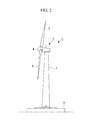
- a wind power generator 1 shown in Fig. 2 includes a pillar 2 provided upright on a base 6, a nacelle 3 installed at the upper end of the pillar 2, and a rotor head 4 provided on the nacelle 3 so as to be rotatable around a substantially horizontal axis.
- the rotor head 4 includes a plurality of (in the illustrated example, three) blades (wind turbine blade) 5 attached thereto radially around the axis of rotation thereof.
- the illustrated wind power generator 1 is of what is called an up wind type in which the blades 5 rotate in front of the nacelle 3.
- the wind power generator 1 for example, hydraulic pressure is used for a pitch controller configured to individually control the blade pitch angles of the blades 5.
- the wind power generator 1 also includes a lubricator configured to supply lubricant oil to rotating and sliding portions such as a bearing that supports a spindle rotating integrally with the blades 5 and a gear box that increases the rotation speed of the blades 5 and spindle.
- An oil supply pump configured to feed hydraulic operating oil or lubricant oil is used for the pitch controller and the lubricator.
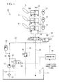
- Fig. 1 shows the pitch controller 10 for the blades 5 as an example of a general configuration of the oil supply pump and its peripheral equipment.
- the pitch controller 10 can individually hydraulically control the blade pitch angles of the three blades 5 attached to the rotor head 4.
- reference numeral 11 denotes an oil tank in which hydraulic operating oil is stored.
- Reference numeral 12 denotes a hydraulic pump driven by an electric motor 13.
- Reference numeral 14 denotes a servo valve configured to switch the flow direction of hydraulic pressure.
- Reference numeral 15 denotes a blade pitch cylinder configured to vary the blade pitch angle of each of the blades 5.
- Reference numerals 16 and 17 denote a safety valve and an emergency stop valve, respectively.
- Reference numerals 18 and 19 denote accumulators.
- Reference numerals 20 and 21 denote a check valve and straightener, respectively. These pieces of equipment are connected together by a hydraulic pipe 22 so as to form the pitch controller 10.
- the electric motor 13 is classified into a fixed capacity type and a variable capacity type, and the present embodiment uses the electric motor 13 of the fixed capacity type.
- the electric motor drives a hydraulic pump 12 such as a gear pump which has a discharge amount varying depending on the rotation speed.
- the pitch controller 10 includes a controller 30 configured to receive a blade pitch angle control signal and the like to control the operation of the electric motor 13, the channel switching operation of the servo valve 14, the operation of the emergency stop valve 17, and the like.
- the pitch controller 10 is also stopped, preventing the electric motor 13 and the hydraulic pump 12 from being operated.
- the servo valve 14 switches the hydraulic channel depending on the direction in which the pitch angle of the blade 5 is changed.
- the hydraulic operating oil supplied to blade pitch cylinder 15 presses a piston 15a rightward or leftward depending on the hydraulic channel set by the servo valve 14.
- the blade 5 coupled to the piston rod 15b is pivotally moved depending on the direction in which the piston 15a and the piston rod 15b move.
- the blade 5 is thus adjusted to the desired blade pitch angle.
- the piston 15a fed with hydraulic operating oil moves through the blade pitch cylinder 15 to press the opposite hydraulic operating oil.
- the hydraulic operating oil pressed by the piston 15a passes through the servo valve 15 and a return channel 23 back to the oil tank 11.
- the safety vale 16 is open in an abnormal state in which a hydraulic circuit is at a high pressure with a predetermined value or larger.
- the hydraulic operating oil supplied by the hydraulic pump 12 is returned through the return channel 24 to the oil tank 11.
- the emergency stop valve 17 is a normally closed electromagnetic valve and is opened, for example, when the servo valve 14 becomes defective, to supply hydraulic operating oil to a predetermined side of the blade pitch cylinder 15.
- the blade 5 can move pivotally to a predetermined emergency stop position to deal with the defect in the pitch controller 10.
- the pitch controller 10 of the above-described wind power generator 1 includes a bypass channel 25 branching off from an discharge side channel of the hydraulic supply pump 12 and connected to the oil tank 11, an electromagnetic valve 26 provided in the bypass channel 25 so as to serve as an on-off valve which is opened when the hydraulic pump 12 is started, a temperature sensor (temperature detecting section) 31 configured to detect the oil temperature of hydraulic operating oil, and a control section configured to carry out pump inching after the hydraulic pump 12 has been started, to raise the temperature of the hydraulic operating oil to a predetermined value.
- the control section includes required circuits and the like incorporated in the controller 30.
- the temperature of the hydraulic operating oil is lowered by the outside air temperature. This leads to the increased viscosity and significantly degraded fluidity of the hydraulic operating oil.
- the oil pump 12 starts operation in order to start or resume operating the wind power generator 1
- the oil temperature of the hydraulic operating oil is lower than a predetermined value
- pump inching is carried out in which the hydraulic pump 12 is repeatedly started and stopped in a short time.
- the hydraulic operating oil is gradually supplied to the piping system of the hydraulic pipe 22.
- the oil temperature in the oil tank 11 detected by the temperature sensor 31 may be adopted as the oil temperature of the hydraulic operating oil.
- the controller 30 initially opens the electromagnetic valve 26 to make the bypass channel 25 active. Thereafter, a pulse wave is input to the fixed-capacity electric motor 13 to carry out pump inching in which the hydraulic pump 12 performs an ON/OFF operation corresponding to the pulse wave. Then, the hydraulic pump 12 is repeatedly operated and stopped in a short time. Such pump inching is continued until the temperature sensor 31 detects that the oil temperature has increased to a predetermined value.
- the oil temperature of the hydraulic operating oil supplied to the hydraulic pipe 22 rises gradually to the predetermined value as a result of the friction between the hydraulic operating oil and the piping wall surface, the self-friction of the hydraulic operating oil, and the like.
- the bypass channel 25 since the bypass channel 25 is active, the hydraulic operating oil can return through the bypass channel 25 to the oil tank 11.
- the internal pressure of the hydraulic pipe 22 can be prevented from increasing rapidly.
- the above-described pump inching can be carried out by transmitting a pulse wave to the electric motor 13.
- the present apparatus eliminates the need to add a large-scale facility. That is, existing facilities can be effectively utilized to prevent or suppress a possible increase in the difference in temperature between the hydraulic operating oil and both the piping and equipment. As a result, the piping and equipment can be reliably and inexpensively prevented from being damaged by heat shock or the like.
- the electric motor 13 for the hydraulic pump 12 is of a fixed capacity type.
- an electric motor 13A configured to drive the hydraulic pump 12 may be of a variable capacity type, and a controller 30A may control a current value provided to the electric motor 13A to carry out pump inching.
- the rotation speed of the variable-capacity electric motor 13A varies depending on the current value provided by the power source.
- pump inching can be carried out so that the hydraulic pump 12 is repeatedly operated and stopped in a short time.
- existing facilities can be effectively utilized to prevent or suppress a possible increase in the difference in temperature between the hydraulic operating oil and both the piping and equipment.
- the piping and equipment can be reliably and inexpensively prevented from being damaged by heat shock or the like.
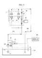
- Fig. 2 shows an essential part of an example of a general configuration of an oil supply pump and its peripheral equipment in a pitch controller 10. Components similar to those of the above-described embodiment are denoted by the same reference numerals and will not be described below in detail.
- the second embodiment is different from the first embodiment in that the above-described pump inching is not carried out but a hydraulic pump 12A of a variable capacity type is adopted as an oil supply pump to supply a hydraulic pipe 22 with a flow rate of hydraulic operating oil corresponding to the oil temperature.
- the hydraulic pump 12A is of a variable discharge amount type that discharges a variable amount of oil like, for example, a swash plate pump.
- a controller 30B includes a control section configured to control the flow rate of the hydraulic pump 12A when the hydraulic pump 12A starts or resumes operation, to raise the temperature of the hydraulic operating oil to a predetermined value.
- the flow rate of the hydraulic pump 12A is controlled so as to gradually supply hydraulic operating oil to the hydraulic pipe 22.
- the oil temperature of hydraulic operating oil supplied to the hydraulic pipe 22 rises to a predetermined value as a result of friction with the hydraulic pipe 22 and the self-friction of the hydraulic operating oil.
- a rapid change in temperature is reduced.
- an electromagnetic valve 26 in a bypass channel 25 is open.
- the hydraulic pipe 22 can be prevented from undergoing a rapid pressure increase.
- the above-described invention can provide a wind power generator configured to take a measure against a decrease in oil temperature based on pump inching effectively utilizing existing facilities or flow rate control using a variable-discharge-amount pump, that is, a measure against a decrease in oil temperature which measure eliminates the need to add a new large-capacity power source.
- the target oil is hydraulic operating oil for the pitch controller 10.
- the present invention is not limited to this aspect.
- the present invention is also applicable to, for example, lubricant oil supplied to rotating and sliding portions provided in the bearing and gear box of the wind power generator 1.
- a lubricant oil pump 12B is operated to supply lubricant oil in an oil tank 11A to a bearing 41 and a meshing portion of a gear 42 which are rotating and sliding portions of the gear box 50.
- a gear pump driven by an electric motor 13 of a fixed capacity type is used as the lubricant oil pump 12B.
- Lubricant oil discharged by the lubricant oil pump 12B is fed through a lubricant oil supply pipe 22A to the bearing 41 and the gear 42.
- the lubricant oil lubricates required portions and is then returned through a lubricant oil return channel 23A to the oil tank 11.
- the lubricant oil system configured as described above includes the bypass channel 25 branching off from a discharge side channel of the lubricant oil pump 12B and connected to the oil tank 11, the electromagnetic valve 26 provided in the bypass channel 25 so as to serve as an on-off valve opened when the lubricant oil pump 12B is started, a temperature sensor 31 configured to detect the oil temperature of lubricant oil, and a controller 30C configured to carry out pump inching after the hydraulic pump 12B has been started, to raise the temperature of the hydraulic operating oil to a predetermined value, the controller 30C including required circuits and the like incorporated therein.
- the temperature of the lubricant oil is lowered by the outside air temperature, leading to the increased viscosity and significantly degraded fluidity of the lubricant oil, then when the lubricant oil pump 12B starts operation in order to start or resume operating the wind power generator 1, the temperature of the lubricant oil is checked based on a detected value from the temperature sensor 31. As a result, if the oil temperature of the lubricant oil is lower than a predetermined value, pump inching is carried out in which the lubricant pump 12B is repeatedly started and stopped in a short timed. Thus, the lubricant oil is gradually supplied to the piping system of the lubricant oil supply pipe 22A.
- the controller 30C first opens the electromagnetic valve 26 to make the bypass channel 25 active. Thereafter, the controller 30C inputs a pulse wave to the fixed-capacity electric motor 13 to carry out pump inching in which the lubricant oil pump 12B performs an ON/OFF operation corresponding to the pulse wave. Thus, the lubricant oil pump 12B is repeatedly operated and stopped in a short time. Such pump inching is continued until the temperature sensor 31 detects that the oil temperature has increased to a predetermined value. Thus, the internal pressure of the hydraulic pipe 22 can be prevented from increasing rapidly.
- the above-described pump inching for the lubricant oil system is also not limited to the configuration in which the electric motor 13 of the fixed capacity type performs an ON/OFF operation in response to a pulse wave.
- An electric motor 13A of a variable capacity type may be adopted or the lubricant oil pump 12B may be of a variable capacity type.
- the present invention is not limited to the above-described embodiments and may be appropriately varied without departing from the spirits of the present invention.
Landscapes
- Engineering & Computer Science (AREA)
- Life Sciences & Earth Sciences (AREA)
- Sustainable Development (AREA)
- Sustainable Energy (AREA)
- Chemical & Material Sciences (AREA)
- Combustion & Propulsion (AREA)
- Mechanical Engineering (AREA)
- General Engineering & Computer Science (AREA)
- Wind Motors (AREA)
Applications Claiming Priority (1)
| Application Number | Priority Date | Filing Date | Title |
|---|---|---|---|
| PCT/JP2008/062183 WO2010001479A1 (ja) | 2008-07-04 | 2008-07-04 | 風力発電装置 |
Publications (2)
| Publication Number | Publication Date |
|---|---|
| EP2295796A1 true EP2295796A1 (de) | 2011-03-16 |
| EP2295796A4 EP2295796A4 (de) | 2013-06-19 |
Family
ID=41465595
Family Applications (1)
| Application Number | Title | Priority Date | Filing Date |
|---|---|---|---|
| EP08777898.1A Withdrawn EP2295796A4 (de) | 2008-07-04 | 2008-07-04 | Vorrichtung zur erzeugung von windenergie |
Country Status (9)
| Country | Link |
|---|---|
| US (1) | US20110012353A1 (de) |
| EP (1) | EP2295796A4 (de) |
| JP (1) | JP5260651B2 (de) |
| KR (1) | KR20100126766A (de) |
| CN (1) | CN101981313B (de) |
| AU (1) | AU2008358707A1 (de) |
| BR (1) | BRPI0822488A2 (de) |
| CA (1) | CA2718489A1 (de) |
| WO (1) | WO2010001479A1 (de) |
Cited By (2)
| Publication number | Priority date | Publication date | Assignee | Title |
|---|---|---|---|---|
| US8869940B2 (en) | 2012-01-17 | 2014-10-28 | General Electric Company | Dual temperature oil control system and method for a wind turbine gearbox |
| EP2573391B1 (de) | 2011-09-22 | 2018-11-21 | Moventas Gears Oy | Verfahren und Anordnung zur Steuerung der Schmierung eines Antriebssystems |
Families Citing this family (12)
| Publication number | Priority date | Publication date | Assignee | Title |
|---|---|---|---|---|
| CA2715920A1 (en) * | 2010-02-08 | 2011-08-08 | Mitsubishi Heavy Industries, Ltd. | Lubricant heating mechanism, gear mechanism, and wind turbine generator using the same |
| BRPI1001236A2 (pt) * | 2010-02-19 | 2016-02-10 | Mitsubishi Heavy Ind Ltd | métodos de arranque de uma máquina rotativa e de um gerador de turbina eólica |
| DK201070305A (en) * | 2010-06-30 | 2011-07-01 | Vestas Wind Sys As | A pitch system |
| FR2970504B1 (fr) | 2011-01-19 | 2013-02-08 | Turbomeca | Procede et dispositif d'alimentation en lubrifiant |
| FI20115793A0 (fi) * | 2011-08-12 | 2011-08-12 | Mervento Oy | Tuuliturbiinin lapakulman säätöjärjestelmä |
| EP2672112A1 (de) * | 2012-06-05 | 2013-12-11 | ZF Wind Power Antwerpen NV | Verfahren zur Schmierung eines Getriebes für eine Windturbine |
| CN105339652B (zh) * | 2013-04-29 | 2018-10-23 | 维斯塔斯风力系统有限公司 | 在寒冷气候环境中启动风轮机的方法 |
| CN105484949B (zh) * | 2016-02-01 | 2018-07-27 | 北京金风科创风电设备有限公司 | 风力发电机的轴承保护方法及装置 |
| US10697481B2 (en) * | 2016-02-29 | 2020-06-30 | Mitsubishi Heavy Industries, Ltd. | Wind turbine, control device for same, and control method for same |
| DE102018216618A1 (de) * | 2018-09-27 | 2020-04-02 | Zf Friedrichshafen Ag | Messanordnung für Schmierstoff |
| EP4102084A1 (de) * | 2021-06-11 | 2022-12-14 | Siemens Gamesa Renewable Energy A/S | Verfahren zum betrieb eines hydraulischen systems aus einem aus-zustand in einer kalten umgebung |
| FR3131274A1 (fr) * | 2021-12-23 | 2023-06-30 | Safran Aircraft Engines | Circuit de commande hydraulique de calage d’aubes de soufflante |
Family Cites Families (11)
| Publication number | Priority date | Publication date | Assignee | Title |
|---|---|---|---|---|
| JP2786582B2 (ja) * | 1993-07-28 | 1998-08-13 | 三菱重工業株式会社 | 風 車 |
| JPH08193591A (ja) * | 1994-01-20 | 1996-07-30 | Meiki Co Ltd | 油圧ポンプのインチング装置 |
| JPH11117914A (ja) * | 1997-10-17 | 1999-04-27 | Komatsu Ltd | 建設機械の油圧駆動装置 |
| JP4678096B2 (ja) * | 2001-04-27 | 2011-04-27 | コベルコ建機株式会社 | 建設機械の油圧回路 |
| DE10157714A1 (de) * | 2001-11-24 | 2003-06-26 | Daimler Chrysler Ag | Verfahren und Vorrichtungen zur Durchführung des Verfahrens zum Beeinflussen der Betriebstemperatur eines hydraulischen Betriebsmittels für ein Antriebsaggregat eines Fahrzeuges |
| ES2346639T3 (es) * | 2002-04-24 | 2010-10-19 | Vestas Wind Systems A/S | Turbina eolica, sistema hidraulico, sistema de purgado de aire y procedimiento de control de por lo menos dos palas de turbina eolica. |
| WO2004076855A1 (en) * | 2003-02-27 | 2004-09-10 | Avn Hydraulik A/S | Pitch regulation system |
| JP4233400B2 (ja) * | 2003-07-04 | 2009-03-04 | ナブテスコ株式会社 | 風車羽根のピッチ角駆動装置 |
| CN2675879Y (zh) * | 2003-11-11 | 2005-02-02 | 江苏省机电研究所有限公司 | 混凝土泵风扇驱动系统 |
| JP2005155698A (ja) * | 2003-11-21 | 2005-06-16 | Sumitomo (Shi) Construction Machinery Manufacturing Co Ltd | 油圧作業機械の油圧回路 |
| JP4858009B2 (ja) * | 2006-08-25 | 2012-01-18 | ダイキン工業株式会社 | 油圧システム |
-
2008
- 2008-07-04 CN CN2008801283640A patent/CN101981313B/zh not_active Expired - Fee Related
- 2008-07-04 US US12/933,449 patent/US20110012353A1/en not_active Abandoned
- 2008-07-04 KR KR1020107021436A patent/KR20100126766A/ko not_active Abandoned
- 2008-07-04 AU AU2008358707A patent/AU2008358707A1/en not_active Abandoned
- 2008-07-04 EP EP08777898.1A patent/EP2295796A4/de not_active Withdrawn
- 2008-07-04 BR BRPI0822488-9A patent/BRPI0822488A2/pt not_active IP Right Cessation
- 2008-07-04 CA CA2718489A patent/CA2718489A1/en not_active Abandoned
- 2008-07-04 JP JP2010518863A patent/JP5260651B2/ja not_active Expired - Fee Related
- 2008-07-04 WO PCT/JP2008/062183 patent/WO2010001479A1/ja not_active Ceased
Cited By (2)
| Publication number | Priority date | Publication date | Assignee | Title |
|---|---|---|---|---|
| EP2573391B1 (de) | 2011-09-22 | 2018-11-21 | Moventas Gears Oy | Verfahren und Anordnung zur Steuerung der Schmierung eines Antriebssystems |
| US8869940B2 (en) | 2012-01-17 | 2014-10-28 | General Electric Company | Dual temperature oil control system and method for a wind turbine gearbox |
Also Published As
| Publication number | Publication date |
|---|---|
| CN101981313B (zh) | 2013-07-10 |
| CN101981313A (zh) | 2011-02-23 |
| JPWO2010001479A1 (ja) | 2011-12-15 |
| JP5260651B2 (ja) | 2013-08-14 |
| WO2010001479A1 (ja) | 2010-01-07 |
| KR20100126766A (ko) | 2010-12-02 |
| EP2295796A4 (de) | 2013-06-19 |
| US20110012353A1 (en) | 2011-01-20 |
| CA2718489A1 (en) | 2010-01-07 |
| BRPI0822488A2 (pt) | 2015-06-16 |
| AU2008358707A1 (en) | 2010-01-07 |
Similar Documents
| Publication | Publication Date | Title |
|---|---|---|
| US20110012353A1 (en) | Wind power generator | |
| EP2351950B1 (de) | Schmierung eines Flüssigkeitsturbinengetriebes im Leerlauf oder bei Netzstromausfall | |
| EP3315769B1 (de) | Windturbine, steuerungsvorrichtung dafür und steuerungsverfahren dafür | |
| CN102725522B (zh) | 旋转机械的起动方法及风力发电装置的起动方法 | |
| EP2405145A2 (de) | Verfahren zur Überwachung einer Komponente in einem Hydraulikkreislauf, Überwachungsvorrichtung und Flüssigkeitsturbine | |
| EP3569872B1 (de) | Hydraulisches antriebssystem für sperrvorrichtung und ansteuerungsverfahren | |
| EP3450750A1 (de) | Verfahren und system zur diagnose einer windturbinenenergieerzeugungsvorrichtung | |
| KR20130083392A (ko) | 재생 에너지형 발전 장치 및 그 제어 방법 | |
| EP2626577A1 (de) | Verfahren zum Steuern einer Windturbine und Windturbine | |
| WO2004036056A1 (ja) | 油圧装置 | |
| CA2730677A1 (en) | Blade pitch controller, wind turbine generator, and method of controlling blade pitch | |
| EP4304845B1 (de) | Hydraulische oder oleodynamische oder pneumatische presse | |
| WO2017063654A1 (en) | Method for controlling hydraulic pitch force system | |
| US11519491B2 (en) | Gear unit with reduced power loss, operating method and industrial application | |
| EP2891795B1 (de) | Hydraulikgetriebe, Windturbinengenerator und Betriebssverfahren dafür | |
| KR101265435B1 (ko) | 회전 기계의 기동 방법 및 풍력 발전 장치의 기동 방법 | |
| CN113493119A (zh) | 一种移动式上料装置的控制系统及方法 | |
| JP2020020432A (ja) | 油脂供給装置およびそれを用いた風力発電システム |
Legal Events
| Date | Code | Title | Description |
|---|---|---|---|
| PUAI | Public reference made under article 153(3) epc to a published international application that has entered the european phase |
Free format text: ORIGINAL CODE: 0009012 |
|
| 17P | Request for examination filed |
Effective date: 20100928 |
|
| AK | Designated contracting states |
Kind code of ref document: A1 Designated state(s): AT BE BG CH CY CZ DE DK EE ES FI FR GB GR HR HU IE IS IT LI LT LU LV MC MT NL NO PL PT RO SE SI SK TR |
|
| AX | Request for extension of the european patent |
Extension state: AL BA MK RS |
|
| DAX | Request for extension of the european patent (deleted) | ||
| A4 | Supplementary search report drawn up and despatched |
Effective date: 20130516 |
|
| RIC1 | Information provided on ipc code assigned before grant |
Ipc: F03D 11/00 20060101AFI20130510BHEP |
|
| STAA | Information on the status of an ep patent application or granted ep patent |
Free format text: STATUS: THE APPLICATION HAS BEEN WITHDRAWN |
|
| 18W | Application withdrawn |
Effective date: 20140930 |