EP2297722B1 - Identification de régions d'intérêt et extraction de courbes de valeurs dans le temps dans des procédures d'imagerie - Google Patents
Identification de régions d'intérêt et extraction de courbes de valeurs dans le temps dans des procédures d'imagerie Download PDFInfo
- Publication number
- EP2297722B1 EP2297722B1 EP09770746.7A EP09770746A EP2297722B1 EP 2297722 B1 EP2297722 B1 EP 2297722B1 EP 09770746 A EP09770746 A EP 09770746A EP 2297722 B1 EP2297722 B1 EP 2297722B1
- Authority
- EP
- European Patent Office
- Prior art keywords
- enhancement
- interest
- time
- patient
- cluster
- Prior art date
- Legal status (The legal status is an assumption and is not a legal conclusion. Google has not performed a legal analysis and makes no representation as to the accuracy of the status listed.)
- Active
Links
Images


Classifications
-
- G—PHYSICS
- G06—COMPUTING OR CALCULATING; COUNTING
- G06T—IMAGE DATA PROCESSING OR GENERATION, IN GENERAL
- G06T7/00—Image analysis
- G06T7/0002—Inspection of images, e.g. flaw detection
- G06T7/0012—Biomedical image inspection
-
- G—PHYSICS
- G06—COMPUTING OR CALCULATING; COUNTING
- G06F—ELECTRIC DIGITAL DATA PROCESSING
- G06F18/00—Pattern recognition
- G06F18/20—Analysing
- G06F18/23—Clustering techniques
- G06F18/232—Non-hierarchical techniques
- G06F18/2321—Non-hierarchical techniques using statistics or function optimisation, e.g. modelling of probability density functions
- G06F18/23213—Non-hierarchical techniques using statistics or function optimisation, e.g. modelling of probability density functions with fixed number of clusters, e.g. K-means clustering
-
- G—PHYSICS
- G06—COMPUTING OR CALCULATING; COUNTING
- G06T—IMAGE DATA PROCESSING OR GENERATION, IN GENERAL
- G06T7/00—Image analysis
- G06T7/0002—Inspection of images, e.g. flaw detection
- G06T7/0012—Biomedical image inspection
- G06T7/0014—Biomedical image inspection using an image reference approach
- G06T7/0016—Biomedical image inspection using an image reference approach involving temporal comparison
-
- G—PHYSICS
- G06—COMPUTING OR CALCULATING; COUNTING
- G06T—IMAGE DATA PROCESSING OR GENERATION, IN GENERAL
- G06T7/00—Image analysis
- G06T7/10—Segmentation; Edge detection
- G06T7/11—Region-based segmentation
-
- G—PHYSICS
- G06—COMPUTING OR CALCULATING; COUNTING
- G06T—IMAGE DATA PROCESSING OR GENERATION, IN GENERAL
- G06T7/00—Image analysis
- G06T7/10—Segmentation; Edge detection
- G06T7/143—Segmentation; Edge detection involving probabilistic approaches, e.g. Markov random field [MRF] modelling
-
- G—PHYSICS
- G06—COMPUTING OR CALCULATING; COUNTING
- G06V—IMAGE OR VIDEO RECOGNITION OR UNDERSTANDING
- G06V10/00—Arrangements for image or video recognition or understanding
- G06V10/70—Arrangements for image or video recognition or understanding using pattern recognition or machine learning
- G06V10/762—Arrangements for image or video recognition or understanding using pattern recognition or machine learning using clustering, e.g. of similar faces in social networks
- G06V10/763—Non-hierarchical techniques, e.g. based on statistics of modelling distributions
-
- G—PHYSICS
- G06—COMPUTING OR CALCULATING; COUNTING
- G06T—IMAGE DATA PROCESSING OR GENERATION, IN GENERAL
- G06T2207/00—Indexing scheme for image analysis or image enhancement
- G06T2207/10—Image acquisition modality
- G06T2207/10072—Tomographic images
- G06T2207/10081—Computed x-ray tomography [CT]
-
- G—PHYSICS
- G06—COMPUTING OR CALCULATING; COUNTING
- G06T—IMAGE DATA PROCESSING OR GENERATION, IN GENERAL
- G06T2207/00—Indexing scheme for image analysis or image enhancement
- G06T2207/30—Subject of image; Context of image processing
- G06T2207/30004—Biomedical image processing
- G06T2207/30061—Lung
-
- G—PHYSICS
- G06—COMPUTING OR CALCULATING; COUNTING
- G06V—IMAGE OR VIDEO RECOGNITION OR UNDERSTANDING
- G06V2201/00—Indexing scheme relating to image or video recognition or understanding
- G06V2201/03—Recognition of patterns in medical or anatomical images
- G06V2201/031—Recognition of patterns in medical or anatomical images of internal organs
Definitions
- the present invention relates to identification of one or more regions of interest in imaging procedures and, particularly, to identification of one or more regions of interest with a minimum of or without manual intervention and subsequent extraction of time value curves for the one or more regions of interest.
- Contra enhancement media or contrast media in imaging procedures (for example, computed tomography or CT, magnetic resonance imaging or MRI, ultrasound imaging, etc.), is well known in the medical and imaging art.
- a bolus of a contrast medium is injected intravenously and is carried by blood flow to one or more regions of interest (for example, an organ or blood vessel).
- a transit, timing or test bolus scan a series of single-level or single-plane images are acquired at specified time intervals to determine how contrast propagates through a particular structure.
- one or more regions of interest or ROIs are selected by manually drawing shapes on a single slice. Subsequently, average enhancement within each hand-drawn region of interest is computed for every slice in the time series, generating 1-D curves.
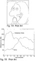
- Figure 1A illustrates an example of a scan upon which two regions of interest corresponding to the trunk of the pulmonary artery (P) and the aorta (A) have been hand drawn.
- Figure 1B illustrates a representative example of the time enhancement curves that are calculated from a transit, timing or test bolus performed as part of a cardiac Computed Tomography Angiogram or CTA procedure for the two regions of interest.
- Accurate and consistent placement of regions of interest in the pulmonary artery and the aorta (and/or other region(s) of interest) is important to achieve desirable results. Accurate and consistent placement of the regions of interest is especially important if the time enhancement curves are to be used for optimization of a diagnostic protocol to be used in an imaging scan. Determining the size, shape, and location of the regions of interest is challenging and requires valuable operator time (for example, to go to a separate evaluation screen, to load the images, to draw the region(s) of interest, and to use the resulting data to generate and/or adjust the contrast/scan protocol).
- tracking test bolus procedures an operator is required to mark one or more regions of interest prior to contrast being injected. It can be particularly difficult to draw the regions of interest on the image before contrast has been injected. Moreover, factors such as patient movement can result in substantial inaccuracies.
- Xiaohua, C. et al. disclose a scheme for simultaneous segmentation and registration of contrast-enhanced images of the breast obtained through magnetic resonance imaging.
- the scheme involves segmenting the breast into different regions, each corresponding to different tissue, and to identify tissue regions judged abnormal, based on the time enhancement data obtained from those images.
- the segmentation process involves analyzing the time series of images and computing an attribute factor for each pixel, which contains the information associated with each pixel.
- Registration involves spatial mapping of the series of images from the initial reference image to next image and so on. Registration of the images, which is necessary to compensate for the motion of the patient that occurs during the scan, involves computation of a similarity measure, which is based on the results of the segmentation.
- the present invention provides a method of extracting at least one time-value curve for use in a protocol to be used in an imaging procedure using an imaging system, the method in accordance with claim 1.
- a vector y x y x 0 y x 1 ... y x T ⁇ 1 y x T ----can, for example, be determined wherein y is a value of a pixel at location x.
- the segments can, for example, be computed using a clustering technique such as K-means clustering.
- K clusters can, for example, be computed by minimizing the sum of squares of distances between data points and K cluster centroids, wherein K is an integer corresponding to the predetermined number of correlated segments.
- Each centered and normalize pixel value can be assigned to the cluster to which it exhibits the minimum computed distance to the centroid.
- the actions of determining each cluster centroid, determining a distance from centered and normalized pixel values to each of the K cluster centroids and assigning/reassigning each centered and normalize pixel value to the cluster to which it exhibits the minimum computed distance to the centroid can be repeated until convergence, resulting in a segmented image having K segments corresponding to the determined K clusters.
- the method can further include filtering the segmented image to eliminate pixels that are not well correlated with neighboring pixels.
- Each pixel of the segmented image can, for example, be compared with all eight of its neighboring pixels in filtering.
- the method can further include morphologically opening the segmented image.
- the method can also include overlaying the segmented image upon a contrast enhanced bolus data set and computing enhancement profiles for each of the K segments.
- the method can also further include semantically labeling at least one of the enhancement profiles with a semantic label corresponding to a region of interest of the patient based upon at least one of the characteristics of the labeled enhancement profile as compared to at least one other computed enhancement profiles.
- the present invention provides system for extracting at least one time-value curve for use in to determining a protocol to be used in connection with an imaging procedure, the system in accordance with claim 18.
- the system can further includes a memory system in communicative connection with the at least one processor.
- the memory system has stored therein an algorithm executable by the at least one processor to compute the predetermined number of correlated segments of the imaged portion corresponding to the predetermined number of regions of interest of the patient.
- the system can, for example, be in communicative connection with the at least one imaging system.
- the system can, for example, be in communicative connection with the at least one injector system.
- At least a portion of the system is integrated with the at least one imaging system.
- at least a portion of the system can be integrated with the at least one injector system.
- one or more regions of interest are determined in a portion of a patient's body by the devices, systems and/or methods of the present invention via analysis of a plurality of datasets of values (for example, pixel values) of the portion of the patient's body (in a time series of such datasets) without the requirement that an operator manually draw or otherwise define the regions of interest.
- the dataset of values (for example, point values such as pixel intensity values) need not be displayed to an operator as a viewed image during determination of the one or more regions of interest.
- time value curves for example, time enhancement curves in the case that a contrast enhancement medium is injected
- the dataset series for example, a contrast-enhanced transit bolus image series
- the term "pixel" refers to a defined portion or piece (typically, the smallest portion or piece) of data in an M-dimensional dataset of the present invention.
- the M-dimensional datasets of the present invention correspond to two-dimensional datasets corresponding to a two-dimensional digital image wherein each pixel has a pixel value or intensity.
- Three-dimensional images can also be used and the term pixel as used herein includes the term "voxel.”
- Multidimensional datasets can, for example, be created using data from more than one type of imaging system (for example, a combination of data from CT and MRI systems).
- the same CT transit bolus series illustrated in Figure 1 is used as a representative example.
- Time enhancement curves for the pulmonary artery and for the aorta are computed.
- the devices, systems and methods of the present invention can be used in connection with generally any region(s) of interest and in connection with generally any imaging methodology (for example, CT, MRI etc.) in which energy is applied to a patient to produce a dataset or image.
- the devises, systems and methods of the present invention can be used without the injection of a contrast medium.
- each pixel intensity value of the computed digital images corresponds to a single spatial location, given little or no patient motion.
- y x (0) is the baseline enhancement for the pixel
- s is the change in signal due to blood flow
- ⁇ is a noise term (assumed in several embodiments of the present invention to be spatially and temporally independent).
- s x (t) For those pixels corresponding to an area through which blood does flow, s x (t) will be well correlated within a region of interest circumscribing a specific territory of the anatomy, (for example, all pixels in the pulmonary trunk will have a similar enhancement pattern).
- the data is first thresholded to exclude obviously non-contrast-enhanced regions (for example, compare the images of Figures 1A and 2 ).
- the dataset can, for example, include all points with at least one non-zero enhancement value in the time series.
- K-means clustering is an algorithm used to classify, group or segment objects based on attributes thereof into K groups, wherein K is a positive integer number.
- grouping is accomplished by minimizing the sum of squares of distances between data points and a corresponding cluster centroid.
- the distance metric used in the K-means clustering procedure was one minus the sample correlation between points (treated as sequences of values).
- Each cluster centroid was the component-wise mean of the points in that cluster, after centering and normalizing those points to, for example, zero mean and unit standard deviation.
- centroid 1 N ⁇ x ⁇ cluster y ⁇ x where N is the number of pixels in the cluster.
- the centroid is a T-dimensional, normalized enhancement profile.
- Other potential distance metrics could include Euclidean distance, sum of absolute differences (city-block distance), and the cosine of the two feature vectors.
- a similarity metric can be thought of as the inverse of a distance metric. The closer two elements are in the selected feature space, the shorter the distance and the greater the similarity.
- Each pixel was then assigned to the cluster to which it exhibited the minimum computed distance to the centroid.
- cluster assignments were (in several embodiments) defined as a state wherein cluster centroids and assignments were stable.
- convergence can be obtained when the points no longer switch clusters, switch clusters in a stable, oscillating or steady state manner or centroids are no longer changed.
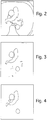
- a labeled or segmented image was generated as illustrated in Figure 2 wherein a first cluster or cluster 1 is represented by a gray color and a second cluster or cluster 2 is represented by a white color.
- each pixel value can be compared to one or more of its neighboring pixel values. In one embodiment, for each pixel, if all eight of its neighbors matched its own label or segment, the pixel kept its label or segment. Otherwise, the pixel was set to zero. This filtering process or procedure eliminates pixels on the edges of structures and those that are not correlated with their neighbors. Such filtering of the data of Figure 2 yielded the image of Figure 3 .
- a morphological opening (as known in the computer vision and image processing arts) was performed with, for example, a disc-shaped structuring element to eliminate small objects or islands (see Figure 4 ).
- morphological opening removes small objects/noise using a structuring element.
- Morphological opening can be defined as an erosion on an image followed by a dilation on the eroded image, using the same structuring element.
- a structuring element is superimposed on each of the foreground pixels. If the structuring element is not entirely contained within the foreground, the pixel at that coordinate is removed. Erosion causes foreground regions to shrink, removing isolated areas smaller than the structuring element.
- the structuring element is superimposed on each of the background pixels. If at least one pixel is contained within the foreground, the pixel at that coordinate is added.
- regions that were not removed during erosion are returned to their original size. Foreground borders are somewhat smoothed, and small islands are removed.
- each cluster can be given a semantic label as illustrated in Figure 5A .
- the pulmonary artery is known to peak first, so the cluster with the earlier time to peak was determined to be to the pulmonary artery.
- time-value curves (for example, time-enhancement curves) determined using the computed regions of interest of the present invention are used to facilitate determination of a protocol for an imaging procedure.
- protocol refers to injection parameters (in the case of injection of a contrast medium) and/or scanner/imaging system parameters for use in a procedure such as a diagnostic imaging scan.
- Injection parameters include, for example, flow rate, volume injected, injection duration, contrast agent concentration etc. that define, for example, the timing of, amount of, and/or the nature of fluid(s) to be delivered to a patient during an injection procedure. Such parameters can change over the course of the injection procedure.
- phase refers generally to a group of parameters that define, for example, the timing of, amount of, and/or the nature of fluid(s) to be delivered to a patient during a period of time (or phase duration) that can be less than the total duration of the injection procedure.
- the parameters of a phase provide a description of the injection over a time instance corresponding to the time duration of the phase.
- An injection protocol for a particular injection procedure can, for example, be described as uniphasic (a single phase), biphasic (two phases) or multiphasic (two or more phases, but typically more than two phases).
- Multiphasic injections also include injections in which the parameters can change continuously over at least a potion of the injection procedure.
- Scanner or imaging system parameters that can be determined include, but are not limited to, the amount of radiation transmitted to the patient, power inputs (for example, voltage or current), timing (for example, scan start time, stop time, delay time and/or duration).
- power inputs for example, voltage or current
- timing for example, scan start time, stop time, delay time and/or duration.
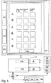
- an injection system such as a dual syringe injector system 100 as illustrated in Figure 6 and as, for example, disclosed in U.S. Patent No. 6,643,537 , Published U.S. Patent Application Publication No. 2004-0064041 and PCT International Patent Application No.
- PCT/US2007/026194 for use with the present invention includes two fluid delivery sources (sometimes referred to as source “A” and source “B” herein; such as syringes) that are operable to introduce a first fluid and/or a second fluid (for example, contrast enhancement fluid, saline etc.) to the patient independently (for example, simultaneously, simultaneously in different volumetric flow proportion to each other, or sequentially or subsequent to each other (that is, A then B, or B then A)).
- source A is in operative connection with a pressurizing mechanism such as a drive member 110A
- source B is in operative connection with a pressurizing mechanism such as a drive member 110B.
- the injection system includes a control system 200 in operative connection with injector system 100 that is operable to control the operation of drive members 110A and 110B to control injection of fluid A (for example, contrast medium) from source A and injection of fluid B (for example, saline) from source B, respectively.
- Control system 200 can, for example, include or be in communicative connection a user interface comprising a display 210.
- display 210 illustrates areas for parameters for injection flow rate, injection volume and injection duration for, for example, three phases of injection or fluid A and/or fluid B.
- the parameters for one or more such phases can be populated using one or more parameter generation systems and methods based at least in part on data obtained from time enhancement curves for regions of interest determined as described herein.
- Control system 200 can include a processor 220 (for example, a digital microprocessor as known in the art) in operative connection with a memory or memory system 230.
- processor 220 for example, a digital microprocessor as known in the art
- fluid delivery systems including multi-patient fluid delivery systems as, for example, disclosed in U.S. Patent Nos. 7,326,186 , 7,094,216 , 6,866,654 , 6,972,001 , 6,699,219 , 6,471,674 , 6,306,117 , 6,149,627 , 6,063,052 , 5,920,054 , 5,843,037 , 5,827,219 , 5,739,508 and 5,569,181 are also suitable for use in the present invention.
- Imaging system 300 can, for example, be a CT system, a Magnetic Resonance Imager (MRI) system, an ultrasound imaging system, or a Positron Emission Tomography (PET) system) or a Single Photon Emission Computed Tomography (SPECT) system as described above.
- the injection system can be in communicative connection with imaging system 300.
- Imaging system 300 and injector system 100 can, for example, be in communication connection via input/output ports (represented by terminations of arrows in Figure 6 ) as known in the art.
- imaging system 300 and injector system 100 are, for example, illustrated to be in communicative connection via a common communication hub 400. Alternatively, a direct communication link can be established.
- Imaging system 300 and injection systems 100 can be manually entered using one or more manual input systems (for example, keypads, keyboards mousse etc.) as know in the computer arts.
- Imaging system 300 and injector system or injector 100 can also be partially or fully integrated as described, for example, in Published PCT International Patent Application No. WO 2008/011401 .
- One, a plurality or all the illustrated components of the injection system and imaging system 300 can also or alternatively be integrated with or incorporated within another, separate component that is placed in communicative connection with other system components.
- Software embodying the systems and methods of the present invention can, for example, be embodied within one or more separate or standalone systems represented by system 500 which can, for example, include at least one processor (for example, a digital microprocessor), a memory system 520 a display 510 and a manual input system 505.
- system 500 is shown to be in communicative connection with communication hub 400.
- a direct communication link can also be established.
- Further data from one or more systems can be manually entered into one or more other systems using one or more manual input systems (for example, keypads, mouse etc.) as know in the computer arts.
- Software embodying the systems and methods of the present invention can, for example, be stored in memory 530 and executed by processor 520.
- all or a portion of the functionality of the methods and/or systems of the present invention can alternatively reside in an imaging system 300 (which can, for example, include at least one processor 320, a memory system 330, a display 310 and a manual input system 305) and/or in injector system 100.
- Data obtained from transit boluses using regions of interest as determined herein can be used in many ways to, for example, determine imaging procedure protocols.
- at least one parameter for an imaging procedure (which, includes the injection of a contrast enhancement fluid or medium which includes a contrast enhancing agent) is determined via a parameter generation system/methodology as described in, for example, PCT Application No. PCT/US08/67982 .
- discrete point data from one or more contrast enhancement curves for one or more regions of interest determined as described herein is substituted into a model to, for example, determine values for physiological variables in the model.
- the variables can, for example, be related to cardiopulmonary function.
- variables in a model that is predictive of temporal changes in concentration in a region or regions of interest within a patient are determined or estimated using data from at least one concentration profile for a pharmaceutical (that is, concentration as a function of time) in at least one region of interest.
- a number of discrete data points are taken from one or more contrast concentration profiles (that are, for example, provided by time enhancement curves generated using an imaging system) to provide an estimation of the values of such variables.
- contrast concentration profiles that are, for example, provided by time enhancement curves generated using an imaging system
- such variables are related to cardiopulmonary function (that is, cardiac, pulmonary and vascular function/dynamics).
- cardiac output (Q CO ) and blood volume (V B ) are unknown.
- Two discrete data points that is, two concentrations at two times are used to determine estimates of those variable.
- a time to peak enhancement for first region of interest enhancement T 1 and a time to peak enhancement for the second region of interest enhancement T 2 are input into the parameter generation system (algorithms for which can, for example, be embodied in software stored on one or more of memory systems 230, 330 and 530).
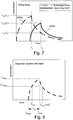
- the first region of interest is the pulmonary artery and the second region of interest is the ascending aorta (see, for example, Figure 7 ).
- Concentration at peak enhancement for the first region of interest enhancement C 1 (T 1 ) and concentration at peak enhancement for the second region of interest enhancement C 2 (T 2 ) are also input.
- C o t ⁇ Q inj Q co C i 1 ⁇ e ⁇ Q CO V B t t ⁇ T inj C o T inj e ⁇ Q CO V B t ⁇ T inj t > T inj
- Q inj [ml/s] is the injection flow rate
- T inj [s] is the injection duration
- Q CO is the cardiac output [ml/s]
- V B is the blood volume between the injection site and measurement point [ml]
- C i is the concentration of contrast in a contrast source from which contrast is injected into the patient
- C o (t) is the blood concentration in the region of interest of the agent at time t.
- T inj can, for example, be the amount of time between arrival of contrast enhancement agent and the time to peak enhancement.
- Contrast enhancing agent concentration on the first contrast enhancement curve at time T 2 can be related to a contrast enhancing agent concentration on the second contrast enhancement curves at time T 2 using the following equation C 1 T 2 ⁇ C 1 T 1 ⁇ C 2 T 2
- the concentration of contrast agent at peak enhancement C(T Peak ) at the time of peak enhancement T Peak in the second region of interest of an imaging injection can be related to the injection flow rate Q inj of the imaging injection and the injection duration T inj of the imaging injection using the formula:
- C T Peak Q inj Q CO C i 1 ⁇ e ⁇ Q CO V B T inj
- C(T Peak ) and C(T start ) enhancements can, for example, be determined for admissible input values for T inj and Q inj wherein a maximum Q inj and a minimum Q inj and a maximum T inj and a minimum T inj can be established.
- Maximum T inj can, for example, be established as a function of scan duration plus a constant, and minimum T inj can, for example, be established as the scan duration.
- the injection can be truncated if ( T inj + T arrRH ) > scanEnd.
- a duration of a dual flow phase wherein both contrast medium and a diluent are injected can also be determined.
- a ratio of contrast medium to diluent can be established for the dual flow phase.
- the end time of the dual flow phase can, for example be established to be equal to T inj .
- a protocol generation methodology as described above can, for example, be used to minimize the dose of contrast a subject receives by considering that subject's cardiac dynamics, drug properties and scan properties.
- the scan begins at T start , on an unknown point on the upslope of the left heart concentration curve.
- the scan ends ⁇ T seconds later (where ⁇ T is the specified scan duration) on the downslope of the curve.
- those two values referred to as C LH-Start on the upslope and C LH-End on the downslope
- C LH-Start on the upslope and C LH-End on the downslope should be as close to C LH-Target as possible.
- the right heart curve has similar associated parameters. However, because C RH-Peak should not occur during the scan window (as too much enhancement in the right heart could lead to streaking or beam hardening artifacts), it was not included as a term in the cost function set forth in Equation (9).
- parameters are added in the optimization procedure related to the dilution phase.
- the dilution ratio ( R 2 ) and the duration of the dilution phase ( ⁇ T inj2 ) can be added to the optimization procedure.
- the dilution ratio is thereby personalized (instead of using a fixed or set ratio of, for example, 40/60).
- Enhancement targets are also added to the optimization procedure (for example, cost function) for a second region of interest (the right heart or RH in the representative examples herein) in this embodiment.
- T start is thus also included as a parameter in the optimization procedure.
- Figure 9 illustrates an example of relative timing and diagnostic injection protocol phases, scan and enhancement curves for the right heart/pulmonary artery and left heart/aorta.
- ⁇ was set to equal 0.5 in several embodiments.
- ⁇ was set to equal 1 in several embodiments, which was shown to be a reasonable trade-off between losing consistency with the test bolus flow rate and not reaching target enhancement levels.
- y was set to equal 1000, which puts a very large penalty on exceeding the loaded contrast volume. In that regard, if ( Q inj ( R 1 ⁇ T inj 1 + R 2 ⁇ T inj 2 ) > V Load ) was true, y was set to equal 1000. Otherwise, y was set to equal 0.
- T start * , Q inj * , R 1 * , ⁇ T inj 1 * , R 2 * , ⁇ T inj 2 * arg min T start , Q inj , R 1 , ⁇ T inj 1 , R 2 , ⁇ T inj 2
- the RH and LH curves can each be in one of 3 regions - upslope (phase 1), dilution (phase 2), or decay (phase3).
- T ⁇ ( T arr + ⁇ T inj 1 ) the expression is:
- C T Q inj Q CO C i R 1 1 ⁇ e ⁇ Q CO V B T ⁇ T arr
- T arr is either T RH-arr or T LH-arr , depending on which curve is being used.
- T arr is either T RH-arr or T LH-arr , depending on which curve is being used.
Landscapes
- Engineering & Computer Science (AREA)
- Physics & Mathematics (AREA)
- Theoretical Computer Science (AREA)
- Computer Vision & Pattern Recognition (AREA)
- General Physics & Mathematics (AREA)
- Software Systems (AREA)
- General Health & Medical Sciences (AREA)
- Medical Informatics (AREA)
- Probability & Statistics with Applications (AREA)
- Health & Medical Sciences (AREA)
- Data Mining & Analysis (AREA)
- Nuclear Medicine, Radiotherapy & Molecular Imaging (AREA)
- Artificial Intelligence (AREA)
- Quality & Reliability (AREA)
- Radiology & Medical Imaging (AREA)
- Evolutionary Computation (AREA)
- Multimedia (AREA)
- Bioinformatics & Cheminformatics (AREA)
- Bioinformatics & Computational Biology (AREA)
- Evolutionary Biology (AREA)
- General Engineering & Computer Science (AREA)
- Life Sciences & Earth Sciences (AREA)
- Databases & Information Systems (AREA)
- Computing Systems (AREA)
- Apparatus For Radiation Diagnosis (AREA)
- Magnetic Resonance Imaging Apparatus (AREA)
- Image Processing (AREA)
Claims (23)
- Procédé d'extraction d'au moins une courbe de valeurs dans le temps pour utilisation dans la détermination d'un protocole devant être utilisé dans le cadre d'une procédure d'imagerie, le procédé comprenant :(a) la détermination d'une série d'ensembles de données M-dimensionnels 0 à T de valeurs de pixel à partir d'une série d'images d'une partie du corps d'un patient acquises au moyen d'un système d'imagerie, M étant un entier, T étant un entier, l'ensemble de données 0 correspondant à un ensemble de données à un temps t = 0, l'ensemble de données T correspondant à un ensemble de données à un temps t = T, et un pixel à un emplacement représenté par une variable x ayant un vecteur de profil d'accentuation défini comme :

 (b) le calcul, comme nombre prédéterminé de régions d'intérêt du corps du patient, d'un nombre prédéterminé de segments corrélés de la partie du corps du patient à partir de la série d'images de celui-ci par calcul d'une métrique de similitude des vecteurs de profil d'accentuation ;(c) le calcul de l'au moins une courbe de valeurs dans le temps pour au moins une du nombre prédéterminé de régions d'intérêt ; et(d) la détermination du protocole pour un système d'injection devant être utilisé dans le cadre de la procédure d'imagerie de telle sorte que le protocole soit basé au moins en partie sur des données issues de l'au moins une courbe de valeurs dans le temps.
 - Procédé de la revendication 1, dans lequel M = 2, faisant ainsi des ensembles de données M-dimensionnels des ensembles de données bidimensionnels.
- Procédé de la revendication 1, dans lequel M = 3, faisant ainsi des ensembles de données M-dimensionnels des ensembles de données tridimensionnels.
- Procédé de la revendication 1, dans lequel le nombre prédéterminé de segments corrélés de la partie du corps du patient calculé à partir de la série d'images de celui-ci correspondant au nombre prédéterminé de régions d'intérêt du corps du patient sont calculés au moyen d'un regroupement par la méthode des K-moyennes.
- Procédé de la revendication 4, dans lequel K groupes sont calculés par minimisation de la somme de carrés de distances entre points de données et K centroïdes de groupe, K étant un entier correspondant au nombre prédéterminé de segments corrélés.
- Procédé de la revendication 5, dans lequel les valeurs de pixel sont attribuées aléatoirement à un des K groupes et chacun des centroïdes de groupe est une moyenne sur les composantes des valeurs de pixel dans ce groupe après centrage et normalisation des valeurs de pixel sur une moyenne nulle et un écart type unitaire comme suit :

y x et l'écart type σx sont calculés au moyen des formules suivantes :
et
- Procédé de la revendication 6 dans lequel chacun des K centroïdes de groupe est déterminé au moyen de la formule suivante :

- Procédé de la revendication 7, dans lequel la distance entre les valeurs de pixel centrées et normalisées et chacun des K centroïdes de groupe est déterminée au moyen de la formule :

- Procédé de la revendication 8, dans lequel chacune des valeurs de pixel centrées et normalisées est attribuée au groupe pour lequel elle présente la distance calculée minimale jusqu'au centroïde.
- Procédé de la revendication 9, dans lequel les étapes déterminant chacun des K centroïdes de groupe, déterminant la distance entre les valeurs de pixel centrées et normalisées et chacun des K centroïdes de groupe et attribuant chacune des valeurs de pixel centrées et normalisées au groupe pour lequel elle présente la distance calculée minimale jusqu'au centroïde des revendications 7 à 9 sont répétées jusqu'à la convergence, ce qui se solde par une image segmentée ayant K segments correspondant aux K groupes.
- Procédé de la revendication 10, comprenant en outre le filtrage de l'image segmentée pour éliminer des pixels qui ne sont pas bien corrélés avec des pixels voisins.
- Procédé de la revendication 11, dans lequel chaque pixel de l'image segmentée est comparé avec l'ensemble de ses huit pixels voisins dans le filtrage.
- Procédé de la revendication 11, comprenant en outre l'ouverture morphologique de l'image segmentée.
- Procédé de la revendication 13, comprenant en outre la superposition de l'image segmentée sur un ensemble de données de bolus accentuées par contraste et le calcul de profils d'accentuation pour chacun des K segments.
- Procédé de la revendication 14, comprenant en outre l'étape de marquage sémantique d'au moins un des profils d'accentuation avec un marqueur sémantique correspondant à une région d'intérêt du corps du patient sur la base d'au moins une des caractéristiques du profil d'accentuation marqué tel que comparé à au moins un autre profil d'accentuation calculé.
- Procédé de la revendication 10, comprenant en outre la superposition de l'image segmentée sur un ensemble de données de bolus accentuées par contraste et le calcul du profil d'accentuation pour chacun des K segments.
- Procédé de la revendication 16, comprenant en outre l'étape de marquage sémantique d'au moins un des profils d'accentuation avec un marqueur sémantique correspondant à une région d'intérêt du corps du patient sur la base d'au moins une des caractéristiques du profil d'accentuation marqué tel que comparé à au moins un autre profil d'accentuation calculé.
- Système (100, 200, 300, 500) destiné à extraire au moins une courbe de valeurs dans le temps pour utilisation dans la détermination d'un protocole devant être utilisé dans le cadre d'une procédure d'imagerie, le système comprenant :(a) un système d'entrée (205, 305, 505) pour l'entrée de données délivrées depuis au moins un système d'imagerie (300), les données comprenant une série d'ensembles de données M-dimensionnels 0 à T de valeurs de pixel d'une partie imagée du corps d'un patient acquises au moyen de l'au moins un système d'imagerie, M étant un entier, T étant un entier, l'ensemble de données 0 correspondant à un ensemble de données à un temps t = 0, l'ensemble de données T correspondant à un ensemble de données à un temps t = T, et un pixel à un emplacement représenté par une variable x ayant un vecteur de profil d'accentuation défini comme :

 (b) au moins un processeur (220, 320, 520) relié de façon communicante au système d'entrée et adapté pour calculer (i), comme nombre prédéterminé de régions d'intérêt du corps du patient, un nombre prédéterminé de segments corrélés de la partie imagée en calculant une métrique de similitude des vecteurs de profil d'accentuation et (ii) l'au moins une courbe de valeurs dans le temps pour au moins une des régions d'intérêt ; et(c) au moins un système générateur de paramètres (100, 200, 300, 500) pour déterminer le protocole pour utilisation avec la procédure d'imagerie en utilisant l'au moins un système d'imagerie au moins en partie sur la base de données issues de l'au moins une courbe de valeurs dans le temps.
 - Système (100, 200, 300, 500) de la revendication 18, comprenant en outre un système de mémoire (230, 330, 530) relié de façon communicante à l'au moins un processeur (220, 320, 520), le système de mémoire ayant, stocké à l'intérieur, un algorithme exécutable par l'au moins un processeur pour calculer le nombre prédéterminé de segments corrélés de la partie imagée correspondant au nombre prédéterminé de régions d'intérêt du corps du patient.
- Système (100, 200, 300, 500) de la revendication 18, le système destiné à extraire l'au moins une courbe de valeurs dans le temps pour utilisation dans la détermination du protocole devant être utilisé dans le cadre de la procédure d'imagerie étant relié de façon communicante à l'au moins un système d'imagerie (300).
- Système (100, 200, 300, 500) de la revendication 18, le système destiné à extraire l'au moins une courbe de valeurs dans le temps pour utilisation dans la détermination du protocole devant être utilisé dans le cadre de la procédure d'imagerie étant relié de façon communicante à au moins un système d'injection (100).
- Système (100, 200, 300, 500) de la revendication 18, au moins une partie du système destiné à extraire l'au moins une courbe de valeurs dans le temps pour utilisation dans la détermination du protocole devant être utilisé dans le cadre de la procédure d'imagerie étant intégrée avec l'au moins un système d'imaqerie (300).
- Système de la revendication 18, au moins une partie du système destiné à extraire l'au moins une courbe de valeurs dans le temps pour utilisation dans la détermination du protocole devant être utilisé dans le cadre de la procédure d'imagerie étant intégrée avec au moins un système d'injection.
Applications Claiming Priority (2)
| Application Number | Priority Date | Filing Date | Title |
|---|---|---|---|
| US12/144,811 US8315449B2 (en) | 2008-06-24 | 2008-06-24 | Identification of regions of interest and extraction of time value curves in imaging procedures |
| PCT/US2009/047168 WO2009158212A1 (fr) | 2008-06-24 | 2009-06-12 | Identification de régions d’intérêt et extraction de courbes de valeurs dans le temps dans des procédures d'imagerie |
Publications (3)
| Publication Number | Publication Date |
|---|---|
| EP2297722A1 EP2297722A1 (fr) | 2011-03-23 |
| EP2297722A4 EP2297722A4 (fr) | 2016-06-01 |
| EP2297722B1 true EP2297722B1 (fr) | 2019-03-27 |
Family
ID=41431355
Family Applications (1)
| Application Number | Title | Priority Date | Filing Date |
|---|---|---|---|
| EP09770746.7A Active EP2297722B1 (fr) | 2008-06-24 | 2009-06-12 | Identification de régions d'intérêt et extraction de courbes de valeurs dans le temps dans des procédures d'imagerie |
Country Status (5)
| Country | Link |
|---|---|
| US (2) | US8315449B2 (fr) |
| EP (1) | EP2297722B1 (fr) |
| JP (2) | JP5555695B2 (fr) |
| CN (1) | CN102077264B (fr) |
| WO (1) | WO2009158212A1 (fr) |
Families Citing this family (30)
| Publication number | Priority date | Publication date | Assignee | Title |
|---|---|---|---|---|
| EP1812101A4 (fr) | 2004-11-16 | 2014-04-23 | Medrad Inc | Modelage de propagation pharmaceutique |
| DK2902053T3 (da) | 2004-11-24 | 2017-11-13 | Bayer Healthcare Llc | Anordninger, systemer og fremgangsmåder til væskefremføring |
| WO2011058459A1 (fr) * | 2009-11-16 | 2011-05-19 | Koninklijke Philips Electronics, N.V. | Imagerie fonctionnelle |
| US8891842B2 (en) * | 2010-02-02 | 2014-11-18 | Koninklijke Philips N.V. | Functional imaging |
| CA2803169C (fr) | 2010-06-24 | 2020-09-22 | Medrad, Inc. | Modelisation de propagation pharmaceutique et de generation de parametres pour protocoles d'injection |
| JP5750381B2 (ja) * | 2012-02-13 | 2015-07-22 | 株式会社日立製作所 | 領域抽出処理システム |
| HUE056182T2 (hu) | 2012-05-14 | 2022-01-28 | Bayer Healthcare Llc | Összeállítások és eljárások gyógyászati fluidum befecskendezési protokollok röntgencsõ-feszültség alapján történõ meghatározására |
| US9949696B2 (en) * | 2013-03-14 | 2018-04-24 | Tensys Medical, Inc. | Apparatus and methods for computing cardiac output of a living subject via applanation tonometry |
| WO2014185424A1 (fr) * | 2013-05-13 | 2014-11-20 | 株式会社 東芝 | Appareil d'analyse d'image médicale |
| JP6521575B2 (ja) * | 2013-06-11 | 2019-05-29 | キヤノンメディカルシステムズ株式会社 | X線コンピュータ断層撮影装置 |
| CN105022719B (zh) | 2014-04-23 | 2019-06-28 | Ge医疗系统环球技术有限公司 | 医学造影系统及方法 |
| EP3093678A1 (fr) | 2015-05-13 | 2016-11-16 | Bayer Pharma Aktiengesellschaft | Procédé pour optimiser la prédiction de l'heure d'arrivée du bolus en utilisant l'irm pour l'imagerie diagnostique |
| EP3224801B1 (fr) * | 2015-08-07 | 2021-12-15 | Shanghai United Imaging Healthcare Co., Ltd. | Système et procédé d'imagerie à modalités multiples |
| US10383590B2 (en) * | 2015-09-28 | 2019-08-20 | General Electric Company | Methods and systems for adaptive scan control |
| JP6571472B2 (ja) * | 2015-09-28 | 2019-09-04 | ザイオソフト株式会社 | 医用画像処理装置、医用画像撮像装置、医用画像処理方法、医用画像撮像方法、及び医用画像処理プログラム |
| US11484247B2 (en) * | 2016-07-01 | 2022-11-01 | Bostel Technologies, Llc | Phonodermoscopy, a medical device system and method for skin diagnosis |
| US11298072B2 (en) | 2016-07-01 | 2022-04-12 | Bostel Technologies, Llc | Dermoscopy diagnosis of cancerous lesions utilizing dual deep learning algorithms via visual and audio (sonification) outputs |
| US10026014B2 (en) * | 2016-10-26 | 2018-07-17 | Nxp Usa, Inc. | Method and apparatus for data set classification based on generator features |
| US10297038B2 (en) * | 2017-03-30 | 2019-05-21 | Siemens Healthcare Gmbh | Determination and presentation of flow transit curves |
| AU2018285887A1 (en) | 2017-06-16 | 2020-01-02 | Bayer Healthcare Llc | Systems and methods for split bolus protocol generation |
| CN108197567B (zh) * | 2017-12-29 | 2021-08-24 | 百度在线网络技术(北京)有限公司 | 用于图像处理的方法、装置和计算机可读介质 |
| CN110547821B (zh) * | 2018-05-31 | 2024-04-26 | 通用电气公司 | 追踪目标介入物的ct系统、方法及相关计算机可读介质 |
| US11341636B2 (en) * | 2019-11-01 | 2022-05-24 | GE Precision Healthcare LLC | Methods and systems for an adaptive five-zone perfusion scan |
| CN111127485B (zh) * | 2019-12-25 | 2023-07-14 | 东软集团股份有限公司 | 一种ct图像中目标区域提取方法、装置及设备 |
| JP7239511B2 (ja) * | 2020-02-26 | 2023-03-14 | 株式会社日立製作所 | 画像予測システム |
| CN111568459B (zh) * | 2020-06-03 | 2021-07-13 | 江苏省中医院 | 一种ct肺动脉成像扫描延迟时间的确定方法 |
| KR102671246B1 (ko) * | 2020-09-18 | 2024-06-03 | 세메스 주식회사 | 기판 처리 장치 및 기판 공정 처리의 정상 여부 판단 방법 |
| US11995831B2 (en) | 2021-04-09 | 2024-05-28 | Wisconsin Alumni Research Foundation | Method and apparatus for optimizing the use of contrast agents during medical imaging |
| JP7728687B2 (ja) * | 2021-10-29 | 2025-08-25 | キヤノンメディカルシステムズ株式会社 | 医用画像処理装置、医用画像処理方法、及びプログラム |
| WO2024083466A1 (fr) * | 2022-10-17 | 2024-04-25 | Bayer Aktiengesellschaft | Analyse automatisée d'images radiologiques |
Family Cites Families (187)
| Publication number | Priority date | Publication date | Assignee | Title |
|---|---|---|---|---|
| US3701345A (en) * | 1970-09-29 | 1972-10-31 | Medrad Inc | Angiographic injector equipment |
| US3812843A (en) * | 1973-03-12 | 1974-05-28 | Lear Siegler Inc | Method and apparatus for injecting contrast media into the vascular system |
| US3898983A (en) * | 1973-10-03 | 1975-08-12 | James O Elam | Device and method for detecting the degree of muscle relaxation of a medical patient |
| US3888239A (en) * | 1974-06-21 | 1975-06-10 | Morton K Rubinstein | Fluid injection system |
| US3941126A (en) | 1974-08-08 | 1976-03-02 | Dietrich Joseph W | Apparatus for long term intravenous administration of diluted incompatible multiple medications |
| JPS5226193A (en) | 1975-08-22 | 1977-02-26 | Houseikai | Remote control barium injector |
| US4135247A (en) * | 1977-08-15 | 1979-01-16 | Siemens Aktiengesellschaft | Tomography signal processing system |
| US4191183A (en) | 1977-10-31 | 1980-03-04 | Barry Mendelson | Mixing chamber for use in plural medical liquid intravenous administration set |
| US4151845A (en) * | 1977-11-25 | 1979-05-01 | Miles Laboratories, Inc. | Blood glucose control apparatus |
| US4187057A (en) | 1978-01-11 | 1980-02-05 | Stewart-Naumann Laboratories, Inc. | Peristaltic infusion pump and disposable cassette for use therewith |
| US4207871A (en) * | 1978-06-07 | 1980-06-17 | Imed Corporation | System for controlling the flow of intravenous fluids to a patient |
| US4280494A (en) * | 1979-06-26 | 1981-07-28 | Cosgrove Robert J Jun | System for automatic feedback-controlled administration of drugs |
| US4319568A (en) * | 1979-10-29 | 1982-03-16 | Vickers Limited | Liquid dispensing apparatus |
| JPS5675131A (en) | 1979-11-22 | 1981-06-22 | Olympus Optical Co | Endoscope apparatus |
| US4340153A (en) * | 1980-11-28 | 1982-07-20 | Spivey David L | Method and apparatus for medication dispensing |
| US4396385A (en) * | 1980-12-05 | 1983-08-02 | Baxter Travenol Laboratories, Inc. | Flow metering apparatus for a fluid infusion system |
| US4409966A (en) * | 1981-05-29 | 1983-10-18 | Lambrecht Richard M | Method and apparatus for injecting a substance into the bloodstream of a subject |
| US4392849A (en) * | 1981-07-27 | 1983-07-12 | The Cleveland Clinic Foundation | Infusion pump controller |
| US4447230A (en) | 1981-08-05 | 1984-05-08 | Quest Medical, Inc. | Intravenous administration set assembly |
| US4444198A (en) * | 1981-12-21 | 1984-04-24 | Petre John H | Circulatory monitoring system and method |
| DE3203594A1 (de) * | 1982-02-03 | 1983-08-11 | Siemens AG, 1000 Berlin und 8000 München | Roentgendiagnostikanlage fuer angiographische roentgenaufnahmen |
| JPS58152542A (ja) * | 1982-03-05 | 1983-09-10 | 株式会社東芝 | X線診断装置 |
| US4515584A (en) * | 1982-07-06 | 1985-05-07 | Fujisawa Pharmaceutical Co., Ltd. | Artificial pancreas |
| US4512764A (en) | 1982-09-27 | 1985-04-23 | Wunsch Richard E | Manifold for controlling administration of multiple intravenous solutions and medications |
| US4655197A (en) | 1982-12-01 | 1987-04-07 | Snyder Laboratories, Inc. | Lavage system with variable frequency, flow rate and pressure |
| US4479761A (en) * | 1982-12-28 | 1984-10-30 | Baxter Travenol Laboratories, Inc. | Actuator apparatus for a prepackaged fluid processing module having pump and valve elements operable in response to externally applied pressures |
| US4585941A (en) * | 1983-02-28 | 1986-04-29 | E. R. Squibb & Sons, Inc. | Dosimetry system for strontium-rubidium infusion pump |
| JPS59214431A (ja) * | 1983-05-20 | 1984-12-04 | 株式会社東芝 | 放射線診断装置 |
| GB8318670D0 (en) | 1983-07-11 | 1983-08-10 | Ici Plc | Fluid delivery apparatus |
| US4798590A (en) * | 1983-11-22 | 1989-01-17 | Medical Technology Products, Inc. | Intravenous infusion pumping system including independent pump set |
| US4559036A (en) | 1983-12-14 | 1985-12-17 | Wunsch Richard E | Apparatus for controlling administration of multiple intravenous solutions and medications |
| US4563175A (en) | 1983-12-19 | 1986-01-07 | Lafond Margaret | Multiple syringe pump |
| NL8304397A (nl) * | 1983-12-22 | 1985-07-16 | Philips Nv | Roentgenonderzoekapparaat met beeldsubstractie. |
| US4854324A (en) * | 1984-01-31 | 1989-08-08 | Medrad, Inc. | Processor-controlled angiographic injector device |
| US4551133A (en) | 1984-04-16 | 1985-11-05 | American Hospital Supply Corporation | Patient controlled medication infusion system |
| JPH0614746B2 (ja) | 1984-09-13 | 1994-02-23 | 株式会社東芝 | X線画像処理装置 |
| JPS61115539A (ja) * | 1984-11-09 | 1986-06-03 | 株式会社 日立メデイコ | デイジタル型x線撮影装置 |
| US4634426A (en) * | 1984-12-11 | 1987-01-06 | Baxter Travenol Laboratories | Medical infusion controller and user interface |
| US5088981A (en) * | 1985-01-18 | 1992-02-18 | Howson David C | Safety enhanced device and method for effecting application of a therapeutic agent |
| JPS61220628A (ja) | 1985-03-28 | 1986-09-30 | 株式会社 日立メデイコ | X線動態像計測装置 |
| DE3520044A1 (de) | 1985-06-04 | 1986-12-04 | Baxter Travenol Laboratories, Inc., Deerfield, Ill. | Anordnung zur verabreichung und/oder herstellung von medikament- und/oder naehrloesungen, insbesondere parenteralen naehrloesungen |
| US4710166A (en) | 1985-11-08 | 1987-12-01 | Quest Medical, Inc. | Automated drug additive infusion system |
| JPH072182B2 (ja) | 1986-04-07 | 1995-01-18 | テルモ株式会社 | 輸液ポンプ |
| US4750643A (en) | 1986-08-04 | 1988-06-14 | Sugrin Surgical Instrumentation, Inc. | Sterile fluid dispensing system and method |
| US4754786A (en) | 1986-09-05 | 1988-07-05 | Roderick Roberts | Sterile fluid storage and dispensing apparatus and method for filling same |
| SE457056B (sv) | 1987-01-29 | 1988-11-28 | Gambro Ab | System foer beredning av en vaetska avsedd foer en medicinsk behandling |
| US4887554A (en) | 1987-05-27 | 1989-12-19 | Whitford Darryl R | Animal drench |
| US4838856A (en) * | 1987-07-02 | 1989-06-13 | Truckee Meadows Research & Development | Fluid infusion flow control system |
| US4925444A (en) * | 1987-08-07 | 1990-05-15 | Baxter Travenol Laboratories, Inc. | Closed multi-fluid delivery system and method |
| US4880014A (en) | 1987-08-14 | 1989-11-14 | Zarowitz Barbara J | Method for determining therapeutic drug dosage using bioelectrical resistance and reactance measurements |
| US4795429A (en) | 1987-10-28 | 1989-01-03 | Feldstein Marvin A | Method and apparatus for use in the control of intravenous medication introduction |
| DE3739229A1 (de) * | 1987-11-19 | 1989-06-01 | Siemens Ag | Medizinische untersuchungsanlage |
| US5040537A (en) * | 1987-11-24 | 1991-08-20 | Hitachi, Ltd. | Method and apparatus for the measurement and medical treatment using an ultrasonic wave |
| US4874359A (en) * | 1987-12-14 | 1989-10-17 | White Frederick R | Power infuser |
| US4853521A (en) * | 1987-12-28 | 1989-08-01 | Claeys Ronald W | System for verifying and recording drug administration to a patient |
| GB8808305D0 (en) * | 1988-04-08 | 1988-05-11 | Nycomed As | Compositions |
| DE3817411A1 (de) * | 1988-05-21 | 1989-11-30 | Fresenius Ag | Mehrfachinfusionssystem |
| US4857056A (en) | 1988-07-06 | 1989-08-15 | Sherwood Medical Company | Auto-flush syringe pump |
| US4946439A (en) | 1988-08-15 | 1990-08-07 | Critikon, Inc. | Dual source parenteral infusion system with secondary infusion module |
| GB8822708D0 (en) | 1988-09-28 | 1988-11-02 | Core Consulting Group | Improved microwave-powered heating device |
| US4943279A (en) * | 1988-09-30 | 1990-07-24 | C. R. Bard, Inc. | Medical pump with infusion controlled by a detachable coded label |
| JPH02109546A (ja) * | 1988-10-18 | 1990-04-23 | Toshiba Corp | X線ct装置を用いた診断装置 |
| JP2781914B2 (ja) * | 1988-12-09 | 1998-07-30 | 日本アイデント・グラフ株式会社 | 連続立体撮影観察装置 |
| US5153827A (en) * | 1989-01-30 | 1992-10-06 | Omni-Flow, Inc. | An infusion management and pumping system having an alarm handling system |
| US5009654A (en) | 1989-03-10 | 1991-04-23 | Baxter International Inc. | Sterile product and method for sterilizing and assembling such product |
| US5032112A (en) | 1989-11-22 | 1991-07-16 | Baxter International Inc. | Dual source intravenous administration set having an intravenous pump |
| US5104374A (en) * | 1990-01-16 | 1992-04-14 | Bishko Jay R | Electronic fluid flow rate controller for controlling the infusion of intravenous drugs into a patient |
| US5078683A (en) * | 1990-05-04 | 1992-01-07 | Block Medical, Inc. | Programmable infusion system |
| FR2664153B1 (fr) * | 1990-07-06 | 1992-09-11 | Gen Electric Cgr | Systeme de radiodiagnostic pour examen angiographique avec dispositif automatique de suivi d'embole. |
| CA2045070A1 (fr) | 1990-07-31 | 1992-02-01 | Kazuaki Mizoguchi | Systeme de controle pour l'ans et l'actp |
| IL95743A (en) * | 1990-09-19 | 1993-02-21 | Univ Ramot | Method of measuring blood flow |
| US5180896A (en) * | 1990-10-11 | 1993-01-19 | University Of Florida | System and method for in-line heating of medical fluid |
| US5400792A (en) | 1990-11-20 | 1995-03-28 | Siemens Aktiengesellschaft | Medical diagnostics installation controllable from a central work station |
| US5339799A (en) * | 1991-04-23 | 1994-08-23 | Olympus Optical Co., Ltd. | Medical system for reproducing a state of contact of the treatment section in the operation unit |
| US5300031A (en) * | 1991-06-07 | 1994-04-05 | Liebel-Flarsheim Company | Apparatus for injecting fluid into animals and disposable front loadable syringe therefor |
| DE4218321A1 (de) * | 1991-12-09 | 1993-06-17 | Siemens Ag | Diagnostikanlage |
| AU3415893A (en) * | 1991-12-20 | 1993-07-28 | Abbott Laboratories | Automated drug infusion system with autopriming |
| AU3329793A (en) * | 1991-12-20 | 1993-07-28 | Abbott Laboratories | Infusion pump security system |
| JPH05290317A (ja) * | 1992-04-13 | 1993-11-05 | Mitsubishi Electric Corp | 磁気ヘッドおよびその製造方法 |
| US5382232A (en) * | 1992-03-13 | 1995-01-17 | Ivac Corporation | Infusion system with air-in-line clear function |
| DE4210120C1 (en) * | 1992-03-27 | 1993-08-05 | Siemens Ag, 8000 Muenchen, De | X=ray appts. for peripheral angiography - calculates relative positioning of appts. and patient support using data derived from patient |
| US5361761A (en) | 1992-06-17 | 1994-11-08 | Wisconsin Alumni Research Foundation | Method and apparatus for measuring blood iodine concentration |
| JP2636504B2 (ja) | 1992-07-27 | 1997-07-30 | シュナイダー・(ユーエスエイ)・インコーポレーテッド | 注入内腔を有する拡大カテーテル |
| US5383858B1 (en) * | 1992-08-17 | 1996-10-29 | Medrad Inc | Front-loading medical injector and syringe for use therewith |
| US5310997A (en) | 1992-09-10 | 1994-05-10 | Tandy Corporation | Automated order and delivery system |
| US5328463A (en) | 1992-09-18 | 1994-07-12 | Namic U.S.A. Corporation | Contrast media and fluid introduction system |
| US5338662A (en) * | 1992-09-21 | 1994-08-16 | Bio-Preserve Medical Corporation | Organ perfusion device |
| US5378231A (en) | 1992-11-25 | 1995-01-03 | Abbott Laboratories | Automated drug infusion system |
| GB9225014D0 (en) * | 1992-11-30 | 1993-01-20 | Univ Hospital London Dev Corp | Pulse injector for quantitative angiographic blood-flow measurements |
| WO1994015664A1 (fr) | 1993-01-07 | 1994-07-21 | Man Fai Shiu | Tubulure |
| US5474683A (en) | 1993-03-03 | 1995-12-12 | Deka Products Limited Partnership | Peritoneal dialysis systems and methods employing pneumatic pressure and temperature-corrected liquid volume measurements |
| EP0619122A1 (fr) | 1993-04-08 | 1994-10-12 | Getz Bros. Co.,Ltd. | Système de contrôle de seringue pour DSA et PTCA |
| US5472403A (en) | 1993-05-11 | 1995-12-05 | The Regents Of The University Of California | Device for automatic injection of radionuclide |
| US5385540A (en) * | 1993-05-26 | 1995-01-31 | Quest Medical, Inc. | Cardioplegia delivery system |
| US5417213A (en) * | 1993-06-07 | 1995-05-23 | Prince; Martin R. | Magnetic resonance arteriography with dynamic intravenous contrast agents |
| US5469849A (en) | 1993-06-14 | 1995-11-28 | Kabushiki Kaisha Toshiba | Ultrasound diagnosis apparatus |
| DE4320365C2 (de) * | 1993-06-19 | 2000-07-13 | Uvo Hoelscher | Mehrkanal-Dosiersystem |
| US5456255A (en) * | 1993-07-12 | 1995-10-10 | Kabushiki Kaisha Toshiba | Ultrasonic diagnosis apparatus |
| FR2708166A1 (fr) * | 1993-07-22 | 1995-01-27 | Philips Laboratoire Electroniq | Procédé de traitement d'images numérisées pour la détection automatique de sténoses. |
| US5368562A (en) | 1993-07-30 | 1994-11-29 | Pharmacia Deltec, Inc. | Systems and methods for operating ambulatory medical devices such as drug delivery devices |
| US5515851A (en) | 1993-07-30 | 1996-05-14 | Goldstein; James A. | Angiographic fluid control system |
| US5569181A (en) | 1993-10-28 | 1996-10-29 | Medrad, Inc. | Sterility assurance for contrast delivery system |
| US5827219A (en) | 1993-10-28 | 1998-10-27 | Medrad, Inc. | Injection system and pumping system for use therein |
| DE69432167T2 (de) * | 1993-10-28 | 2003-07-24 | Medrad, Inc. | System zur Kontrastmittelabgabe |
| EP0650738B1 (fr) | 1993-10-28 | 2003-05-02 | Medrad, Inc. | Système pour administrer des liquides à plusieurs malades |
| US5431627A (en) | 1993-11-12 | 1995-07-11 | Abbott Laboratories | Cassette identification system for use with a multi-program drug infusion pump |
| US5494036A (en) * | 1993-11-26 | 1996-02-27 | Medrad, Inc. | Patient infusion system for use with MRI |
| US5531679A (en) * | 1994-03-14 | 1996-07-02 | Schulman; Joseph H. | Fluidic infusion system for catheter or probe |
| US5881124A (en) * | 1994-03-31 | 1999-03-09 | Arch Development Corporation | Automated method and system for the detection of lesions in medical computed tomographic scans |
| US5458128A (en) * | 1994-06-17 | 1995-10-17 | Polanyi; Michael | Method and apparatus for noninvasively measuring concentration of a dye in arterial blood |
| EP0692766B1 (fr) | 1994-07-12 | 2002-05-08 | Medrad, Inc. | Circuit d'information en cercle ferme pour méthode de distribution de fluide médical |
| US5840026A (en) * | 1994-09-21 | 1998-11-24 | Medrad, Inc. | Patient specific dosing contrast delivery systems and methods |
| US6397098B1 (en) | 1994-09-21 | 2002-05-28 | Medrad, Inc. | Data communication and control for medical imaging systems |
| US5522798A (en) * | 1994-10-17 | 1996-06-04 | Abbott Laboratories | Control of a multi-channel drug infusion pump using a pharmacokinetic model |
| US5459769A (en) * | 1994-11-09 | 1995-10-17 | General Electric Company | Procedure for monitoring contrast agent application in a CT imaging system |
| US5724976A (en) * | 1994-12-28 | 1998-03-10 | Kabushiki Kaisha Toshiba | Ultrasound imaging preferable to ultrasound contrast echography |
| US5573515A (en) | 1995-04-20 | 1996-11-12 | Invasatec, Inc. | Self purging angiographic injector |
| US6656157B1 (en) | 1995-04-20 | 2003-12-02 | Acist Medical Systems, Inc. | Infinitely refillable syringe |
| US6099502A (en) | 1995-04-20 | 2000-08-08 | Acist Medical Systems, Inc. | Dual port syringe |
| US7267666B1 (en) * | 1995-04-20 | 2007-09-11 | Acist Medical Systems, Inc. | Angiographic injector system with multiple processor redundancy |
| US5743266A (en) * | 1995-04-25 | 1998-04-28 | Molecular Biosystems, Inc. | Method for processing real-time contrast enhanced ultrasonic images |
| US5687208A (en) | 1995-10-06 | 1997-11-11 | Bhb General Partnership | Method of and apparatus for predicting computed tomography contrast enhancement with feedback |
| US5583902A (en) | 1995-10-06 | 1996-12-10 | Bhb General Partnership | Method of and apparatus for predicting computed tomography contrast enhancement |
| FR2744058B1 (fr) | 1996-01-31 | 1998-04-30 | Canon Research Centre France S | Procede et dispositif d'economie d'energie pour systeme de transfert d'images |
| US5713358A (en) * | 1996-03-26 | 1998-02-03 | Wisconsin Alumni Research Foundation | Method for producing a time-resolved series of 3D magnetic resonance angiograms during the first passage of contrast agent |
| AU2454397A (en) * | 1996-04-24 | 1997-11-12 | Shriners Hospital For Children | Method and apparatus for recording three-dimensional topographies |
| US5796862A (en) | 1996-08-16 | 1998-08-18 | Eastman Kodak Company | Apparatus and method for identification of tissue regions in digital mammographic images |
| US5865744A (en) * | 1996-09-16 | 1999-02-02 | Lemelson; Jerome H. | Method and system for delivering therapeutic agents |
| DE19647701A1 (de) | 1996-11-08 | 1998-05-14 | Schering Ag | Vorrichtung zur Erzielung von konstanten Dichten von Kontrastmitteln in Geweben und Organen |
| US6236706B1 (en) * | 1996-12-12 | 2001-05-22 | General Electric Company | Methods and apparatus for predicting contrast agent uptake in a computed tomography system |
| EP0885616A1 (fr) * | 1997-06-20 | 1998-12-23 | Schering Aktiengesellschaft | Utilisation d'agents de contraste à administration intraveneuse, et appareil pour la mammographie |
| US6073042A (en) * | 1997-09-25 | 2000-06-06 | Siemens Medical Systems, Inc. | Display of three-dimensional MRA images in which arteries can be distinguished from veins |
| US5924987A (en) * | 1997-10-06 | 1999-07-20 | Meaney; James F. M. | Method and apparatus for magnetic resonance arteriography using contrast agents |
| DE19811349C1 (de) * | 1998-03-16 | 1999-10-07 | Siemens Ag | Verfahren zur Kontrastmittelverfolgung mittels eines bildgebenden medizinischen Geräts und Steuervorrichtung zur Durchführung des Verfahrens |
| US6381486B1 (en) * | 1999-01-08 | 2002-04-30 | Wisconsin Alumni Research Foundation | Magnetic resonance angiography with vessel segmentation |
| US6554798B1 (en) | 1998-08-18 | 2003-04-29 | Medtronic Minimed, Inc. | External infusion device with remote programming, bolus estimator and/or vibration alarm capabilities |
| AU2622800A (en) * | 1999-01-21 | 2000-08-07 | Metasensors, Inc. | Non-invasive cardiac output and pulmonary function monitoring using respired gasanalysis techniques and physiological modeling |
| US6478735B1 (en) | 1999-01-28 | 2002-11-12 | The United States Of America As Represented By The Administrator Of The National Aeronautics And Space Administration | Physiological feedback method and system |
| US6556695B1 (en) * | 1999-02-05 | 2003-04-29 | Mayo Foundation For Medical Education And Research | Method for producing high resolution real-time images, of structure and function during medical procedures |
| US6317623B1 (en) | 1999-03-12 | 2001-11-13 | Medrad, Inc. | Apparatus and method for controlling contrast enhanced imaging procedures |
| US6055985A (en) * | 1999-04-09 | 2000-05-02 | B.H.B., L.C. | Methods for injecting a contrast medium to generate prolonged uniform vascular enhancement |
| US6635030B1 (en) * | 1999-04-09 | 2003-10-21 | B.H.B. Llc | Contrast injector for injecting a contrast medium to generate prolonged uniform vascular enhancement |
| US6339718B1 (en) | 1999-07-30 | 2002-01-15 | Medrad, Inc. | Programmable injector control |
| US6387098B1 (en) | 1999-10-21 | 2002-05-14 | Peter Alexander Cole | Intramedullary catheter nail apparatus and method |
| US6673033B1 (en) * | 1999-11-24 | 2004-01-06 | Medrad, Inc. | Injectors, injector systems and injector control |
| US6652489B2 (en) | 2000-02-07 | 2003-11-25 | Medrad, Inc. | Front-loading medical injector and syringes, syringe interfaces, syringe adapters and syringe plungers for use therewith |
| AU2001247494A1 (en) * | 2000-03-30 | 2001-10-15 | Wisconsin Alumni Research Foundation. | Magnetic resonance angiography with automated vessel segmentation |
| US6626862B1 (en) * | 2000-04-04 | 2003-09-30 | Acist Medical Systems, Inc. | Fluid management and component detection system |
| US6471674B1 (en) | 2000-04-21 | 2002-10-29 | Medrad, Inc. | Fluid delivery systems, injector systems and methods of fluid delivery |
| US7094216B2 (en) | 2000-10-18 | 2006-08-22 | Medrad, Inc. | Injection system having a pressure isolation mechanism and/or a handheld controller |
| KR100722596B1 (ko) * | 2001-04-19 | 2007-05-28 | 가부시끼가이샤 도시바 | 화상처리방법과 화상처리장치 |
| US6775764B1 (en) | 2001-04-24 | 2004-08-10 | Cisco Technology, Inc | Search function for data lookup |
| US6597938B2 (en) * | 2001-08-16 | 2003-07-22 | Koninklijke Philips Electronics, N.V. | System for assistance of parameter determination and diagnosis in MRI dynamic uptake studies |
| JP4363833B2 (ja) * | 2001-10-16 | 2009-11-11 | 株式会社東芝 | 局所血流動態に関するインデックスを演算する方法及び装置 |
| US6745066B1 (en) * | 2001-11-21 | 2004-06-01 | Koninklijke Philips Electronics, N.V. | Measurements with CT perfusion |
| US6512807B1 (en) * | 2001-11-21 | 2003-01-28 | Koninklijke Philips Electronics, N.V. | Low signal correction for perfusion measurements |
| US7291126B2 (en) | 2001-11-26 | 2007-11-06 | Nilimedix Ltd. | Drug delivery device and method |
| ATE301483T1 (de) * | 2001-11-30 | 2005-08-15 | Brainlab Ag | Vorrichtung zur planung einer infusion |
| JP4230724B2 (ja) | 2001-12-20 | 2009-02-25 | 株式会社東芝 | X線コンピュータ断層撮影装置 |
| US6776764B2 (en) * | 2002-03-01 | 2004-08-17 | University Of Pittsburgh Of The Commonwealth System Of Higher Education | Use of aortic pulse pressure and flow in bedside hemodynamic management |
| US7457804B2 (en) | 2002-05-10 | 2008-11-25 | Medrad, Inc. | System and method for automated benchmarking for the recognition of best medical practices and products and for establishing standards for medical procedures |
| US7553294B2 (en) | 2002-05-30 | 2009-06-30 | Medrad, Inc. | Syringe plunger sensing mechanism for a medical injector |
| DE10230877A1 (de) | 2002-07-09 | 2004-02-12 | Siemens Ag | Kernspintomographiegerät mit einer Einrichtung zur graphischen Planung Kontrastmittel-gestützter angiographischer Messungen |
| US7267667B2 (en) | 2002-07-11 | 2007-09-11 | Boston Scientific Scimed, Inc. | Fluid management system for coronary intervention |
| US6929619B2 (en) | 2002-08-02 | 2005-08-16 | Liebel-Flarshiem Company | Injector |
| US20040025452A1 (en) * | 2002-08-12 | 2004-02-12 | Mclean Frederick Bruce | Baluster retaining member |
| JP4620929B2 (ja) * | 2002-09-26 | 2011-01-26 | 株式会社根本杏林堂 | 薬液注入装置 |
| US6866653B2 (en) * | 2002-10-31 | 2005-03-15 | Kyongtae T. Bae | Method and apparatus for sequential delivery of multiple injectable substances stored in a prefilled syringe |
| JP2004222864A (ja) * | 2003-01-21 | 2004-08-12 | Mitsubishi Research Institute Inc | 診断支援システム、診断支援方法及び診断支援プログラム |
| JP4731795B2 (ja) * | 2003-02-18 | 2011-07-27 | 株式会社根本杏林堂 | 薬液注入装置 |
| JP4459550B2 (ja) * | 2003-05-20 | 2010-04-28 | ジーイー・メディカル・システムズ・グローバル・テクノロジー・カンパニー・エルエルシー | 画像信号処理装置 |
| JP2005237825A (ja) * | 2004-02-27 | 2005-09-08 | Hitachi Medical Corp | 画像診断支援装置 |
| JP2005278690A (ja) * | 2004-03-26 | 2005-10-13 | Hiroshima Industrial Promotion Organization | コンピュータを用いた3次元胸部ct画像から結節状陰影を検出する方法およびその装置並びにコンピュータプログラム |
| DE102004043694B4 (de) * | 2004-09-09 | 2006-09-28 | Siemens Ag | Verfahren zur Segmentierung anatomischer Strukturen aus 3D-Bilddaten unter Nutzung topologischer Information |
| EP1812101A4 (fr) * | 2004-11-16 | 2014-04-23 | Medrad Inc | Modelage de propagation pharmaceutique |
| DK2902053T3 (da) | 2004-11-24 | 2017-11-13 | Bayer Healthcare Llc | Anordninger, systemer og fremgangsmåder til væskefremføring |
| JP2006165961A (ja) * | 2004-12-07 | 2006-06-22 | Ricoh Co Ltd | 画像評価装置、画像評価方法および記録媒体 |
| US20070016016A1 (en) * | 2005-05-31 | 2007-01-18 | Gabriel Haras | Interactive user assistant for imaging processes |
| JP4622715B2 (ja) * | 2005-07-15 | 2011-02-02 | 株式会社日立製作所 | 画像データ解析方法およびシステム |
| DE102005041626A1 (de) * | 2005-09-01 | 2007-03-15 | Siemens Ag | Verfahren und System zur Erstellung tomographischer Darstellungen eines Patienten unter Verwendung von Kontrastmittelinjektionen |
| CN101277648B (zh) * | 2005-10-05 | 2010-12-15 | 皇家飞利浦电子股份有限公司 | 用于在血管造影中预测增强的方法和设备 |
| JP4086309B2 (ja) * | 2005-11-28 | 2008-05-14 | 財団法人ひろしま産業振興機構 | 造影剤注入プロトコル決定方法および造影剤注入プロトコル演算装置 |
| US8626263B2 (en) * | 2006-04-13 | 2014-01-07 | General Electric Company | Methods and apparatus for relative perfusion and/or viability |
| US7864997B2 (en) * | 2006-04-28 | 2011-01-04 | Pie Medical Imaging B.V. | Method, apparatus and computer program product for automatic segmenting of cardiac chambers |
| EP1916624B1 (fr) | 2006-10-25 | 2016-11-23 | Agfa HealthCare NV | Procédé de segmentation d'une image médicale numérique |
| US7974682B2 (en) * | 2006-11-22 | 2011-07-05 | Marcela Gonzalez Molezzi | System and method to adaptively control contrast-enhanced diagnostic imaging procedure |
| JP4714228B2 (ja) * | 2008-01-21 | 2011-06-29 | 株式会社東芝 | 脳組織内毛細血管の血流動態に関するインデックス演算方法、装置及び記憶媒体 |
-
2008
- 2008-06-24 US US12/144,811 patent/US8315449B2/en not_active Expired - Fee Related
-
2009
- 2009-06-12 EP EP09770746.7A patent/EP2297722B1/fr active Active
- 2009-06-12 CN CN200980123987.3A patent/CN102077264B/zh active Active
- 2009-06-12 JP JP2011516429A patent/JP5555695B2/ja not_active Expired - Fee Related
- 2009-06-12 WO PCT/US2009/047168 patent/WO2009158212A1/fr not_active Ceased
-
2012
- 2012-10-19 US US13/655,525 patent/US8699770B2/en active Active
-
2014
- 2014-06-02 JP JP2014113856A patent/JP5851553B2/ja active Active
Non-Patent Citations (1)
| Title |
|---|
| None * |
Also Published As
| Publication number | Publication date |
|---|---|
| JP2011525408A (ja) | 2011-09-22 |
| EP2297722A1 (fr) | 2011-03-23 |
| WO2009158212A1 (fr) | 2009-12-30 |
| EP2297722A4 (fr) | 2016-06-01 |
| JP5851553B2 (ja) | 2016-02-03 |
| US20130044926A1 (en) | 2013-02-21 |
| JP5555695B2 (ja) | 2014-07-23 |
| JP2014176747A (ja) | 2014-09-25 |
| US8699770B2 (en) | 2014-04-15 |
| CN102077264B (zh) | 2014-07-09 |
| US8315449B2 (en) | 2012-11-20 |
| CN102077264A (zh) | 2011-05-25 |
| US20090316970A1 (en) | 2009-12-24 |
Similar Documents
| Publication | Publication Date | Title |
|---|---|---|
| EP2297722B1 (fr) | Identification de régions d'intérêt et extraction de courbes de valeurs dans le temps dans des procédures d'imagerie | |
| US12524880B2 (en) | Flow analysis in 4D MR image data | |
| Zhao et al. | TSASNet: Tooth segmentation on dental panoramic X-ray images by Two-Stage Attention Segmentation Network | |
| JP5558672B2 (ja) | 画像処理装置及びx線コンピュータ断層撮影装置 | |
| JP7278056B2 (ja) | 造影シネmriデータセットにおける左心室のセグメント分割の改善 | |
| EP3035287A1 (fr) | Appareil et procédé de traitement d'images | |
| US20110158491A1 (en) | Method and system for lesion segmentation | |
| EP2365471A2 (fr) | Appareil d'aide au diagnostic, procédé d'analyse d'artères coronaires et support d'enregistrement doté du programme d'analyse d'artères coronaires stocké sur celui-ci | |
| EP2375969A2 (fr) | Procédé et système de cartographie de l'état des tissus après une crise cardiaque aiguë | |
| EP4221580B1 (fr) | Procédé et système d'estimation de la fonction d'entrée artérielle | |
| Durrer et al. | Diffusion models for contrast harmonization of magnetic resonance images | |
| Parker et al. | Graph-based Mumford-Shah segmentation of dynamic PET with application to input function estimation | |
| JP4991697B2 (ja) | データセットにおいて構造体を分割する方法、システム及びコンピュータプログラム | |
| Cheng-Liao et al. | Segmentation of mouse dynamic PET images using a multiphase level set method | |
| Cocosco et al. | Automatic cardiac region-of-interest computation in cine 3D structural MRI | |
| US20240153037A1 (en) | Method and system for correcting contrast-enhanced images | |
| Kaftan et al. | Locally adaptive fuzzy pulmonary vessel segmentation in contrast enhanced CT data | |
| US20250209643A1 (en) | Systems, devices, and methods for image registration | |
| EP4057216A1 (fr) | Procédé et système de correction d'images améliorées en contraste | |
| Garcia Isern | CardIA: a deep learning-based workflow for LVEF extraction from 4D CMR images | |
| Nageswararao et al. | A framework on automated ventricular analysis of CMR images | |
| Pereira | Deep Alignment and Super-Resolution of Computed Tomography Coronary Angiography Images | |
| Al Noman et al. | Segmentation and Classification of Left Ventricular Abnormalities in Cardiac MRI using Initial Point Prediction based Deformable Model. | |
| CN115908443A (zh) | 用于灌注成像的动脉输入函数的确定方法和装置 | |
| Wang et al. | Elastic & Efficient Three-Dimensional Registration for Abdominal Images |
Legal Events
| Date | Code | Title | Description |
|---|---|---|---|
| PUAI | Public reference made under article 153(3) epc to a published international application that has entered the european phase |
Free format text: ORIGINAL CODE: 0009012 |
|
| 17P | Request for examination filed |
Effective date: 20101221 |
|
| AK | Designated contracting states |
Kind code of ref document: A1 Designated state(s): AT BE BG CH CY CZ DE DK EE ES FI FR GB GR HR HU IE IS IT LI LT LU LV MC MK MT NL NO PL PT RO SE SI SK TR |
|
| AX | Request for extension of the european patent |
Extension state: AL BA RS |
|
| RIN1 | Information on inventor provided before grant (corrected) |
Inventor name: KALAFUT, JOHN, F. Inventor name: KEMPER, COREY |
|
| DAX | Request for extension of the european patent (deleted) | ||
| RAP1 | Party data changed (applicant data changed or rights of an application transferred) |
Owner name: BAYER MEDICAL CARE INC. |
|
| RA4 | Supplementary search report drawn up and despatched (corrected) |
Effective date: 20160429 |
|
| RIC1 | Information provided on ipc code assigned before grant |
Ipc: G06T 7/00 20060101ALI20160422BHEP Ipc: G09G 3/04 20060101AFI20160422BHEP |
|
| RAP1 | Party data changed (applicant data changed or rights of an application transferred) |
Owner name: BAYER HEALTHCARE LLC |
|
| REG | Reference to a national code |
Ref country code: DE Ref legal event code: R079 Ref document number: 602009057636 Country of ref document: DE Free format text: PREVIOUS MAIN CLASS: G09G0003040000 Ipc: G06T0007110000 |
|
| GRAP | Despatch of communication of intention to grant a patent |
Free format text: ORIGINAL CODE: EPIDOSNIGR1 |
|
| STAA | Information on the status of an ep patent application or granted ep patent |
Free format text: STATUS: GRANT OF PATENT IS INTENDED |
|
| RIC1 | Information provided on ipc code assigned before grant |
Ipc: G06T 7/143 20170101ALI20180917BHEP Ipc: G06T 7/00 20170101ALI20180917BHEP Ipc: G06K 9/62 20060101ALI20180917BHEP Ipc: G06T 7/11 20170101AFI20180917BHEP |
|
| INTG | Intention to grant announced |
Effective date: 20181016 |
|
| RIC1 | Information provided on ipc code assigned before grant |
Ipc: G06T 7/00 20170101ALI20180917BHEP Ipc: G06T 7/143 20170101ALI20180917BHEP Ipc: G06T 7/11 20170101AFI20180917BHEP Ipc: G06K 9/62 20060101ALI20180917BHEP |
|
| GRAS | Grant fee paid |
Free format text: ORIGINAL CODE: EPIDOSNIGR3 |
|
| GRAA | (expected) grant |
Free format text: ORIGINAL CODE: 0009210 |
|
| STAA | Information on the status of an ep patent application or granted ep patent |
Free format text: STATUS: THE PATENT HAS BEEN GRANTED |
|
| AK | Designated contracting states |
Kind code of ref document: B1 Designated state(s): AT BE BG CH CY CZ DE DK EE ES FI FR GB GR HR HU IE IS IT LI LT LU LV MC MK MT NL NO PL PT RO SE SI SK TR |
|
| REG | Reference to a national code |
Ref country code: GB Ref legal event code: FG4D |
|
| REG | Reference to a national code |
Ref country code: CH Ref legal event code: EP |
|
| REG | Reference to a national code |
Ref country code: AT Ref legal event code: REF Ref document number: 1113950 Country of ref document: AT Kind code of ref document: T Effective date: 20190415 |
|
| REG | Reference to a national code |
Ref country code: IE Ref legal event code: FG4D |
|
| REG | Reference to a national code |
Ref country code: DE Ref legal event code: R096 Ref document number: 602009057636 Country of ref document: DE |
|
| REG | Reference to a national code |
Ref country code: SE Ref legal event code: TRGR |
|
| REG | Reference to a national code |
Ref country code: NL Ref legal event code: FP |
|
| PG25 | Lapsed in a contracting state [announced via postgrant information from national office to epo] |
Ref country code: NO Free format text: LAPSE BECAUSE OF FAILURE TO SUBMIT A TRANSLATION OF THE DESCRIPTION OR TO PAY THE FEE WITHIN THE PRESCRIBED TIME-LIMIT Effective date: 20190627 Ref country code: LT Free format text: LAPSE BECAUSE OF FAILURE TO SUBMIT A TRANSLATION OF THE DESCRIPTION OR TO PAY THE FEE WITHIN THE PRESCRIBED TIME-LIMIT Effective date: 20190327 Ref country code: FI Free format text: LAPSE BECAUSE OF FAILURE TO SUBMIT A TRANSLATION OF THE DESCRIPTION OR TO PAY THE FEE WITHIN THE PRESCRIBED TIME-LIMIT Effective date: 20190327 |
|
| PG25 | Lapsed in a contracting state [announced via postgrant information from national office to epo] |
Ref country code: HR Free format text: LAPSE BECAUSE OF FAILURE TO SUBMIT A TRANSLATION OF THE DESCRIPTION OR TO PAY THE FEE WITHIN THE PRESCRIBED TIME-LIMIT Effective date: 20190327 Ref country code: LV Free format text: LAPSE BECAUSE OF FAILURE TO SUBMIT A TRANSLATION OF THE DESCRIPTION OR TO PAY THE FEE WITHIN THE PRESCRIBED TIME-LIMIT Effective date: 20190327 Ref country code: BG Free format text: LAPSE BECAUSE OF FAILURE TO SUBMIT A TRANSLATION OF THE DESCRIPTION OR TO PAY THE FEE WITHIN THE PRESCRIBED TIME-LIMIT Effective date: 20190627 Ref country code: GR Free format text: LAPSE BECAUSE OF FAILURE TO SUBMIT A TRANSLATION OF THE DESCRIPTION OR TO PAY THE FEE WITHIN THE PRESCRIBED TIME-LIMIT Effective date: 20190628 |
|
| REG | Reference to a national code |
Ref country code: AT Ref legal event code: MK05 Ref document number: 1113950 Country of ref document: AT Kind code of ref document: T Effective date: 20190327 |
|
| PG25 | Lapsed in a contracting state [announced via postgrant information from national office to epo] |
Ref country code: EE Free format text: LAPSE BECAUSE OF FAILURE TO SUBMIT A TRANSLATION OF THE DESCRIPTION OR TO PAY THE FEE WITHIN THE PRESCRIBED TIME-LIMIT Effective date: 20190327 Ref country code: SK Free format text: LAPSE BECAUSE OF FAILURE TO SUBMIT A TRANSLATION OF THE DESCRIPTION OR TO PAY THE FEE WITHIN THE PRESCRIBED TIME-LIMIT Effective date: 20190327 Ref country code: PT Free format text: LAPSE BECAUSE OF FAILURE TO SUBMIT A TRANSLATION OF THE DESCRIPTION OR TO PAY THE FEE WITHIN THE PRESCRIBED TIME-LIMIT Effective date: 20190727 Ref country code: CZ Free format text: LAPSE BECAUSE OF FAILURE TO SUBMIT A TRANSLATION OF THE DESCRIPTION OR TO PAY THE FEE WITHIN THE PRESCRIBED TIME-LIMIT Effective date: 20190327 Ref country code: ES Free format text: LAPSE BECAUSE OF FAILURE TO SUBMIT A TRANSLATION OF THE DESCRIPTION OR TO PAY THE FEE WITHIN THE PRESCRIBED TIME-LIMIT Effective date: 20190327 Ref country code: RO Free format text: LAPSE BECAUSE OF FAILURE TO SUBMIT A TRANSLATION OF THE DESCRIPTION OR TO PAY THE FEE WITHIN THE PRESCRIBED TIME-LIMIT Effective date: 20190327 |
|
| PG25 | Lapsed in a contracting state [announced via postgrant information from national office to epo] |
Ref country code: PL Free format text: LAPSE BECAUSE OF FAILURE TO SUBMIT A TRANSLATION OF THE DESCRIPTION OR TO PAY THE FEE WITHIN THE PRESCRIBED TIME-LIMIT Effective date: 20190327 |
|
| PG25 | Lapsed in a contracting state [announced via postgrant information from national office to epo] |
Ref country code: AT Free format text: LAPSE BECAUSE OF FAILURE TO SUBMIT A TRANSLATION OF THE DESCRIPTION OR TO PAY THE FEE WITHIN THE PRESCRIBED TIME-LIMIT Effective date: 20190327 Ref country code: IS Free format text: LAPSE BECAUSE OF FAILURE TO SUBMIT A TRANSLATION OF THE DESCRIPTION OR TO PAY THE FEE WITHIN THE PRESCRIBED TIME-LIMIT Effective date: 20190727 |
|
| REG | Reference to a national code |
Ref country code: DE Ref legal event code: R097 Ref document number: 602009057636 Country of ref document: DE |
|
| PG25 | Lapsed in a contracting state [announced via postgrant information from national office to epo] |
Ref country code: DK Free format text: LAPSE BECAUSE OF FAILURE TO SUBMIT A TRANSLATION OF THE DESCRIPTION OR TO PAY THE FEE WITHIN THE PRESCRIBED TIME-LIMIT Effective date: 20190327 Ref country code: MC Free format text: LAPSE BECAUSE OF FAILURE TO SUBMIT A TRANSLATION OF THE DESCRIPTION OR TO PAY THE FEE WITHIN THE PRESCRIBED TIME-LIMIT Effective date: 20190327 |
|
| REG | Reference to a national code |
Ref country code: CH Ref legal event code: PL |
|
| PLBE | No opposition filed within time limit |
Free format text: ORIGINAL CODE: 0009261 |
|
| STAA | Information on the status of an ep patent application or granted ep patent |
Free format text: STATUS: NO OPPOSITION FILED WITHIN TIME LIMIT |
|
| PG25 | Lapsed in a contracting state [announced via postgrant information from national office to epo] |
Ref country code: SI Free format text: LAPSE BECAUSE OF FAILURE TO SUBMIT A TRANSLATION OF THE DESCRIPTION OR TO PAY THE FEE WITHIN THE PRESCRIBED TIME-LIMIT Effective date: 20190327 |
|
| 26N | No opposition filed |
Effective date: 20200103 |
|
| REG | Reference to a national code |
Ref country code: BE Ref legal event code: MM Effective date: 20190630 |
|
| PG25 | Lapsed in a contracting state [announced via postgrant information from national office to epo] |
Ref country code: TR Free format text: LAPSE BECAUSE OF FAILURE TO SUBMIT A TRANSLATION OF THE DESCRIPTION OR TO PAY THE FEE WITHIN THE PRESCRIBED TIME-LIMIT Effective date: 20190327 |
|
| PG25 | Lapsed in a contracting state [announced via postgrant information from national office to epo] |
Ref country code: IE Free format text: LAPSE BECAUSE OF NON-PAYMENT OF DUE FEES Effective date: 20190612 |
|
| PG25 | Lapsed in a contracting state [announced via postgrant information from national office to epo] |
Ref country code: LU Free format text: LAPSE BECAUSE OF NON-PAYMENT OF DUE FEES Effective date: 20190612 Ref country code: LI Free format text: LAPSE BECAUSE OF NON-PAYMENT OF DUE FEES Effective date: 20190630 Ref country code: CH Free format text: LAPSE BECAUSE OF NON-PAYMENT OF DUE FEES Effective date: 20190630 Ref country code: BE Free format text: LAPSE BECAUSE OF NON-PAYMENT OF DUE FEES Effective date: 20190630 |
|
| PG25 | Lapsed in a contracting state [announced via postgrant information from national office to epo] |
Ref country code: CY Free format text: LAPSE BECAUSE OF FAILURE TO SUBMIT A TRANSLATION OF THE DESCRIPTION OR TO PAY THE FEE WITHIN THE PRESCRIBED TIME-LIMIT Effective date: 20190327 |
|
| PG25 | Lapsed in a contracting state [announced via postgrant information from national office to epo] |
Ref country code: HU Free format text: LAPSE BECAUSE OF FAILURE TO SUBMIT A TRANSLATION OF THE DESCRIPTION OR TO PAY THE FEE WITHIN THE PRESCRIBED TIME-LIMIT; INVALID AB INITIO Effective date: 20090612 Ref country code: MT Free format text: LAPSE BECAUSE OF FAILURE TO SUBMIT A TRANSLATION OF THE DESCRIPTION OR TO PAY THE FEE WITHIN THE PRESCRIBED TIME-LIMIT Effective date: 20190327 |
|
| PG25 | Lapsed in a contracting state [announced via postgrant information from national office to epo] |
Ref country code: MK Free format text: LAPSE BECAUSE OF FAILURE TO SUBMIT A TRANSLATION OF THE DESCRIPTION OR TO PAY THE FEE WITHIN THE PRESCRIBED TIME-LIMIT Effective date: 20190327 |
|
| P01 | Opt-out of the competence of the unified patent court (upc) registered |
Effective date: 20230507 |
|
| PGFP | Annual fee paid to national office [announced via postgrant information from national office to epo] |
Ref country code: NL Payment date: 20230525 Year of fee payment: 15 |
|
| REG | Reference to a national code |
Ref country code: NL Ref legal event code: MM Effective date: 20240701 |
|
| PG25 | Lapsed in a contracting state [announced via postgrant information from national office to epo] |
Ref country code: NL Free format text: LAPSE BECAUSE OF NON-PAYMENT OF DUE FEES Effective date: 20240701 |
|
| PG25 | Lapsed in a contracting state [announced via postgrant information from national office to epo] |
Ref country code: NL Free format text: LAPSE BECAUSE OF NON-PAYMENT OF DUE FEES Effective date: 20240701 |
|
| PGFP | Annual fee paid to national office [announced via postgrant information from national office to epo] |
Ref country code: DE Payment date: 20250521 Year of fee payment: 17 |
|
| PGFP | Annual fee paid to national office [announced via postgrant information from national office to epo] |
Ref country code: GB Payment date: 20250522 Year of fee payment: 17 |
|
| PGFP | Annual fee paid to national office [announced via postgrant information from national office to epo] |
Ref country code: IT Payment date: 20250528 Year of fee payment: 17 |
|
| PGFP | Annual fee paid to national office [announced via postgrant information from national office to epo] |
Ref country code: FR Payment date: 20250523 Year of fee payment: 17 |
|
| PGFP | Annual fee paid to national office [announced via postgrant information from national office to epo] |
Ref country code: SE Payment date: 20250528 Year of fee payment: 17 |