EP2298687A2 - Système de détection de la masse de charge d'une charge suspendue à une corde de levage de grue - Google Patents
Système de détection de la masse de charge d'une charge suspendue à une corde de levage de grue Download PDFInfo
- Publication number
- EP2298687A2 EP2298687A2 EP10009567A EP10009567A EP2298687A2 EP 2298687 A2 EP2298687 A2 EP 2298687A2 EP 10009567 A EP10009567 A EP 10009567A EP 10009567 A EP10009567 A EP 10009567A EP 2298687 A2 EP2298687 A2 EP 2298687A2
- Authority
- EP
- European Patent Office
- Prior art keywords
- load
- rope
- mass
- hoist
- crane
- Prior art date
- Legal status (The legal status is an assumption and is not a legal conclusion. Google has not performed a legal analysis and makes no representation as to the accuracy of the status listed.)
- Granted
Links
Images


Classifications
-
- B—PERFORMING OPERATIONS; TRANSPORTING
- B66—HOISTING; LIFTING; HAULING
- B66C—CRANES; LOAD-ENGAGING ELEMENTS OR DEVICES FOR CRANES, CAPSTANS, WINCHES, OR TACKLES
- B66C13/00—Other constructional features or details
- B66C13/16—Applications of indicating, registering, or weighing devices
-
- B—PERFORMING OPERATIONS; TRANSPORTING
- B66—HOISTING; LIFTING; HAULING
- B66C—CRANES; LOAD-ENGAGING ELEMENTS OR DEVICES FOR CRANES, CAPSTANS, WINCHES, OR TACKLES
- B66C13/00—Other constructional features or details
- B66C13/04—Auxiliary devices for controlling movements of suspended loads, or preventing cable slack
-
- B—PERFORMING OPERATIONS; TRANSPORTING
- B66—HOISTING; LIFTING; HAULING
- B66C—CRANES; LOAD-ENGAGING ELEMENTS OR DEVICES FOR CRANES, CAPSTANS, WINCHES, OR TACKLES
- B66C13/00—Other constructional features or details
- B66C13/18—Control systems or devices
-
- B—PERFORMING OPERATIONS; TRANSPORTING
- B66—HOISTING; LIFTING; HAULING
- B66C—CRANES; LOAD-ENGAGING ELEMENTS OR DEVICES FOR CRANES, CAPSTANS, WINCHES, OR TACKLES
- B66C13/00—Other constructional features or details
- B66C13/18—Control systems or devices
- B66C13/22—Control systems or devices for electric drives
-
- B—PERFORMING OPERATIONS; TRANSPORTING
- B66—HOISTING; LIFTING; HAULING
- B66C—CRANES; LOAD-ENGAGING ELEMENTS OR DEVICES FOR CRANES, CAPSTANS, WINCHES, OR TACKLES
- B66C13/00—Other constructional features or details
- B66C13/18—Control systems or devices
- B66C13/40—Applications of devices for transmitting control pulses; Applications of remote control devices
Definitions
- the present invention comprises a system for detecting the load mass of a load suspended on a hoist rope of a crane, with a measuring device for measuring the cable force in the hoist rope and a calculation unit for determining the load mass on the basis of the cable force.
- z. B. is the load mass for the load moment limitation of the crane, that is important for the anti-tip and for structural protection.
- the load mass for data acquisition in terms of performance of the crane is of great importance.
- the load mass is also of great importance as a parameter for other control tasks on the crane, such as load-swing damping.
- a common method for determining the load mass is the measurement of the cable force in the hoisting rope. The cable force in the hoist cable corresponds at least in a static state substantially the load mass.
- the measuring arrangement for measuring the cable force can be arranged either directly on the load receiving means.
- This arrangement on the load-carrying means has the advantage that only a few disturbing influences are present and thus greater accuracy can be achieved. Disadvantage of this solution, however, is that a power supply and a corresponding signal line to the load-carrying means is necessary.
- Another possibility is the arrangement of a measuring arrangement in a connection region between the crane structure and the hoist rope, for example on a deflection roller or on the hoist.
- This has the advantage that the measuring arrangement can be made very robust and the wiring is relatively simple.
- a disadvantage of this arrangement of the measuring arrangement is the fact that further interference makes it difficult to accurately determine the load mass from the cable force.
- the object of the present invention is therefore to provide a system for detecting the load mass of a load suspended on the hoist rope of a crane, which enables an improved determination of the load mass on the basis of the cable force.
- the system according to the invention for detecting the load mass of a load suspended on a hoist rope of a crane comprises a measuring arrangement for measuring the cable force in the hoist rope and a calculation unit for determining the load mass based on the rope power.
- the calculation unit has a compensation unit which describes and at least partially compensates the influence of the indirect determination of the load mass via the cable force in a model.
- the compensation unit at least partially compensates static influences of the indirect determination of the load mass via the cable force.
- the static influences of the indirect determination are modeled and compensated by the compensation unit. This results in a considerably more accurate determination of the load mass, which was not possible at all over averaging filters, since these can not eliminate static influences at all.
- the compensation unit also at least partially compensates for dynamic influences of the indirect determination of the load mass via the cable force.
- the compensation unit models the dynamic influences and compensates for the determination of the load mass.
- the invention provides that the compensation unit is based on a physical model of the lifting process, which models the static and / or dynamic influences of the indirect determination of the load mass via the cable force.
- the compensation unit can at least partially compensate for these static and / or dynamic influences.
- the compensation unit operates on the basis of data on the position and / or movement of the crane.
- data relating to the position and / or movement of the hoisting gear and / or data relating to the position and / or movement of the jib and / or the tower are advantageously entered into the compensation unit.
- the system according to the invention is used in particular for cantilever turning cranes in which a boom can be up and down about a horizontal rocking axis and can be rotated about a vertical axis of rotation about a tower or superstructure.
- the measuring arrangement is arranged in a connecting element between an element of the crane structure and the hoist rope, in particular on a deflection roller or on the hoist.
- the compensation unit at least partially compensates static and / or dynamic influences of the arrangement of the measuring arrangement.
- the compensation unit models the influences of the arrangement of the measuring arrangement on the cable force.
- the compensation unit comprises a rope mass compensation, which takes into account the weight of the hoisting rope.
- the hoisting rope has a not to negligible own weight, which no longer falsifies the determination of the load mass by the present invention.
- the compensation unit takes into account the influence of the change in the cable length when lifting and / or lowering the load in the calculation of the load mass. By changing the rope length, the weight of the hoist rope has a different influence on the cable force depending on the lifting phase. The system according to the invention takes this into account.
- the system is used in a hoist, which includes a winch, wherein the angle of rotation and / or the rotational speed of the winch enters as an input in the rope mass - compensation. Based on the angle of rotation and / or the rotational speed of the rope length and / or rope speed can be determined and their influence on the cable force in the calculation of the load mass are taken into account.
- the rope length and / or the rope speed can also be detected via a measuring roller.
- This can e.g. be arranged separately on the rope or formed as a deflection roller.
- the rope mass compensation takes into account the weight of the wound on the hoist hoist. This is particularly advantageous if the measuring arrangement for measuring the cable force is arranged on the hoist winch, in particular on a torque arm of the hoist winch, since then the rope wound on the winch is supported on the measuring arrangement and thus influences the measured values.
- the cable mass compensation takes into account a changing by the movement of the crane structure length and / or orientation of Hubseilabitesen. This is particularly important in those cranes in which the Hubverseilung changes in a movement of the crane structure, in particular during a movement of the boom, in their length or orientation. In particular, this is the case when the rope is not guided parallel to the boom on the crane, but when the rope occupies an angle with the boom, which changes by a rocking up and down of the boom. Depending on the position of the crane structure, in particular of the boom, so different lengths and / or orientations of the sections of the hoisting rope, which in turn affects the influence of the own weight of the hoist rope on the output signal of the measuring arrangement.
- the compensation unit comprises a Umlenkrollenkompensation, which takes into account friction effects by the deflection of the hoisting rope to one or more pulleys.
- the bending work necessary for deflecting the hoist rope is considered as a frictional effect.
- the rolling friction in the pulleys can be taken into account.
- the Umlenkrollenkompensation considered the direction of rotation and / or rotational speed of the pulleys.
- the direction of rotation has a significant influence on the cable strength.
- the Umlenkrollenkompensation calculates the conditional by the movement of the crane structure and the movement of the lifting direction of rotation and / or rotational speed of the pulleys.
- the hoisting rope between the tower and boom complicated movement patterns can arise here, which have a corresponding effect on the output signal of the measuring arrangement.
- the deflection roller compensation determines the friction effects as a function of the measured cable force.
- the cable force has a decisive influence on the friction effects.
- the frictional effects are determined based on a linear function of the measured rope force, since a linear function represents a relatively good approximation of the physical situation.
- the compensation unit takes into account the influence of the acceleration of the load mass and / or the hoist on the cable force in the determination of the load mass.
- the acceleration of the load mass and / or the hoist generates a dynamic component of the cable force, which is at least partially compensated by the compensation according to the invention.
- the compensation unit operates advantageously on the basis of a physical model, which describes the influence of the acceleration of the load mass and / or the hoist on the cable force.
- the calculation unit takes into account the vibration dynamics, which arises due to the extensibility of the hoisting cable, in the determination of the load mass.
- the system of rope and load also has a vibration dynamics, which arises due to the extensibility of the hoisting rope.
- the compensation unit compensates for this vibration dynamics at least partially.
- the compensation unit for compensating the vibration dynamics is based on a physical model.
- the calculation unit of the system according to the invention comprises a load mass observer, which is based on a spring-mass model of the rope and the load.
- the mass of the actual load as well as the mass of the load-receiving means and the sling means in the model are advantageously described as the mass.
- the rope between the winch and the load-carrying means enters the model.
- the load mass observer constantly compares the measured cable force with the cable force predicted on the basis of the previously measured cable force on the basis of the spring-mass model. Based on this comparison, the load mass observer estimates the load mass of the load which is included in the spring-mass model of the rope and the load as parameters. As a result, the load mass can be determined with high accuracy and compensation of dynamic influences.
- the load mass observer takes into account the measuring noise of the measuring signals.
- a mean-free white noise is used for this purpose.
- a cable force normalized with respect to the permissible maximum load is used as the parameter of the load mass observer.
- the present invention further includes a crane having a system for detecting the load mass of a load suspended on a hoist rope, as described above.
- the crane is in particular a jib crane, in which the boom can be up and down about a horizontal rocking axis. Further advantageously, the crane can be rotated about a vertical axis of rotation.
- the boom is hinged to a tower, which is rotatable relative to an undercarriage about a vertical axis of rotation.
- the crane can be a mobile harbor crane.
- the system according to the invention can also be used with other crane types, e.g. for overhead cranes or tower cranes.
- the system is used in a crane in which the measuring arrangement for measuring the cable force is arranged in a connecting element between an element of the crane structure and the hoist rope, in particular in a deflection roller or on the hoist.
- the measuring arrangement for measuring the cable force is arranged in a connecting element between an element of the crane structure and the hoist rope, in particular in a deflection roller or on the hoist.
- a slack rope detection can be established which, based on the system of the invention, recognizes that the load has been dropped.
- an immediate shutdown of the hoist is initiated, which prevents rope damage by unwound ropes.
- this mechanical slack rope switch can be omitted.
- a detection of very low loads, such as empty containers now also possible.
- the system according to the invention has the great advantage over mean value filters that the load mass can be determined without much delay. This results in a higher turnover because fewer stops occur when the load mass signal is used for load torque limiting. In addition, will Increases the service life of the crane, since the load torque limit can intervene without a long time delay.
- the present invention further includes a method of detecting the load mass of a load suspended on the hoist rope, comprising the steps of: measuring the rope force in hoist rope; Calculation of the load mass on the basis of the cable force; wherein the influence of the determination of the load mass on the cable force is described in a model and at least partially compensated.
- the compensation takes place on the basis of a model of the static and / or dynamic influences of this determination.
- these influences can be calculated and at least partially compensated by the compensation unit.
- the method according to the invention is advantageously carried out as described above with reference to the system and the crane.
- the method according to the invention is carried out by means of a system as described above.
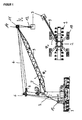
- FIG. 1 shows an embodiment of a crane according to the invention, in which an embodiment of a system according to the invention for detecting the load mass of the crane rope hanging load is used.
- the crane in the exemplary embodiment is a mobile harbor crane.
- the crane has an undercarriage 1 with a chassis 9. This allows the crane to be moved in the port. At the Hubort the crane can then be supported on support units 10.
- a tower 2 On the undercarriage 1, a tower 2 is arranged rotatably about a vertical axis of rotation. On the tower 2, a boom 5 is articulated about a horizontal axis. The boom 5 can be pivoted about the hydraulic cylinder 7 in the rocker plane up and down.
- the crane has a hoist rope 4, which is guided around a deflection roller 11 at the tip of the boom.
- a load-receiving means 12 is arranged, with which a load 3 can be accommodated.
- the load-receiving means 12 and the load 3 are thereby by moving the hoisting rope 4th raised or lowered.
- the change of the position of the load receiving means 12 and the load 3 in the vertical direction is thus carried out by reducing or increasing the length I S of the hoisting rope 4.
- a winch 13 is provided, which moves the hoist rope.
- the winch 13 is arranged on the superstructure.
- the hoist rope 4 is first guided by the winch 13 via a first deflection roller 6 at the top of the tower 2 to a deflection roller 14 at the top of the boom 5 and from there back to the tower 2, where it via a second guide roller 8 to a deflection roller 11 is guided on the jib tip, from where the hoist rope runs down to the load 3.
- the load receiving means 12 and the load can be further moved by turning the tower 2 by the angle ⁇ D and by rocking up and down the boom 5 by the angle ⁇ A in the horizontal. Due to the arrangement of the winch 13 on the superstructure, the lifting and luffing of the jib 5 results in addition to the movement of the load in the radial direction, a lifting movement of the load 3. This must optionally be compensated by a corresponding control of the winch 13.
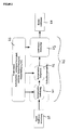
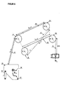
- FIG. 2 shows an embodiment of a system according to the invention for detecting the load mass of a hanging on a hoist rope of a crane load.
- the input 20 of the system is signal 20, which is generated by a measuring arrangement for measuring the cable force in the hoist rope.
- This is supplied to the calculation unit 26 according to the invention for determining the load mass.
- the calculation unit 26 supplies the exact load mass.
- the calculation unit has a compensation unit which at least partially compensates for the influences of the indirect determination of the load mass via the cable force.
- the compensation unit calculates the influences on the basis of data on the crane state, which are transmitted from the crane state unit 25 to the calculation unit 26.
- the righting or rocking angle or the upright or rocking angle speed of the boom are used in the calculation unit.
- the rope length and / or the rope speed can enter the calculation unit, wherein these are determined in particular via the position and / or speed of the hoist winch 13.
- the compensation unit is based on a physical model of the lifting system, by which the influences of the individual components of the lifting system on the cable force and the load mass can be calculated. As a result, the compensation unit can calculate these influences and at least partially compensate them.
- the compensation unit comprises three components which, however, could also be used independently of each other:
- the compensation unit initially comprises a deflection roller compensation 21 which compensates for the friction of the cable at the deflection rollers.
- the compensation unit comprises a rope mass compensation, which compensates for the influence of the rope weight on the cable force and thus on the load mass.
- the compensation unit further comprises a load mass observer 23, which takes into account dynamic disturbances of the signal due to the acceleration of the load mass or the hoist, and in particular those which arise due to the momentum of the system of hoisting rope and load.
- the cable force F S acts first on the winch and on the winch frame on the force measuring arrangement in which a force F TLC is caused by the cable force F S.
- the geometry of the arrangement of the force measuring arrangement 34 on the winch must be taken into account.
- the mass of the winch itself is to be considered, which is supported on the force measuring arrangement 34 and thus counteracts the cable force.
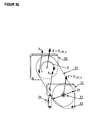
- the force measuring arrangement 34 as in FIG. 3b shown only on one of the two frame members 31 and 35 is arranged.
- the frame member 35 is firmly bolted to the crane structure. At this frame member 35, the drive for the hoist winch is arranged.
- the hoist rope 4 runs from the winch 30 via deflection rollers 6, 14 and 8 to the guide roller 11 at the tip of the boom, from where the hoist rope 4 is guided to the load 3.
- the mass of the load 3 generates a force in the hoist rope 4, which introduces the hoist rope in the winch 30.
- the winch 30 is hinged to a winch frame and acts on this with a corresponding force. This introduces a force F TLC into the force measuring assembly 34 which connects the frame member 31 of the winch frame to the crane structure. Due to the geometric relationships between hoist rope, hoist winch, winch frame and Kraftmeßan ever Thus, it is possible to deduce the mass of the load from the force measured by the force measuring arrangement 34.
- the calculation unit according to the invention therefore has a corresponding compensation unit which compensates for these influences.
- the compensation unit compensates for the influences resulting from the friction on the deflection rollers.
- the compensation unit determines the direction of rotation of the pulleys on the basis of the position and / or movement of the hoist and the boom. It must be considered that in a combined movement of the hoist and boom quite complex movement patterns of the pulleys can arise, so that not all pulleys with the same sign enter into the cable force.
- the Umlenkrollenkompensation is therefore advantageously based on the winch speed and the erection speed of the boom.
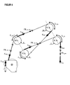
- the calculation unit according to the invention further comprises a cable mass compensation which is now based on FIG. 6 is shown in more detail.
- the weight force F W 36 of the winch must first be taken into account when calculating the cable force from the measuring signal of the measuring arrangement 34, which is supported on the Kraftmeßanssen 34.
- the hoist rope is additionally at least partially wound up.
- the mass of the hoisting rope, which is wound on the hoist winch, is thus also supported on the force measuring arrangement 34. Therefore, the weight F RW 37 of the wound on the winch hoist must be taken into account. This weight force can be determined, for example, based on the angle of rotation of the hoist winch.
- the masses of the individual cable sections between the pulleys have an influence on the cable force and thus on the determination of the load mass.
- the cable sections 41 and 42 thereby increase the measured cable force by the mass of the cable, while the cable sections 43, 44 and 45 reduce the measured cable force. In the calculation of this influence must be considered in each case the length and the angle of the cable sections to the horizontal.
- the section 41 is changed in length by raising and lowering the load.
- the sections 42-44 are in turn changed by rocking up and down the boom both in their length and in their orientation. The rope mass compensation is therefore based on the position of the boom and the hoist winch.
- the Umlenkrollenkompensation and the rope mass compensation compensate thus substantially the influence of the arrangement of the measuring arrangement on the hoist winch.
- Alternatively to the arrangement of the measuring arrangement on the hoist winch is also conceivable to integrate a measuring arrangement in one of the deflection rollers, in particular in the deflection roller 8 on the jib tip.
- the measuring arrangement the compensation is again the principles presented above, but the friction effects and the effects of the cable mass must be adapted to the measured force by the other arrangement of the measuring device accordingly.
- the system according to the invention not only takes into account the systematic influences which the arrangement of the measuring arrangement on a connecting element between Crane structure and hoisting rope on the determination of the load mass has, but also compensates for dynamic effects, which are due to the acceleration of load mass and / or hoist and the extensibility of the hoisting rope.
- the system of hoist rope and load Due to the elasticity of the hoisting rope, the system of hoist rope and load essentially forms a spring-mass pendulum, which is excited by the hoist. This creates vibrations which are superimposed on the static component of the rope force signal which corresponds to the load mass.
- the load mass observer is based on a physical model of the spring-mass system of hoisting rope and load. The model is schematically in Fig. 7 played. By comparing the cable force resulting from this model with the measured cable force, the load mass observer 23 estimates the exact load mass, which enters into the physical model as a parameter.
- illustration 1 shows the complete construction of a mobile harbor crane (LHM).
- LHM mobile harbor crane
- the load with the mass m l is lifted by the crane by means of the lifting device and is connected to the lifting hoist via the rope with the total length l s .
- the rope is deflected from the load handler via a respective deflection roller on the boom head and tower. It should be noted that the rope is not directly deflected from the boom head to the hoist winch, but that it is deflected from the boom head to the tower, back to the boom head and then over the tower to the hoist winch (see illustration 1 ).
- m max is the maximum permitted lifting capacity for each crane type.
- the load mass m l is used directly in the observer, but the normalized load mass m l m Max ,
- An incremental encoder is used to measure the winch position ⁇ w on the crane and calculate the winch speed ⁇ w .
- a force measuring sensor provides the cable force F w measured on the winch. From the winch position and speed, the rope length and speed can be calculated by means of equation (3).
- the cable force on the winch F w it should be noted that not only the force due to the load mass is measured, but also the friction influences of the pulleys and the dead weight of the rope. However, these disturbances can be eliminated by a compensation algorithm and the actual spring force F c (see equation (2)) can be calculated from the measured cable force on the winch F w .
- the input quantities u and the output quantities (or measured quantities) y of the system must first be defined.
- the rope speed i s is selected as the only system input.
- the output variables are the cable length l s and the normalized spring force F c m Max selected.
- the observer is realized as an EKF.
- k stands for the currently estimated state.
- k [•] in the following (k ⁇ t) with the discrete sampling rate ⁇ t.
- the state space representation (9) represents a continuous system, the system described above will be described below with the Euler forward method
- the EKF performs a prediction and a correction step in each time step.
- y ⁇ k - H ⁇ x ⁇ k - ⁇ u k ,
- P k- 1 is the error covariance matrix at time step (k-1) ⁇ t
- a k is the transition matrix of the linearized system around the current state
- Q k is the time-discrete covariance matrix of the system noise.
- x x ⁇ k - .
- Fig. 8 shows once again the embodiment of the load mass observer in a block diagram.
- the length of the hoist rope I S enters the load mass observer as measuring signals.
- the measured force is initially compensated as described above, first with respect to the rope weight and the friction effects and normalized with the maximum permissible load mass m max .
- the load mass observer estimates as x 4 the normalized load mass, which is accordingly converted back into the load mass ml by multiplication with m max .
- the load mass observer also estimates the cable length I s , the position of the load z and the load speed ⁇ , which can also be used for control purposes.
- the present invention enables an accurate determination of the load mass, in which both the effects of the arrangement of the measuring device for measuring the cable force via a connecting element between the crane structure and the hoist such as at a moment supported the hoist winch or a pulley, as well as dynamic effects due to the extensibility of the hoisting rope, are taken into account.
- the load mass can be used either for control tasks or for data evaluation.
- the load mass for each stroke may be stored in a memory unit, e.g. stored in a database and so evaluated.
Landscapes
- Engineering & Computer Science (AREA)
- Mechanical Engineering (AREA)
- Automation & Control Theory (AREA)
- Control And Safety Of Cranes (AREA)
- Jib Cranes (AREA)
- Force Measurement Appropriate To Specific Purposes (AREA)
Applications Claiming Priority (1)
| Application Number | Priority Date | Filing Date | Title |
|---|---|---|---|
| DE200910041662 DE102009041662A1 (de) | 2009-09-16 | 2009-09-16 | System zum Erfassen der Lastmasse einer an einem Hubseil eines Kranes hängenden Last |
Publications (3)
| Publication Number | Publication Date |
|---|---|
| EP2298687A2 true EP2298687A2 (fr) | 2011-03-23 |
| EP2298687A3 EP2298687A3 (fr) | 2013-08-21 |
| EP2298687B1 EP2298687B1 (fr) | 2016-11-30 |
Family
ID=43384415
Family Applications (1)
| Application Number | Title | Priority Date | Filing Date |
|---|---|---|---|
| EP10009567.8A Active EP2298687B1 (fr) | 2009-09-16 | 2010-09-14 | Système de détection de la masse de charge d'une charge suspendue à une corde de levage de grue |
Country Status (11)
| Country | Link |
|---|---|
| US (1) | US8949058B2 (fr) |
| EP (1) | EP2298687B1 (fr) |
| JP (1) | JP5933915B2 (fr) |
| KR (1) | KR20110030398A (fr) |
| CN (1) | CN102020199B (fr) |
| AU (1) | AU2010219433B2 (fr) |
| BR (1) | BRPI1010334A2 (fr) |
| CA (1) | CA2714913C (fr) |
| DE (1) | DE102009041662A1 (fr) |
| ES (1) | ES2617505T3 (fr) |
| RU (1) | RU2537728C2 (fr) |
Cited By (1)
| Publication number | Priority date | Publication date | Assignee | Title |
|---|---|---|---|---|
| WO2016009040A1 (fr) * | 2014-07-17 | 2016-01-21 | Terex Mhps Gmbh | Commande du degré de remplissage d'une benne preneuse d'un produit en vrac d'une grue |
Families Citing this family (28)
| Publication number | Priority date | Publication date | Assignee | Title |
|---|---|---|---|---|
| ES2447018T3 (es) * | 2011-08-26 | 2014-03-11 | Liebherr-Werk Nenzing Gmbh | Aparato de control de grúa |
| CN103814279B (zh) * | 2011-09-20 | 2016-06-29 | 株式会社石田 | 质量测量装置 |
| CN102390781B (zh) * | 2011-11-14 | 2014-07-09 | 三一汽车起重机械有限公司 | 一种用于起重机的侧向载荷保护装置及方法 |
| DE102012004803A1 (de) * | 2012-03-09 | 2013-09-12 | Liebherr-Werk Nenzing Gmbh | Kransteuerung mit Antriebsbeschränkung |
| AU2013267148B9 (en) * | 2012-06-01 | 2017-04-06 | Seatrax, Inc. | System and method to determine relative velocity of crane and target load |
| FI124888B (fi) * | 2013-06-04 | 2015-03-13 | Ponsse Oyj | Menetelmä ja järjestely punnitusjärjestelmässä sekä vastaava ohjelmistotuote ja materiaalinkäsittelykone |
| KR102040335B1 (ko) * | 2013-12-24 | 2019-11-04 | 두산인프라코어 주식회사 | 건설 기계의 적재물 무게 측정 장치 및 그 방법 |
| CN104150359B (zh) * | 2014-07-08 | 2016-06-08 | 湖南中联重科智能技术有限公司 | 起重量测量方法、设备、系统以及工程机械 |
| CN105438983B (zh) * | 2014-07-28 | 2017-05-24 | 徐州重型机械有限公司 | 一种工程机械及其卷扬乱绳监测装置和方法 |
| EP3378694B1 (fr) * | 2017-03-23 | 2019-08-14 | Vestel Elektronik Sanayi ve Ticaret A.S. | Appareil et procédé pour fournir une mesure de la capacité de courant |
| EP3461783B1 (fr) * | 2017-09-29 | 2019-11-13 | B&R Industrial Automation GmbH | Équipement de levage et procédé de commande d'un équipement de levage |
| CN108116989B (zh) * | 2017-11-03 | 2019-11-15 | 武汉船用机械有限责任公司 | 一种起重机控制方法及系统 |
| JP7059605B2 (ja) * | 2017-12-08 | 2022-04-26 | 富士電機株式会社 | クレーンの運転制御装置 |
| DE102017130792A1 (de) * | 2017-12-20 | 2019-06-27 | Liebherr-Werk Ehingen Gmbh | Messeinrichtung zur Lastmessung bei einem Hebezeug |
| GB201800250D0 (en) | 2018-01-08 | 2018-02-21 | Element Six Gmbh | Drill bit with wearshield |
| CN109977608B (zh) * | 2019-04-16 | 2023-02-28 | 兖州煤业股份有限公司 | 一种基于扳起架的起重方法和装置 |
| EP4045451B1 (fr) * | 2019-10-17 | 2025-12-24 | Terex Australia Pty Ltd | Procédé d'opération de grue mobile |
| CN110759281B (zh) * | 2019-10-31 | 2021-04-27 | 三一海洋重工有限公司 | 伸缩臂结构的称重方法及其结构、设备、存储介质 |
| CN111753435A (zh) * | 2020-07-04 | 2020-10-09 | 四川公路桥梁建设集团有限公司 | 基于分段悬链线和索力连续算法的缆索吊装系统计算方法 |
| CN112065358B (zh) * | 2020-09-17 | 2023-07-18 | 北京三一智造科技有限公司 | 钻斗状态提示方法及装置、旋挖钻机及其抖土控制方法 |
| CN112607596B (zh) * | 2020-12-16 | 2023-05-09 | 中联恒通机械有限公司 | 一种抑制汽车起重机吊钩晃动的方法及装置 |
| EP4247746A1 (fr) | 2021-01-27 | 2023-09-27 | Liebherr-Werk Biberach GmbH | Engrenage de levage et procédé de détermination de câble lâche sur l'engrenage de levage |
| DE102021103934A1 (de) | 2021-01-27 | 2022-07-28 | Liebherr-Werk Biberach Gmbh | Hebezeug sowie Verfahren zum Bestimmen von Schlaffseil an dem Hebezeug |
| DE102021124757A1 (de) * | 2021-09-24 | 2023-03-30 | Liebherr-Werk Biberach Gmbh | Kran |
| CN114722460B (zh) * | 2022-03-16 | 2025-07-29 | 中铁建城建交通发展有限公司 | 绞磨选用方法、装置、设备及存储介质 |
| CN116296517B (zh) * | 2023-05-08 | 2023-07-25 | 四川经准特种设备检验有限公司 | 一种起重机械综合性能检测装置及检测方法 |
| CN116573557B (zh) * | 2023-05-25 | 2024-03-19 | 南京工业大学 | 一种塔式起重机振幅饱和非线性输出反馈控制方法及系统 |
| DE102024118915A1 (de) * | 2024-07-03 | 2026-01-08 | Liebherr-Werk Nenzing Gmbh | Hebevorrichtung, insbesondere Kran, und Verfahren zum Betreiben einer solchen Hebevorrichtung |
Family Cites Families (11)
| Publication number | Priority date | Publication date | Assignee | Title |
|---|---|---|---|---|
| JPS5832435U (ja) * | 1981-08-28 | 1983-03-03 | 石川島播磨重工業株式会社 | 荷重検出装置 |
| JPS59170594U (ja) * | 1983-04-28 | 1984-11-14 | 住友重機械工業株式会社 | ロープ巻上装置に於けるヒステリシス補正装置を有する荷重検出器 |
| JPS59176883U (ja) * | 1983-05-12 | 1984-11-26 | 石川島播磨重工業株式会社 | クレ−ンの安全装置 |
| SU1142738A1 (ru) * | 1983-09-02 | 1985-02-28 | Киевское Производственное Объединение "Веда" | Устройство дл взвешивани в услови х колебани груза |
| DD222577A1 (de) * | 1984-03-27 | 1985-05-22 | Seefahrt Inghochschule | Elektronische kranwaage |
| JPS6232086U (fr) * | 1985-08-12 | 1987-02-25 | ||
| US4677579A (en) * | 1985-09-25 | 1987-06-30 | Becor Western Inc. | Suspended load measurement system |
| DE19512103C2 (de) * | 1995-04-03 | 1997-06-05 | Rotzler Gmbh Co | Seilwinde mit Betriebsdatenerfassung |
| JP2001039670A (ja) * | 1999-07-30 | 2001-02-13 | Sumitomo Constr Mach Co Ltd | クレ−ンの吊り荷重算出装置 |
| US6527130B2 (en) * | 2001-02-16 | 2003-03-04 | General Electric Co. | Method and system for load measurement in a crane hoist |
| DE102004027106A1 (de) * | 2004-06-03 | 2005-12-29 | Demag Cranes & Components Gmbh | Hebezeug mit Hublastmesseinrichtung |
-
2009
- 2009-09-16 DE DE200910041662 patent/DE102009041662A1/de not_active Ceased
-
2010
- 2010-09-14 ES ES10009567.8T patent/ES2617505T3/es active Active
- 2010-09-14 EP EP10009567.8A patent/EP2298687B1/fr active Active
- 2010-09-14 AU AU2010219433A patent/AU2010219433B2/en not_active Ceased
- 2010-09-14 CA CA2714913A patent/CA2714913C/fr active Active
- 2010-09-15 RU RU2010138232/28A patent/RU2537728C2/ru active
- 2010-09-15 US US12/882,960 patent/US8949058B2/en active Active
- 2010-09-16 CN CN201010289055.0A patent/CN102020199B/zh not_active Expired - Fee Related
- 2010-09-16 JP JP2010208470A patent/JP5933915B2/ja active Active
- 2010-09-16 BR BRPI1010334 patent/BRPI1010334A2/pt not_active Application Discontinuation
- 2010-09-16 KR KR1020100091020A patent/KR20110030398A/ko not_active Ceased
Non-Patent Citations (1)
| Title |
|---|
| None |
Cited By (2)
| Publication number | Priority date | Publication date | Assignee | Title |
|---|---|---|---|---|
| WO2016009040A1 (fr) * | 2014-07-17 | 2016-01-21 | Terex Mhps Gmbh | Commande du degré de remplissage d'une benne preneuse d'un produit en vrac d'une grue |
| US10611606B2 (en) | 2014-07-17 | 2020-04-07 | Konecranes Global Corporation | Fill degree control for a bulk material gripper of a crane |
Also Published As
| Publication number | Publication date |
|---|---|
| JP5933915B2 (ja) | 2016-06-15 |
| BRPI1010334A2 (pt) | 2012-12-18 |
| CA2714913A1 (fr) | 2011-03-16 |
| CA2714913C (fr) | 2017-10-24 |
| EP2298687B1 (fr) | 2016-11-30 |
| RU2537728C2 (ru) | 2015-01-10 |
| KR20110030398A (ko) | 2011-03-23 |
| CN102020199B (zh) | 2015-08-05 |
| JP2011079674A (ja) | 2011-04-21 |
| CN102020199A (zh) | 2011-04-20 |
| ES2617505T3 (es) | 2017-06-19 |
| AU2010219433A1 (en) | 2011-03-31 |
| US8949058B2 (en) | 2015-02-03 |
| EP2298687A3 (fr) | 2013-08-21 |
| DE102009041662A1 (de) | 2011-03-24 |
| AU2010219433B2 (en) | 2015-07-09 |
| RU2010138232A (ru) | 2012-03-20 |
| US20110066394A1 (en) | 2011-03-17 |
Similar Documents
| Publication | Publication Date | Title |
|---|---|---|
| EP2298687B1 (fr) | Système de détection de la masse de charge d'une charge suspendue à une corde de levage de grue | |
| EP3784616B1 (fr) | Grue et procédé pour commander une grue de ce type | |
| EP2272786B1 (fr) | Commande de grue pour la commande d'un dispositif de levage de grue | |
| EP3649072B1 (fr) | Grue et procédé de commande d'une telle grue | |
| EP4013713B1 (fr) | Grue et procédé de commande d'une telle grue | |
| EP2502871B1 (fr) | Commande de grue, grue et procédé | |
| EP2272785B1 (fr) | Procédé de commande d'un entraînement de grue | |
| EP3408208B1 (fr) | Grue et procédé de commande de ladite grue | |
| EP2636635B1 (fr) | Commande de grue avec mode de traction de câble | |
| EP2524892B1 (fr) | Commande de grue | |
| EP2878566B1 (fr) | Procédé d'influence d'un mouvement d'une charge logée au niveau d'une grue | |
| AT520008B1 (de) | Verfahren zum Dämpfen von Drehschwingungen eines Lastaufnahmeelements einer Hebeeinrichtung | |
| DE102007041692A1 (de) | Regelungseinrichtung zur Dämpfung von Pendelbewegungen einer seilgeführten Last | |
| EP2947035A1 (fr) | Procédé de détermination de la charge d'une machine de travail et machine de travail, en particulier une grue | |
| DE102005042721A1 (de) | Gelenkleiter oder Hubbühne mit Bahnsteuerung und aktiver Schwingungsdämpfung | |
| DE10029579A1 (de) | Verfahren zur Orientierung der Last in Krananlagen | |
| EP4707217A2 (fr) | Grue à tour, procédé et unité de commande pour faire fonctionner une grue à tour, chariot et train d'atterrissage | |
| EP4406905A1 (fr) | Procédé et dispositif de fonctionnement d'une grue à flèche rotative et grue à flèche rotative | |
| EP2878567A1 (fr) | Procédé de détermination d'au moins un angle d'oscillation d'une charge absorbée par un dispositif de transport de charges et procédé d'amortissement de mouvements d'oscillation de la charge | |
| WO2019121990A1 (fr) | Dispositif de mesure permettant de mesurer une charge dans un engin de levage | |
| DE10230469B4 (de) | Vorrichtung zum Überwachen der Zulässigkeit der augenblicklichen Belastung einer Hubeinrichtung | |
| EP3326957A1 (fr) | Procédé de fonctionnement d'une grue | |
| DE202023002939U1 (de) | Vorrichtung zum Betreiben eines Auslegerdrehkrans sowie Auslegerdrehkran |
Legal Events
| Date | Code | Title | Description |
|---|---|---|---|
| PUAI | Public reference made under article 153(3) epc to a published international application that has entered the european phase |
Free format text: ORIGINAL CODE: 0009012 |
|
| AK | Designated contracting states |
Kind code of ref document: A2 Designated state(s): AL AT BE BG CH CY CZ DE DK EE ES FI FR GB GR HR HU IE IS IT LI LT LU LV MC MK MT NL NO PL PT RO SE SI SK SM TR |
|
| AX | Request for extension of the european patent |
Extension state: BA ME RS |
|
| PUAL | Search report despatched |
Free format text: ORIGINAL CODE: 0009013 |
|
| AK | Designated contracting states |
Kind code of ref document: A3 Designated state(s): AL AT BE BG CH CY CZ DE DK EE ES FI FR GB GR HR HU IE IS IT LI LT LU LV MC MK MT NL NO PL PT RO SE SI SK SM TR |
|
| AX | Request for extension of the european patent |
Extension state: BA ME RS |
|
| RIC1 | Information provided on ipc code assigned before grant |
Ipc: B66C 13/16 20060101AFI20130716BHEP |
|
| 17P | Request for examination filed |
Effective date: 20140221 |
|
| 17Q | First examination report despatched |
Effective date: 20140428 |
|
| GRAP | Despatch of communication of intention to grant a patent |
Free format text: ORIGINAL CODE: EPIDOSNIGR1 |
|
| INTG | Intention to grant announced |
Effective date: 20160627 |
|
| GRAS | Grant fee paid |
Free format text: ORIGINAL CODE: EPIDOSNIGR3 |
|
| GRAA | (expected) grant |
Free format text: ORIGINAL CODE: 0009210 |
|
| AK | Designated contracting states |
Kind code of ref document: B1 Designated state(s): AL AT BE BG CH CY CZ DE DK EE ES FI FR GB GR HR HU IE IS IT LI LT LU LV MC MK MT NL NO PL PT RO SE SI SK SM TR |
|
| REG | Reference to a national code |
Ref country code: CH Ref legal event code: EP Ref country code: GB Ref legal event code: FG4D Free format text: NOT ENGLISH |
|
| REG | Reference to a national code |
Ref country code: AT Ref legal event code: REF Ref document number: 849591 Country of ref document: AT Kind code of ref document: T Effective date: 20161215 |
|
| REG | Reference to a national code |
Ref country code: IE Ref legal event code: FG4D Free format text: LANGUAGE OF EP DOCUMENT: GERMAN |
|
| REG | Reference to a national code |
Ref country code: DE Ref legal event code: R096 Ref document number: 502010012794 Country of ref document: DE |
|
| PG25 | Lapsed in a contracting state [announced via postgrant information from national office to epo] |
Ref country code: LV Free format text: LAPSE BECAUSE OF FAILURE TO SUBMIT A TRANSLATION OF THE DESCRIPTION OR TO PAY THE FEE WITHIN THE PRESCRIBED TIME-LIMIT Effective date: 20161130 |
|
| REG | Reference to a national code |
Ref country code: LT Ref legal event code: MG4D |
|
| REG | Reference to a national code |
Ref country code: NL Ref legal event code: MP Effective date: 20161130 |
|
| PG25 | Lapsed in a contracting state [announced via postgrant information from national office to epo] |
Ref country code: LT Free format text: LAPSE BECAUSE OF FAILURE TO SUBMIT A TRANSLATION OF THE DESCRIPTION OR TO PAY THE FEE WITHIN THE PRESCRIBED TIME-LIMIT Effective date: 20161130 Ref country code: GR Free format text: LAPSE BECAUSE OF FAILURE TO SUBMIT A TRANSLATION OF THE DESCRIPTION OR TO PAY THE FEE WITHIN THE PRESCRIBED TIME-LIMIT Effective date: 20170301 Ref country code: NO Free format text: LAPSE BECAUSE OF FAILURE TO SUBMIT A TRANSLATION OF THE DESCRIPTION OR TO PAY THE FEE WITHIN THE PRESCRIBED TIME-LIMIT Effective date: 20170228 Ref country code: SE Free format text: LAPSE BECAUSE OF FAILURE TO SUBMIT A TRANSLATION OF THE DESCRIPTION OR TO PAY THE FEE WITHIN THE PRESCRIBED TIME-LIMIT Effective date: 20161130 |
|
| PG25 | Lapsed in a contracting state [announced via postgrant information from national office to epo] |
Ref country code: HR Free format text: LAPSE BECAUSE OF FAILURE TO SUBMIT A TRANSLATION OF THE DESCRIPTION OR TO PAY THE FEE WITHIN THE PRESCRIBED TIME-LIMIT Effective date: 20161130 Ref country code: FI Free format text: LAPSE BECAUSE OF FAILURE TO SUBMIT A TRANSLATION OF THE DESCRIPTION OR TO PAY THE FEE WITHIN THE PRESCRIBED TIME-LIMIT Effective date: 20161130 Ref country code: PL Free format text: LAPSE BECAUSE OF FAILURE TO SUBMIT A TRANSLATION OF THE DESCRIPTION OR TO PAY THE FEE WITHIN THE PRESCRIBED TIME-LIMIT Effective date: 20161130 Ref country code: PT Free format text: LAPSE BECAUSE OF FAILURE TO SUBMIT A TRANSLATION OF THE DESCRIPTION OR TO PAY THE FEE WITHIN THE PRESCRIBED TIME-LIMIT Effective date: 20170330 |
|
| REG | Reference to a national code |
Ref country code: ES Ref legal event code: FG2A Ref document number: 2617505 Country of ref document: ES Kind code of ref document: T3 Effective date: 20170619 |
|
| PG25 | Lapsed in a contracting state [announced via postgrant information from national office to epo] |
Ref country code: NL Free format text: LAPSE BECAUSE OF FAILURE TO SUBMIT A TRANSLATION OF THE DESCRIPTION OR TO PAY THE FEE WITHIN THE PRESCRIBED TIME-LIMIT Effective date: 20161130 |
|
| PG25 | Lapsed in a contracting state [announced via postgrant information from national office to epo] |
Ref country code: DK Free format text: LAPSE BECAUSE OF FAILURE TO SUBMIT A TRANSLATION OF THE DESCRIPTION OR TO PAY THE FEE WITHIN THE PRESCRIBED TIME-LIMIT Effective date: 20161130 Ref country code: CZ Free format text: LAPSE BECAUSE OF FAILURE TO SUBMIT A TRANSLATION OF THE DESCRIPTION OR TO PAY THE FEE WITHIN THE PRESCRIBED TIME-LIMIT Effective date: 20161130 Ref country code: SK Free format text: LAPSE BECAUSE OF FAILURE TO SUBMIT A TRANSLATION OF THE DESCRIPTION OR TO PAY THE FEE WITHIN THE PRESCRIBED TIME-LIMIT Effective date: 20161130 Ref country code: RO Free format text: LAPSE BECAUSE OF FAILURE TO SUBMIT A TRANSLATION OF THE DESCRIPTION OR TO PAY THE FEE WITHIN THE PRESCRIBED TIME-LIMIT Effective date: 20161130 Ref country code: EE Free format text: LAPSE BECAUSE OF FAILURE TO SUBMIT A TRANSLATION OF THE DESCRIPTION OR TO PAY THE FEE WITHIN THE PRESCRIBED TIME-LIMIT Effective date: 20161130 |
|
| PG25 | Lapsed in a contracting state [announced via postgrant information from national office to epo] |
Ref country code: BG Free format text: LAPSE BECAUSE OF FAILURE TO SUBMIT A TRANSLATION OF THE DESCRIPTION OR TO PAY THE FEE WITHIN THE PRESCRIBED TIME-LIMIT Effective date: 20170228 Ref country code: SM Free format text: LAPSE BECAUSE OF FAILURE TO SUBMIT A TRANSLATION OF THE DESCRIPTION OR TO PAY THE FEE WITHIN THE PRESCRIBED TIME-LIMIT Effective date: 20161130 |
|
| REG | Reference to a national code |
Ref country code: DE Ref legal event code: R097 Ref document number: 502010012794 Country of ref document: DE |
|
| REG | Reference to a national code |
Ref country code: FR Ref legal event code: PLFP Year of fee payment: 8 |
|
| PLBE | No opposition filed within time limit |
Free format text: ORIGINAL CODE: 0009261 |
|
| STAA | Information on the status of an ep patent application or granted ep patent |
Free format text: STATUS: NO OPPOSITION FILED WITHIN TIME LIMIT |
|
| 26N | No opposition filed |
Effective date: 20170831 |
|
| PG25 | Lapsed in a contracting state [announced via postgrant information from national office to epo] |
Ref country code: SI Free format text: LAPSE BECAUSE OF FAILURE TO SUBMIT A TRANSLATION OF THE DESCRIPTION OR TO PAY THE FEE WITHIN THE PRESCRIBED TIME-LIMIT Effective date: 20161130 |
|
| REG | Reference to a national code |
Ref country code: CH Ref legal event code: PL |
|
| GBPC | Gb: european patent ceased through non-payment of renewal fee |
Effective date: 20170914 |
|
| PG25 | Lapsed in a contracting state [announced via postgrant information from national office to epo] |
Ref country code: MC Free format text: LAPSE BECAUSE OF FAILURE TO SUBMIT A TRANSLATION OF THE DESCRIPTION OR TO PAY THE FEE WITHIN THE PRESCRIBED TIME-LIMIT Effective date: 20161130 |
|
| REG | Reference to a national code |
Ref country code: IE Ref legal event code: MM4A |
|
| REG | Reference to a national code |
Ref country code: BE Ref legal event code: MM Effective date: 20170930 |
|
| PG25 | Lapsed in a contracting state [announced via postgrant information from national office to epo] |
Ref country code: LU Free format text: LAPSE BECAUSE OF NON-PAYMENT OF DUE FEES Effective date: 20170914 |
|
| PG25 | Lapsed in a contracting state [announced via postgrant information from national office to epo] |
Ref country code: LI Free format text: LAPSE BECAUSE OF NON-PAYMENT OF DUE FEES Effective date: 20170930 Ref country code: GB Free format text: LAPSE BECAUSE OF NON-PAYMENT OF DUE FEES Effective date: 20170914 Ref country code: CH Free format text: LAPSE BECAUSE OF NON-PAYMENT OF DUE FEES Effective date: 20170930 Ref country code: IE Free format text: LAPSE BECAUSE OF NON-PAYMENT OF DUE FEES Effective date: 20170914 |
|
| PG25 | Lapsed in a contracting state [announced via postgrant information from national office to epo] |
Ref country code: BE Free format text: LAPSE BECAUSE OF NON-PAYMENT OF DUE FEES Effective date: 20170930 |
|
| REG | Reference to a national code |
Ref country code: FR Ref legal event code: PLFP Year of fee payment: 9 |
|
| PG25 | Lapsed in a contracting state [announced via postgrant information from national office to epo] |
Ref country code: MT Free format text: LAPSE BECAUSE OF FAILURE TO SUBMIT A TRANSLATION OF THE DESCRIPTION OR TO PAY THE FEE WITHIN THE PRESCRIBED TIME-LIMIT Effective date: 20161130 |
|
| REG | Reference to a national code |
Ref country code: AT Ref legal event code: MM01 Ref document number: 849591 Country of ref document: AT Kind code of ref document: T Effective date: 20170914 |
|
| PG25 | Lapsed in a contracting state [announced via postgrant information from national office to epo] |
Ref country code: AT Free format text: LAPSE BECAUSE OF NON-PAYMENT OF DUE FEES Effective date: 20170914 |
|
| PG25 | Lapsed in a contracting state [announced via postgrant information from national office to epo] |
Ref country code: HU Free format text: LAPSE BECAUSE OF FAILURE TO SUBMIT A TRANSLATION OF THE DESCRIPTION OR TO PAY THE FEE WITHIN THE PRESCRIBED TIME-LIMIT; INVALID AB INITIO Effective date: 20100914 |
|
| PG25 | Lapsed in a contracting state [announced via postgrant information from national office to epo] |
Ref country code: CY Free format text: LAPSE BECAUSE OF NON-PAYMENT OF DUE FEES Effective date: 20161130 |
|
| PG25 | Lapsed in a contracting state [announced via postgrant information from national office to epo] |
Ref country code: MK Free format text: LAPSE BECAUSE OF FAILURE TO SUBMIT A TRANSLATION OF THE DESCRIPTION OR TO PAY THE FEE WITHIN THE PRESCRIBED TIME-LIMIT Effective date: 20161130 |
|
| PG25 | Lapsed in a contracting state [announced via postgrant information from national office to epo] |
Ref country code: TR Free format text: LAPSE BECAUSE OF FAILURE TO SUBMIT A TRANSLATION OF THE DESCRIPTION OR TO PAY THE FEE WITHIN THE PRESCRIBED TIME-LIMIT Effective date: 20161130 |
|
| PG25 | Lapsed in a contracting state [announced via postgrant information from national office to epo] |
Ref country code: AL Free format text: LAPSE BECAUSE OF FAILURE TO SUBMIT A TRANSLATION OF THE DESCRIPTION OR TO PAY THE FEE WITHIN THE PRESCRIBED TIME-LIMIT Effective date: 20161130 Ref country code: IS Free format text: LAPSE BECAUSE OF FAILURE TO SUBMIT A TRANSLATION OF THE DESCRIPTION OR TO PAY THE FEE WITHIN THE PRESCRIBED TIME-LIMIT Effective date: 20170330 |
|
| PGFP | Annual fee paid to national office [announced via postgrant information from national office to epo] |
Ref country code: IT Payment date: 20220930 Year of fee payment: 13 Ref country code: ES Payment date: 20221003 Year of fee payment: 13 |
|
| P01 | Opt-out of the competence of the unified patent court (upc) registered |
Effective date: 20230630 |
|
| PGFP | Annual fee paid to national office [announced via postgrant information from national office to epo] |
Ref country code: FR Payment date: 20240924 Year of fee payment: 15 |
|
| REG | Reference to a national code |
Ref country code: ES Ref legal event code: FD2A Effective date: 20241029 |
|
| PG25 | Lapsed in a contracting state [announced via postgrant information from national office to epo] |
Ref country code: IT Free format text: LAPSE BECAUSE OF NON-PAYMENT OF DUE FEES Effective date: 20230914 |
|
| PG25 | Lapsed in a contracting state [announced via postgrant information from national office to epo] |
Ref country code: IT Free format text: LAPSE BECAUSE OF NON-PAYMENT OF DUE FEES Effective date: 20230914 |
|
| PG25 | Lapsed in a contracting state [announced via postgrant information from national office to epo] |
Ref country code: ES Free format text: LAPSE BECAUSE OF NON-PAYMENT OF DUE FEES Effective date: 20230915 |
|
| PG25 | Lapsed in a contracting state [announced via postgrant information from national office to epo] |
Ref country code: ES Free format text: LAPSE BECAUSE OF NON-PAYMENT OF DUE FEES Effective date: 20230915 |
|
| PGFP | Annual fee paid to national office [announced via postgrant information from national office to epo] |
Ref country code: DE Payment date: 20251002 Year of fee payment: 16 |