EP2307629B1 - Paroi de séparation constituée d'éléments de paroi transparents - Google Patents
Paroi de séparation constituée d'éléments de paroi transparents Download PDFInfo
- Publication number
- EP2307629B1 EP2307629B1 EP09761402.8A EP09761402A EP2307629B1 EP 2307629 B1 EP2307629 B1 EP 2307629B1 EP 09761402 A EP09761402 A EP 09761402A EP 2307629 B1 EP2307629 B1 EP 2307629B1
- Authority
- EP
- European Patent Office
- Prior art keywords
- elements
- pane
- profile frame
- wall
- wall according
- Prior art date
- Legal status (The legal status is an assumption and is not a legal conclusion. Google has not performed a legal analysis and makes no representation as to the accuracy of the status listed.)
- Active
Links
Images

Classifications
-
- E—FIXED CONSTRUCTIONS
- E04—BUILDING
- E04B—GENERAL BUILDING CONSTRUCTIONS; WALLS, e.g. PARTITIONS; ROOFS; FLOORS; CEILINGS; INSULATION OR OTHER PROTECTION OF BUILDINGS
- E04B2/00—Walls, e.g. partitions, for buildings; Wall construction with regard to insulation; Connections specially adapted to walls
- E04B2/74—Removable non-load-bearing partitions; Partitions with a free upper edge
- E04B2/82—Removable non-load-bearing partitions; Partitions with a free upper edge characterised by the manner in which edges are connected to the building; Means therefor; Special details of easily-removable partitions as far as related to the connection with other parts of the building
- E04B2/827—Partitions constituted of sliding panels
-
- E—FIXED CONSTRUCTIONS
- E06—DOORS, WINDOWS, SHUTTERS, OR ROLLER BLINDS IN GENERAL; LADDERS
- E06B—FIXED OR MOVABLE CLOSURES FOR OPENINGS IN BUILDINGS, VEHICLES, FENCES OR LIKE ENCLOSURES IN GENERAL, e.g. DOORS, WINDOWS, BLINDS, GATES
- E06B3/00—Window sashes, door leaves, or like elements for closing wall or like openings; Layout of fixed or moving closures, e.g. windows in wall or like openings; Features of rigidly-mounted outer frames relating to the mounting of wing frames
- E06B3/02—Wings made completely of glass
- E06B3/025—Wings made completely of glass consisting of multiple glazing units
-
- E—FIXED CONSTRUCTIONS
- E06—DOORS, WINDOWS, SHUTTERS, OR ROLLER BLINDS IN GENERAL; LADDERS
- E06B—FIXED OR MOVABLE CLOSURES FOR OPENINGS IN BUILDINGS, VEHICLES, FENCES OR LIKE ENCLOSURES IN GENERAL, e.g. DOORS, WINDOWS, BLINDS, GATES
- E06B3/00—Window sashes, door leaves, or like elements for closing wall or like openings; Layout of fixed or moving closures, e.g. windows in wall or like openings; Features of rigidly-mounted outer frames relating to the mounting of wing frames
- E06B3/32—Arrangements of wings characterised by the manner of movement; Arrangements of movable wings in openings; Features of wings or frames relating solely to the manner of movement of the wing
- E06B3/34—Arrangements of wings characterised by the manner of movement; Arrangements of movable wings in openings; Features of wings or frames relating solely to the manner of movement of the wing with only one kind of movement
- E06B3/42—Sliding wings; Details of frames with respect to guiding
- E06B3/46—Horizontally-sliding wings
- E06B3/4609—Horizontally-sliding wings for windows
Definitions
- the present invention relates to a partition with a plurality of wall elements, which are movably received via a guide means.
- the lateral planar surfaces of the wall elements are formed by transparent disc elements to provide a transparent mobile partition of several wall elements.
- Such wall elements for forming a mobile partition with transparent pane elements are used in rooms such as shops to form a mobile window front, in shops for variable separation of customer areas, in public buildings and in particular in banks, in which after closing an inner part of the customer area of an outer Part is separated.
- the transparent disc elements have fittings on which guide means are mounted to receive the wall elements, for example in a ceiling rail system and to lead in this. Often, the disc elements are arranged individually and form the body of the wall element itself. The fittings are then placed on the top and bottom of the disc element so that when several wall elements are juxtaposed to form the dividing wall, the disc elements are made of glass directly adjoin one another.
- partitions with a plurality of glass elements which are constructed of transparent disc elements, have the disadvantage that no sound insulation is possible because the disc elements on the one hand only simple and not double-walled and on the other hand have no seal in the edge region of the disc elements.
- wall elements are known for the formation of partitions which have sound insulation means, but such devices are not known for wall elements consisting of transparent disk elements. The problem already arises from the integration of a sound insulation device in the fittings, which border the disk element at least on the upper side and on the lower side.
- partitions with a plurality of wall elements are known, wherein the wall elements have a frame structure, are used in the tailored panels, which consist of MDF panels, solid wood panels or plastic sheets.
- Such wall elements have sound insulation means to provide a soundproof mobile partition.
- Wall elements are also known with windows, which are introduced in the form of a cutout within the side plates in this. The window section inside the side plates does not interfere with the integration of the sound insulation device, which usually takes up a considerable amount of space and is based on a spindle system, are moved by the sealing elements both against the ground and against the ceiling of the room.
- the DE 29822256 U1 shows a mobile glass partition wall according to the preamble of claim 1, in which a largely automatic extension of the sealing strips is made possible via pneumatic actuated lifting elements when the sliding elements move together.
- This glass partition can not achieve the required sound levels, since the glass sheets are arranged in a too small distance in the profile.
- the partition according to the invention has a plurality of wall elements, which are movably received via a guide device, wherein the wall elements has two spaced apart at a distance transparent disc elements, and wherein the wall elements have a profile frame for receiving the disc elements and in which further a sound insulation device is accommodated, to sound-insulating the wall elements at least against a floor and against a ceiling.
- the partition according to the invention combines the properties of a transparent partition with the advantages of sound insulation. Only through the inventive recording of the disc elements in a profile frame, the requirement is created to integrate a sound insulation device in the wall elements.
- the sound insulation is created on the one hand by the sound-insulating sealing of the wall elements against the ground and against the ceiling of the room, on the other hand, the plane-parallel arrangement of two transparent disc elements contributes to each other at a distance to the sound insulation. This is made possible only by the profile frame, which forms the wall element in combination of the transparent disc elements. Due to the given distance of the two transparent disc elements to each other, the effect of the sound insulation is enhanced, with a greater distance between the disk elements leads to better sound insulation values.
- the wall element should not exceed a given width dimension, so that it is advantageous to arrange the disk elements in the wall element as possible outside. Consequently, the profile frame should not protrude significantly beyond the outer surfaces of the disc elements.
- the distance between the two glass panes received in the profile frame has a value of at least 80 mm, wherein the wall element does not exceed a total thickness of 100 mm.
- the side surfaces of the wall element are predominantly formed by the disk elements, wherein the profile frame surrounds the disk elements only at the edge and encloses them.
- the wall element according to the invention has only one profile frame, which is made so narrow that it only appears on the edge side, and the disc elements are enclosed in the profile frame.
- the ratio between the side surface formed by the profile frame compared to the side surface formed by the disk element can be compared with a window sash of a building. In the case of a window sash, a window frame merely grips the window pane at the edge, without the window frame forming a significant part of the side surface of the window.
- the disk elements are formed from glass sheets, wherein preferably at least one of the two disk elements may comprise a single glass pane or a double glass pane.
- the partition according to the invention has the function of thermal insulation.
- the profile frame can also have a thermal separation, in which this example has both an inside and an outside aluminum profile, which are held together on plastic webs inside. This creates a barrier against a heat flow from a warm to a cold side, which are separated by the partition wall. It may be sufficient to carry out at least one of the two disk elements as a double glass pane, wherein the second glass pane may be a single glass pane.
- the glass sheets are also possible to form the glass sheets as single glass panes and to combine either with the same or with a different thickness.
- the combination of different glass pane thicknesses leads to lower resonance effects, which in turn can further enhance the sound insulation.
- a possible embodiment of the profile frame has vertically extending side frame parts, which are combined in the manner of a tongue and groove connection such that a plurality of wall elements arranged side by side can be and form a form fit.
- a wall member has a first vertically extending side frame portion on a first side that includes a groove, the opposing second vertically extending frame portion on the second side having a spring geometry.
- sealing elements can be provided to improve the sound insulation.
- the profile frame consists on the upper side of a horizontally extending upper spar and on the bottom side on a horizontally extending lower beam. As a result, a mostly rectangular profile frame is formed, wherein the vertically extending side frame parts are connected to the respective upper and lower rails.
- connection can be made by angle profiles, which can be made of a stronger material, such as a steel material, since the weight of the disc elements is supported by the angle profiles, because the wall elements are usually taken with a guide device attached to the ceiling of the room is.
- Such wall elements may have heights of over four meters, so that when two glass sheets used in the profile frame of greater thickness, a considerable weight arises, which is first taken up by the lower beam and is introduced via the angle profiles in the vertically extending side frame parts.
- the partition wall on a sound insulation device which is arranged in the upper beam and / or in the lower beam.
- the sound insulation device has sealing elements, which are each movable from the upper beam against the ceiling and from the lower beam against the ground.
- the sealing elements must be arranged movable in the upper and lower spar, since the sealing elements are moved only after reaching the final position of the wall element in the partition wall against the ceiling and the floor. Consequently, the wall element can be moved within the guide device without the sealing elements sealing against the ceiling and the floor.
- a first drive unit is provided in the upper beam and a second drive unit in the lower beam which separately moves a respective sealing element against both the ceiling and the floor.
- the wall element according to the invention has separate drive units for the sealing elements for sealing against the ceiling and against the floor.
- the drive units In order to provide the inventive design of the wall element with a profile frame in which the drive units are introduced on the top and bottom, the drive units must be adapted to the available space within the upper spar and the lower spar.
- An alternative embodiment of a drive unit may comprise a spindle system which has only one drive, which is integrated in one of the vertically extending side frame parts, and cooperates both with the cover-side and with the bottom-side sealing element. Only then can the drive of the sealing elements on the upper side and underside be reduced to a drive unit. Regardless of the arrangement of the drive unit in the side frame parts or in the upper and lower beam this has been displaced at least from the middle of the wall element. Consequently, the transparency through the wall elements is not hindered by the arrangement of the drive unit.
- the profile frame is determined by a width which does not exceed a value of 200 mm, preferably a value of 150 mm and particularly preferably a value of 120 mm. Only in this way can it be ensured that the side surface of the wall element is predominantly formed by the disk element.
- the parapet height from the bottom to the top of the profile frame in the area of the sub-spar is limited to a value of 120 mm, with a small width of the profile frame contributes to a desirable, filigree appearance of the partition.
- clamping strips are provided, by means of which the disk elements are received in the profile frame.
- the clipists are arranged on the outside of the profile frame, so that both disk elements are held by the clipists by means of an elastic pressure against the profile frame.
- the clip strip on the side of the sub-spar can be made in one piece with the lower beam, so that the disc elements can first be inserted or adjusted in the lower-side clip strip. Subsequently, the clipists are used on the side frame members as well as on the upper spar to secure the disc member in the profile frame.
- the clipists which are arranged on the vertically extending side frame parts and on the upper spar, have a U-shaped extruded profile.
- the U-shaped extruded profile causes with a first U-leg a positive connection in the side frame part, and generates with a second U-leg a pressure of the disc element against the profile frame.
- This second U-leg is made longer with respect to the first U-leg and extends in sections over the disc element.
- plug-in seals are provided which cooperate with the clamping strips.
- the plug-in seals are pressed on the entire circumference of the profile frame between the second leg of the clip strip and the disc element, and can lock in the clip strip.
- the male seals may be made of a rubbery material to provide both a seal against contaminants that may get between the disc elements, as well as to allow compliance between the profile frame and the disc element, for example, to accommodate thermal expansion.
- the wall element has a total thickness of about 100 mm. This reduces the stacking height of the wall elements in a parking position. Furthermore, a smaller thickness of the wall element contributes to a filigree appearance, wherein it is also desirable to accommodate the disc elements with a large distance from each other in the profile frame. As a result, the clipists have only a small height above the disk element which is less than the thickness of the disk element so as not to unnecessarily increase the overall thickness of the wall elements.
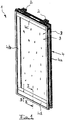
- FIG. 1 is a perspective view of a wall element 1 is shown.
- Several of these wall elements 1 can be arranged in a space adjacent to each other to form a partition wall.
- the guide device 2 has a plurality of rollers which either run only for guiding the wall element 1 in the rail system or can be driven to form an automatically movable partition.
- the wall element 1 essentially comprises two transparent disc elements 3 which are arranged at a parallel distance from each other and which are received in a profile frame 4.
- the profile frame 4 has a rectangular shape and surrounds the disc elements 3.
- the profile frame 4 forms only a small part of the side surface of the wall element 1, so that the width B of the profile frame 4 only a small proportion the lateral overall dimensions of the wall element 1 occupies.
- the profile frame 4 has two vertically extending side frame parts 4a and 4b, which are connected via an upper leg 4c on the upper side and a lower leg 4d on the lower side of the wall element 1.
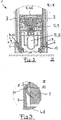
- FIG. 2 follows a cross-sectional view in the cross-sectional plane II-II, which is placed through the lower beam 4d.
- FIG. 2 shows the cross-sectional view through the wall element 1 in the region of the sub-spar 4d according to the section II-II FIG. 1 ,
- the disc elements 3 can be seen, on the left side a thin and right side a thicker disc element 3 is inserted, which in are arranged at a distance from each other.
- the distance of the disc elements 3 to each other is determined by the width of the profile frame 4.
- the disc elements 3 are accommodated as possible at a great distance from each other within a profile frame 4, which is reinforced by a cover band 10, to compensate for the smaller thickness of the disc element 3 on the left side.
- a sound insulation device 5 is integrated, which has at least one sealing element 8 which is movable by means of a drive unit 9 against a bottom 11.
- the sealing element 8 consists at least of a rubber lip, which extends in addition to other sealing elements 12 over the entire width of the wall element 1 away.
- the sealing elements 8 and 12 are received in a receiving frame 13 which is vertically movable by the drive unit 9 against the ground.
- the lower beam 4d has on the outside Clipmannn 6, which are made in one piece with the lower beam 4d.
- the clamping strips 6 have a U-shaped cross section, so that the disk elements 3 can first be inserted into the clamping strips 6. Due to the lower-side arrangements of the clamping strips 6, the disk elements 3 are held therein by their gravitational force, so that subsequently a plug-in seal 7 can be inserted between the clip strip 6 and the disk elements 3 in order to finally receive the disk element 3 in the profile frame 4.
- a detailed view of the arrangement of a plug-in seal 7 in the clip strip 6 is according to the detail III in the FIG. 3 shown in more detail.
- FIG. 3 shows a detailed view of the detail III FIG. 2 ,
- the clip strip 6 is part of the sub-spar 4 d, and has a leg which extends on the outside over the disc element 3 away.
- the clip strip 6 has a latching geometry 14, through which the plug-in seal 7 can be kept.
- This has a recess 15 into which the nose-like locking geometry 14 of the clip strip 6 can hook. Consequently, it is possible to press the plug-in seal 7 between the clip strip 6 and the disc element 3, wherein the plug-in seal 7 is shown in the undeformed state, and the deformation takes place such that the plug-in seal 7 presses against the surface of the disc element 3.
- FIGS. 4a and 4b show a cross-sectional view of the profile frame 4 in the region of the side frame parts 4a and 4b.
- FIG. 4a is a cross section of the left side arranged side frame part 4a and in the FIG. 4b a cross-sectional view of the side frame part 4b of the profile frame 4 is shown.
- the side frame part 4a is designed as a groove part, whereas the side frame part 4b forms a spring part which is intended to engage in the groove part 4a of an adjacent wall element.
- Further sealing elements 16 and 17 are arranged in the tongue and groove geometry in order to make even the joint between the wall elements themselves soundproof.
- the view also shows two disc elements 3, which are received at a distance from each other in the side frame part 4a and 4b.
- the recording takes place via clamping strips 6, which act in the same way with a plug-in seal 7, as already shown by the inclusion of the disc element 3 in the region of the sub-spar according to the FIG. 3 is described.
- the clamping strips 6 in the region of the side frame parts 4a and 4b are designed as individual parts, and have a U-shaped configuration with a short and a long U-leg.
- the short U-leg engages positively in a geometry of the side frame part 4a and 4b, so that the long U-leg extends over a portion on the disc member 3 away.
- FIG. 5 shows a detailed view of the arrangement of the clip strip 6 on the side frame profile 4a according to the detail IV FIG. 4a ,
- the disc element 3 shown here is designed to be thinner, so that in the receiving geometry of the side frame part 4 a a decorative band 10 is used to compensate for the width of the receiving recess for receiving the disc element 3.
- the connection between the plug-in seal 7 and the clip strip 6 takes place in the same way via a latching geometry 14, which is formed on the clip strip 6 and engages positively in a recess 15 which is present in the plug-in seal 7.
- the plug-in seal 7 has an elastic material such as a rubber band and the like, so that this can deform and causes a contact pressure of the disc element 3 against the cover strip 10 or against the profile frame 4 by the deformation.
- the invention is not limited in its execution to the above-mentioned preferred embodiment. Rather, a number of variants is conceivable, which makes use of the illustrated solution even with fundamentally different types of use.
- the disk elements 3 may also consist of a polarization glass in order to temporarily suspend the transparency of the disk elements with appropriate electrical wiring.
- a special gas can be introduced between the two disk elements 3, which enables improved insulation properties for sound insulation.
- the material of the profile frame 4 may be an aluminum extruded profile, which may also be made split and includes a plastic bridge to provide a thermal insulation between the two outer surfaces of the wall element 1.
Landscapes
- Engineering & Computer Science (AREA)
- Civil Engineering (AREA)
- Structural Engineering (AREA)
- Architecture (AREA)
- Physics & Mathematics (AREA)
- Electromagnetism (AREA)
- Building Environments (AREA)
- Specific Sealing Or Ventilating Devices For Doors And Windows (AREA)
- Securing Of Glass Panes Or The Like (AREA)
Claims (14)
- Paroi de séparation avec plusieurs éléments de paroi (1), lesquels sont accommodés de façon mobile par l'intermédiaire d'un dispositif de guidage (2), les éléments de paroi (1) comprenant deux éléments transparents de vitre (3) en verre agencés dans une distance parallèlement l'un à l'autre, et les éléments de paroi (1) comprenant un cadre en profilés (4) pour l'accommodation des éléments de vitre (3), et dans lequel par ailleurs un dispositif d'insonorisation (5) est accommodé, pour étanchéifier de façon insonorisant l'élément de paroi (1) au moins contre le sol et contre le plafond, caractérisée en ce que les éléments de vitre (1) sont agencés extérieurement sur l'élément de paroi (1) et sont accommodés dans le cadre en profilés dans une distance d'au moins 80 mm l'un par rapport à l'autre.
- Paroi de séparation selon la revendication 1, caractérisée en ce que la face latérale de l'élément de paroi (1) est aménagé principalement par les éléments de vitre (3), le cadre en profilés (4) entourant les éléments de vitre (1) seulement aux bords et les enveloppe.
- Paroi de séparation selon la revendication 1, caractérisée en ce que au moins un des éléments de vitre (3) présente une vitre en verre à simple vitrage ou une vitre en verre à double vitrage.
- Paroi de séparation selon la revendication 3, caractérisée en ce que les éléments de vitre (3) sont aménagés en vitre en verre à simple vitrage et sont accommodés dans le cadre en profilés (4) avec des épaisseurs de vitres en verre combinées d'environ 6 mm et d'environ 6 mm ou d'environ 10 mm et d'environ 8 mm.
- Paroi de séparation selon l'une des revendications mentionnées ci-avant, caractérisée en ce que le cadre en profilés (4) présente des pièces de cadre latéral (4a, 4b) s'étendant verticalement, et au plafond, un sommier supérieur (4c) s'étendant horizontalement, et au sol un sommier inférieur (4d) s'étendant horizontalement.
- Paroi de séparation selon la revendication 5, caractérisée en ce que le dispositif d'insonorisation (5) présente des éléments d'étanchéité (8), qui sont accommodés dans le sommier supérieur (4c) et/ou le sommier inférieur (4d), et lesquels sont déplaçables depuis le sommier supérieur (4c) contre le plafond et depuis le sommier inférieur (4d) contre le sol.
- Paroi de séparation selon la revendication 5 ou 6, caractérisée en ce qu'une première unité d'entraînement (9) est prévue dans le sommier supérieur et une deuxième unité d'entraînement (9) est prévue dans le sommier inférieur, les éléments d'étanchéité (8) étant déplaçables contre le plafond et/ou contre le sol par l'intermédiaire des unités d'entraînement (9).
- Paroi de séparation selon l'une des revendications mentionnées ci-avant, caractérisée en ce que le cadre en profilés (4) est déterminé par une largeur (B) de l'élément de vitre (3) encerclé jusqu'au bord de l'élément de paroi (1), largeur qui ne dépasse pas une valeur de 200 mm, de préférence de 150 mm et tout particulièrement préféré de 120 mm, en vue d'aménager la face latérale de l'élément de paroi (1) principalement par l'élément de vitre (3).
- Paroi de séparation selon les revendications mentionnées ci-avant, caractérisée en ce que des baguettes d'encastrement (6) sont prévues, par l'intermédiaire desquelles les éléments de vitre (3) sont accommodés dans le cadre en profilés (4).
- Paroi de séparation selon la revendication 9, caractérisée en ce que les baguettes d'encastrement (6) sont agencées à l'extérieure du cadre en profilés (4), et en ce que les deux éléments de vitre (3) sont supportés par l'intermédiaire des baguettes d'encastrement (6) au moyen de pression élastique contre le cadre en profilés (4).
- Paroi de séparation selon la revendication 10, caractérisée en ce que la mesure d'hauteur des baguettes d'encastrement (6) contribuant à la mesure latérale et d'épaisseur de l'élément de paroi (1) au-dessus de l'élément de vitre (3) est inférieure à l'épaisseur d'un élément de vitre (3).
- Paroi de séparation selon l'une des revendications 10 à 11, caractérisée en ce que les baguettes d'encastrement (6), qui sont agencées sur le sommier supérieur et/ou le sommier inférieur (4c, 4d), sont aménagées comme faisant partie du cadre en profilés (4), des garnitures d'étanchéité à insérer (7) étant prévues, lesquelles peuvent être insérées entre la baguette d'encastrement (6) et l'élément de vitre (3) et créent une prétension de pression de l'élément de vitre (3) contre le cadre en profilés (4).
- Paroi de séparation selon l'une des revendications 10 à 12, caractérisée en ce que les baguettes d'encastrement (6), qui sont agencées sur les pièces du cadre latéral (4a, 4b) s'étendant verticalement et sur le sommier supérieur (4c), présentent un profilé extrudé en forme de U, lequel, avec une première branche en U, génère une fermeture positive dans la pièce du cadre latéral (4a, 4b) respectivement vers le sommier supérieur (4c) et, avec une deuxième branche en U, génère une pression de l'élément de vitre (3) contre le cadre en profilés (4).
- Paroi de séparation selon l'une des revendications mentionnées ci-avant, caractérisée en ce que l'élément de paroi (1) présente une mesure d'épaisseur qui est inférieure à 120 mm et préférentiellement inférieure ou égale à 100 mm.
Priority Applications (1)
| Application Number | Priority Date | Filing Date | Title |
|---|---|---|---|
| EP11001243.2A EP2372032B1 (fr) | 2008-06-11 | 2009-05-29 | Paroi de séparation constituée d'éléments muraux transparents |
Applications Claiming Priority (2)
| Application Number | Priority Date | Filing Date | Title |
|---|---|---|---|
| DE102008027821A DE102008027821A1 (de) | 2008-06-11 | 2008-06-11 | Trennwand aus transparenten Wandelementen |
| PCT/EP2009/003854 WO2009149839A2 (fr) | 2008-06-11 | 2009-05-29 | Paroi de séparation constituée d'éléments de paroi transparents |
Related Child Applications (3)
| Application Number | Title | Priority Date | Filing Date |
|---|---|---|---|
| EP11001243.2A Division-Into EP2372032B1 (fr) | 2008-06-11 | 2009-05-29 | Paroi de séparation constituée d'éléments muraux transparents |
| EP11001243.2A Division EP2372032B1 (fr) | 2008-06-11 | 2009-05-29 | Paroi de séparation constituée d'éléments muraux transparents |
| EP11001243.2 Division-Into | 2011-02-16 |
Publications (3)
| Publication Number | Publication Date |
|---|---|
| EP2307629A2 EP2307629A2 (fr) | 2011-04-13 |
| EP2307629B1 true EP2307629B1 (fr) | 2017-05-17 |
| EP2307629B2 EP2307629B2 (fr) | 2023-08-02 |
Family
ID=41317697
Family Applications (2)
| Application Number | Title | Priority Date | Filing Date |
|---|---|---|---|
| EP11001243.2A Active EP2372032B1 (fr) | 2008-06-11 | 2009-05-29 | Paroi de séparation constituée d'éléments muraux transparents |
| EP09761402.8A Active EP2307629B2 (fr) | 2008-06-11 | 2009-05-29 | Paroi de séparation constituée d'éléments de paroi transparents |
Family Applications Before (1)
| Application Number | Title | Priority Date | Filing Date |
|---|---|---|---|
| EP11001243.2A Active EP2372032B1 (fr) | 2008-06-11 | 2009-05-29 | Paroi de séparation constituée d'éléments muraux transparents |
Country Status (6)
| Country | Link |
|---|---|
| US (1) | US20110078960A1 (fr) |
| EP (2) | EP2372032B1 (fr) |
| CN (1) | CN102057113A (fr) |
| AU (1) | AU2009257001A1 (fr) |
| DE (1) | DE102008027821A1 (fr) |
| WO (1) | WO2009149839A2 (fr) |
Families Citing this family (7)
| Publication number | Priority date | Publication date | Assignee | Title |
|---|---|---|---|---|
| US8839592B2 (en) * | 2012-08-01 | 2014-09-23 | Dana Francis Foran | Dust free construction barrier system |
| EP2965903B1 (fr) * | 2014-07-11 | 2018-09-05 | ISOCLIMA S.p.A. | Fenêtre commutable |
| US10041249B1 (en) * | 2015-07-31 | 2018-08-07 | Timothy Hebert | Adjustable barrier for partitioning a building space |
| CA2997063A1 (fr) | 2017-03-01 | 2018-09-01 | Abatement Technologies, Inc. | Systeme de confinement de panneau rigide et methodes associees |
| US12054942B2 (en) | 2020-12-08 | 2024-08-06 | STARC Systems, Inc. | Temporary wall system with fire block protection |
| US12305388B2 (en) | 2022-07-15 | 2025-05-20 | STARC Systems, Inc. | Cap for a temporary wall system providing fire barrier protection |
| US12000136B2 (en) * | 2023-01-23 | 2024-06-04 | Nan Ya Plastics Corporation | Foldable living compartment |
Citations (2)
| Publication number | Priority date | Publication date | Assignee | Title |
|---|---|---|---|---|
| EP0629752A1 (fr) | 1993-05-25 | 1994-12-21 | Rosconi Ag | Panneau de cloisson mobile |
| EP1029997A2 (fr) | 1999-02-19 | 2000-08-23 | DORMA GmbH + Co. KG | Cloison mobile avec profilé d'obturation |
Family Cites Families (92)
| Publication number | Priority date | Publication date | Assignee | Title |
|---|---|---|---|---|
| US3072975A (en) * | 1958-12-08 | 1963-01-15 | Richards Wilcox Mfg Co | Sealing mechanism for movable partition panels, doors and the like |
| US3049195A (en) * | 1959-01-09 | 1962-08-14 | Nat Res Dev | Demountable partitions |
| US3110131A (en) * | 1959-05-27 | 1963-11-12 | Jeffress Dyer Inc | Building construction |
| FR1267535A (fr) * | 1960-09-15 | 1961-07-21 | Cadres préfabriqués monolithiques avec éléments d'articulation et d'étanchéité destinés à constituer des dormants et battants | |
| US3335532A (en) * | 1964-01-08 | 1967-08-15 | Barrie B Greenbie | Movable partition or wall |
| US3226777A (en) * | 1964-03-23 | 1966-01-04 | Kollsman Paul | Flush closing sliding door assemblies |
| US3387418A (en) * | 1964-07-15 | 1968-06-11 | James W. Tyrer | Molding and partition assembly system |
| US3341992A (en) * | 1964-10-07 | 1967-09-19 | Robert Haws Co | Portable room dividing panel |
| US3295257A (en) * | 1965-03-12 | 1967-01-03 | Hough Mfg Corp | Wall panel assembly |
| NO117609B (fr) * | 1966-07-01 | 1969-09-01 | Knag As A | |
| US3400504A (en) * | 1966-07-06 | 1968-09-10 | Ray H. Neisewander | Movable wall partition |
| US3557499A (en) * | 1968-09-16 | 1971-01-26 | Formica Corp | Movable wall panel system |
| US3587205A (en) * | 1968-10-29 | 1971-06-28 | Joseph Henry Gartside | Buildings |
| US3614050A (en) * | 1969-10-07 | 1971-10-19 | William Greenhalgh | Reusable forming unit |
| US3638376A (en) * | 1970-01-05 | 1972-02-01 | Hough Mfg Corp | Portable partition |
| US3755968A (en) * | 1972-01-20 | 1973-09-04 | Hough Mfg Corp | Floating constant contact seal for operable partitions |
| US3798839A (en) * | 1972-08-31 | 1974-03-26 | Industrial Acoustics Co | Movable wall panel |
| US3967420A (en) * | 1974-04-30 | 1976-07-06 | Papsco, Inc. | Portable wall system and method of installing same |
| US4073092A (en) * | 1975-06-27 | 1978-02-14 | Hough Manufacturing Corporation | Lost motion suspension system for operable partitions |
| US4084366A (en) * | 1975-11-14 | 1978-04-18 | Haworth Mfg., Inc. | Sound absorbing panel |
| US4031664A (en) * | 1976-01-20 | 1977-06-28 | United States Gypsum Company | Suspension system for sound absorption panels |
| US4014137A (en) * | 1976-03-08 | 1977-03-29 | Hough Manufacturing Corporation | Drop action panel arrangement for operable partitions |
| JPS574175Y2 (fr) * | 1976-08-11 | 1982-01-26 | ||
| US4038790A (en) * | 1976-09-16 | 1977-08-02 | Paisley John C | Partition structure |
| US4454690A (en) * | 1976-09-28 | 1984-06-19 | Panelfold, Inc. | Portable and operable wall system |
| US4277920A (en) * | 1976-09-28 | 1981-07-14 | Panelfold Doors, Inc. | Portable and operable wall systems |
| US4103463A (en) * | 1976-09-28 | 1978-08-01 | Panelfold Doors, Inc. | Portable wall system |
| DE2811604C3 (de) * | 1978-03-17 | 1980-12-11 | Dornier System Gmbh, 7990 Friedrichshafen | Rahmen |
| US4227355A (en) * | 1978-03-30 | 1980-10-14 | United States Gypsum Company | Support system for sound absorbing panels |
| US4263761A (en) * | 1979-02-09 | 1981-04-28 | Kristoff Kim C | Portable acoustical panel system |
| DE3011946C2 (de) * | 1980-03-27 | 1985-03-21 | Golde GmbH Spritzgußwerk, 8192 Geretsried | Schiebefenster oder -tür |
| US4395854A (en) * | 1980-12-15 | 1983-08-02 | American Standard Inc. | Universal latch means for drop seal assembly for a moveable wall |
| US4612744A (en) * | 1981-08-07 | 1986-09-23 | Shamash Jack E | Method, components, and system for assembling buildings |
| US4443978A (en) * | 1982-12-14 | 1984-04-24 | Butler-Merritt Inc. | Movable thermal barrier for solar heated building |
| US4535578A (en) * | 1983-06-09 | 1985-08-20 | American Standard Inc. | Seal-actuating mechanism for a wall panel |
| CH666514A5 (de) * | 1984-05-24 | 1988-07-29 | Heinrich Saelzer | Rahmen fuer mit einer plattenfoermigen fuellung versehene bauteile. |
| US4703598A (en) * | 1986-04-28 | 1987-11-03 | Haworth, Inc. | Combined noise seal and retainer for panel |
| DE3619392A1 (de) * | 1986-06-09 | 1987-12-10 | Hueppe Gmbh | Zweischaliges teleskopelement einer beweglichen trennwand |
| US5524402A (en) * | 1988-11-16 | 1996-06-11 | Sykes; Christopher C. | Partition structures and frame elements therefor |
| US5214889A (en) * | 1990-01-18 | 1993-06-01 | Herman Miller, Inc. | Electrified wall panel system |
| US5042555A (en) * | 1990-10-01 | 1991-08-27 | Modernfold, Inc. | Floor-supported movable wall panel with height adjustment system |
| JPH0552072A (ja) * | 1991-08-16 | 1993-03-02 | Masaaki Kamezaki | 大形冷凍庫等用スライデイング式ドア |
| WO1993023637A1 (fr) * | 1992-05-18 | 1993-11-25 | Whalley, Kevin | Systeme de montage permettant le revetement en pierre de constructions |
| US5577348A (en) * | 1993-05-25 | 1996-11-26 | Rosconi Ag | Partition wall with sliding termination panel |
| US5481834A (en) * | 1994-04-08 | 1996-01-09 | Hufcor, Inc. | Fire-rated panel |
| US5603192A (en) * | 1995-04-03 | 1997-02-18 | Advanced Equipment Corporation | Operable wall panel mounting apparatus |
| US6141926A (en) * | 1995-10-26 | 2000-11-07 | Tetrad Marketing/Sales Ltd. | Panel construction and connection system |
| CH689233A5 (de) * | 1996-05-07 | 1998-12-31 | Dorma Tuerautomatik Ag | Schiebewand |
| US6223485B1 (en) * | 1996-06-07 | 2001-05-01 | Herman Miller, Inc. | Wall panel system |
| WO1997049885A1 (fr) * | 1996-06-21 | 1997-12-31 | Dorma Gmbh & Co. Kg | Paroi coulissante |
| US6112466A (en) * | 1997-02-21 | 2000-09-05 | Hufcor, Inc. | Seal mechanism for partition |
| US6168112B1 (en) * | 1998-02-14 | 2001-01-02 | Daimlerchrysler Aerospace Airbus Gmbh | Double pane window for an aircraft cabin |
| ES2141695T5 (es) * | 1998-04-27 | 2008-03-01 | Kaba Gilgen Ag | Pared deslizable apilable. |
| US6571519B1 (en) * | 1998-06-05 | 2003-06-03 | Krueger International, Inc. | Panel partition system with centralized power and communication distribution |
| US6647652B1 (en) * | 1998-10-30 | 2003-11-18 | Steelcase Development Inc. | Display board system |
| US6079174A (en) * | 1998-12-04 | 2000-06-27 | Hufcor, Inc. | Wall panel having movable cap |
| US6338227B1 (en) * | 1998-12-04 | 2002-01-15 | Dorma Gmbh + Co. Kg | Light alloy frame profile system for doors and windows |
| DE29822256U1 (de) * | 1998-12-16 | 1999-02-18 | Dorma Gmbh + Co. Kg, 58256 Ennepetal | Mobile Glastrennwand mit Abschlußprofil |
| WO2000079689A2 (fr) * | 1999-06-17 | 2000-12-28 | Autowin Corporation | Dispositif telecommandable pour l'ouverture/fermeture d'une fenetre |
| US6374456B1 (en) * | 1999-07-01 | 2002-04-23 | Modernfold, Inc. | Linear motion trolley and track systems for operable walls |
| DE19962074C2 (de) * | 1999-12-21 | 2001-10-25 | Dorma Gmbh & Co Kg | Gehäuse, insbesondere für Antriebe von automatisch und horizontal verfahrbaren Elementen |
| JP2001288962A (ja) * | 2000-02-03 | 2001-10-19 | Toyota Auto Body Co Ltd | 建具の自動開閉装置 |
| DE10009009C2 (de) * | 2000-02-25 | 2003-01-02 | Dorma Gmbh & Co Kg | Beschlag für eine Duschabtrennung mit einer integrierten Dichtung |
| US6711871B2 (en) * | 2000-05-03 | 2004-03-30 | Herman Miller, Inc. | Wall panel with off-module components |
| US20020157335A1 (en) * | 2000-05-25 | 2002-10-31 | Vos Richard L. | Full wall height floor-to-ceiling adapter and a frame-based workspace definition system incorporating the same |
| US6729085B2 (en) * | 2001-02-09 | 2004-05-04 | Herman Miller, Inc. | Wall panel system |
| EP1249548B1 (fr) * | 2001-04-12 | 2016-04-06 | H & T Raumdesign AG | Elément de paroi d'une paroi coulissante |
| DE10124733A1 (de) * | 2001-05-21 | 2002-11-28 | Geze Glas Design Gmbh | Vorrichtung zur Höhenanpassung einer Trennwand |
| US6715530B2 (en) * | 2002-03-28 | 2004-04-06 | Modernfold, Inc. | Latch assembly system for operable wall panels |
| DE10216981B4 (de) * | 2002-04-16 | 2006-02-09 | Dorma Gmbh + Co. Kg | Dichtung für eine Duschabtrennung |
| US20040003556A1 (en) * | 2002-06-06 | 2004-01-08 | Zerbst Norman F. | Workspace panel system privacy door |
| NL1024937C2 (nl) * | 2003-12-03 | 2005-06-06 | Unispace A G | Geluidswerende scheidingswand en werkwijze voor het monteren van een dergelijke scheidingswand. |
| US7213632B1 (en) * | 2004-03-17 | 2007-05-08 | Advanced Office Concepts Inc | Portable folding room dividing partition |
| US7603821B2 (en) * | 2005-01-13 | 2009-10-20 | Steelcase Inc. | Partition panel system and method |
| DE102005048157A1 (de) * | 2005-10-06 | 2007-04-19 | Dorma Gmbh + Co. Kg | Mobile Trennwand |
| DE102005048155A1 (de) * | 2005-10-06 | 2007-04-19 | Dorma Gmbh + Co. Kg | Mobile Trennwand |
| DE102005048156B9 (de) * | 2005-10-06 | 2010-08-12 | Dorma Gmbh + Co. Kg | Mobile Trennwand |
| DE102006012753A1 (de) * | 2006-03-17 | 2007-09-20 | Dorma Gmbh + Co. Kg | Mobile Trennwand mit Teleskopeinheit |
| DE102006026008A1 (de) * | 2006-06-01 | 2007-12-06 | Dorma Gmbh + Co. Kg | Türantrieb mit während der Türbewegung veränderbarer Federvorspannung |
| US7712270B2 (en) * | 2007-01-16 | 2010-05-11 | Guevremont Clement | Building panel |
| US20080209827A1 (en) * | 2007-01-16 | 2008-09-04 | Webb Scott T | Temporary movable/removable compression partition wall system |
| US8745924B2 (en) * | 2007-09-26 | 2014-06-10 | Zero International, Inc. | Automatic door bottom with release mechanism |
| US8136306B2 (en) * | 2008-06-10 | 2012-03-20 | Richard Anthony Scheps | Retractable enclosure |
| DE102008028831C5 (de) * | 2008-06-19 | 2013-06-06 | Dorma Gmbh + Co. Kg | Antriebssystem zum Antrieb und zur Führung eines Wandelementes für ein Raumtrennwandsystem |
| US7861474B2 (en) * | 2008-10-21 | 2011-01-04 | Haworth, Inc. | Ceiling attachment for full-height panel |
| DE102008059517A1 (de) * | 2008-11-28 | 2010-06-02 | Dorma Gmbh + Co. Kg | Trennwand mit verfahrbaren Wandelementen |
| US8042316B2 (en) * | 2009-01-15 | 2011-10-25 | Lg Chem, Ltd. | Fireproof door |
| US8051616B2 (en) * | 2009-06-02 | 2011-11-08 | Won-Door Corporation | Movable partitions, header assemblies for movable partitions, and related methods |
| DE202009009548U1 (de) * | 2009-07-10 | 2009-09-10 | Dorma Gmbh + Co. Kg | Deckenschienensystem zur Führung von Wandelementen |
| DE102010012378B3 (de) * | 2010-03-22 | 2011-09-22 | Solarlux Aluminium Systeme Gmbh | Schiebewand |
| JP6039544B2 (ja) * | 2010-05-05 | 2016-12-07 | オールスティール インコーポレイテッドAllsteel Inc. | ガラス突き合わせ壁パネルのための可動式の解体可能な壁パネルシステムの設置方法 |
| US8402699B2 (en) * | 2010-07-14 | 2013-03-26 | Kimball International, Inc. | Sliding privacy door for partition systems |
-
2008
- 2008-06-11 DE DE102008027821A patent/DE102008027821A1/de not_active Withdrawn
-
2009
- 2009-05-29 WO PCT/EP2009/003854 patent/WO2009149839A2/fr not_active Ceased
- 2009-05-29 US US12/997,553 patent/US20110078960A1/en not_active Abandoned
- 2009-05-29 CN CN200980121384XA patent/CN102057113A/zh active Pending
- 2009-05-29 EP EP11001243.2A patent/EP2372032B1/fr active Active
- 2009-05-29 AU AU2009257001A patent/AU2009257001A1/en not_active Abandoned
- 2009-05-29 EP EP09761402.8A patent/EP2307629B2/fr active Active
Patent Citations (2)
| Publication number | Priority date | Publication date | Assignee | Title |
|---|---|---|---|---|
| EP0629752A1 (fr) | 1993-05-25 | 1994-12-21 | Rosconi Ag | Panneau de cloisson mobile |
| EP1029997A2 (fr) | 1999-02-19 | 2000-08-23 | DORMA GmbH + Co. KG | Cloison mobile avec profilé d'obturation |
Non-Patent Citations (2)
| Title |
|---|
| FRICK ET AL.: "Baukonstruktionslehre ", 2008, Wiesbaden, article "5.4 verglasungen", pages: 371-372,645 |
| MONOWA: "Flexible Trennwand Silent@", PROSPEKT STAND 10/00, pages 4 |
Also Published As
| Publication number | Publication date |
|---|---|
| AU2009257001A1 (en) | 2009-12-17 |
| CN102057113A (zh) | 2011-05-11 |
| WO2009149839A3 (fr) | 2010-04-15 |
| EP2307629B2 (fr) | 2023-08-02 |
| WO2009149839A2 (fr) | 2009-12-17 |
| EP2372032A1 (fr) | 2011-10-05 |
| EP2372032B1 (fr) | 2018-12-12 |
| DE102008027821A1 (de) | 2009-12-17 |
| EP2307629A2 (fr) | 2011-04-13 |
| US20110078960A1 (en) | 2011-04-07 |
Similar Documents
| Publication | Publication Date | Title |
|---|---|---|
| EP1356172B1 (fr) | Systeme d'elements de construction pour facades suspendues, habillages de facades, verandas, murs antibruit, constructions de foire, abris de voiture et similaires | |
| EP3306020B1 (fr) | Dispositif destiné à fermer une ouverture dans un bâtiment | |
| EP2307629B1 (fr) | Paroi de séparation constituée d'éléments de paroi transparents | |
| DE202014009250U1 (de) | Dichtungsvorrichtung für einen verschiebbaren Flügel als Schiebeflügel oder verschiebbaren Hebe-Schiebeflügel eines Fensters oder einer Tür | |
| EP2666948B1 (fr) | Agencement de cadre pour un panneau de porte sectionnelle | |
| DE102009023883A1 (de) | Fassadenelement | |
| DE3210253A1 (de) | Fensterkonstruktion | |
| DE1509553A1 (de) | Fensterkonstruktion | |
| DE202014010902U1 (de) | Isolierelement für Fassaden- oder Lichtdachkonstruktionen | |
| WO1993023650A1 (fr) | Profile mixte bois-aluminium | |
| EP2405093B1 (fr) | Verrière ignifuge modulaire | |
| EP3543450B1 (fr) | Système de profilé de porte relevable et coulissante / coulissante | |
| DE19707624C2 (de) | Dämmprofil für Befestigungsprofile für Fassadenplatten | |
| WO2011067210A2 (fr) | Paroi coulissante comportant au moins deux vantaux | |
| AT7015U1 (de) | Ganzverglasung an einem bauwerk | |
| EP3862523A1 (fr) | Profilé | |
| DE3700201C2 (fr) | ||
| DE9214208U1 (de) | Fenstereinheit | |
| DE20100618U1 (de) | Rahmenprofil | |
| DE102017118275B4 (de) | Torvorrichtung und diese enthaltende Toranordnung | |
| EP1577455B1 (fr) | Façade de bâtiment ou toiture avec trame de support d'éléments de façade | |
| DE102012212551A1 (de) | Dämmplatte für Fensterlaibungen | |
| DE3049605A1 (de) | Rahmen-fluegel-aufbau fuer fenster, tueren o.dgl. | |
| DE8405419U1 (de) | Mehrfluegeliges schiebefenster mit fluegelhohlprofil | |
| DE102016107949A1 (de) | Profilrahmen für eine Tür, ein Fenster oder dgl. sowie ein Verfahren zur Herstellung eines derartigen Profilrahmens |
Legal Events
| Date | Code | Title | Description |
|---|---|---|---|
| PUAI | Public reference made under article 153(3) epc to a published international application that has entered the european phase |
Free format text: ORIGINAL CODE: 0009012 |
|
| 17P | Request for examination filed |
Effective date: 20110111 |
|
| AK | Designated contracting states |
Kind code of ref document: A2 Designated state(s): AT BE BG CH CY CZ DE DK EE ES FI FR GB GR HR HU IE IS IT LI LT LU LV MC MK MT NL NO PL PT RO SE SI SK TR |
|
| AX | Request for extension of the european patent |
Extension state: AL BA RS |
|
| DAX | Request for extension of the european patent (deleted) | ||
| RAP1 | Party data changed (applicant data changed or rights of an application transferred) |
Owner name: DORMA DEUTSCHLAND GMBH |
|
| GRAP | Despatch of communication of intention to grant a patent |
Free format text: ORIGINAL CODE: EPIDOSNIGR1 |
|
| STAA | Information on the status of an ep patent application or granted ep patent |
Free format text: STATUS: GRANT OF PATENT IS INTENDED |
|
| RIC1 | Information provided on ipc code assigned before grant |
Ipc: E06B 3/67 20060101ALI20161122BHEP Ipc: E06B 3/46 20060101ALI20161122BHEP Ipc: E06B 3/02 20060101ALI20161122BHEP Ipc: E04B 2/82 20060101AFI20161122BHEP |
|
| INTG | Intention to grant announced |
Effective date: 20161215 |
|
| GRAS | Grant fee paid |
Free format text: ORIGINAL CODE: EPIDOSNIGR3 |
|
| GRAA | (expected) grant |
Free format text: ORIGINAL CODE: 0009210 |
|
| STAA | Information on the status of an ep patent application or granted ep patent |
Free format text: STATUS: THE PATENT HAS BEEN GRANTED |
|
| RAP1 | Party data changed (applicant data changed or rights of an application transferred) |
Owner name: DORMAKABA DEUTSCHLAND GMBH |
|
| AK | Designated contracting states |
Kind code of ref document: B1 Designated state(s): AT BE BG CH CY CZ DE DK EE ES FI FR GB GR HR HU IE IS IT LI LT LU LV MC MK MT NL NO PL PT RO SE SI SK TR |
|
| REG | Reference to a national code |
Ref country code: GB Ref legal event code: FG4D Free format text: NOT ENGLISH |
|
| REG | Reference to a national code |
Ref country code: CH Ref legal event code: EP Ref country code: CH Ref legal event code: NV Representative=s name: RENTSCH PARTNER AG, CH |
|
| REG | Reference to a national code |
Ref country code: IE Ref legal event code: FG4D Free format text: LANGUAGE OF EP DOCUMENT: GERMAN |
|
| REG | Reference to a national code |
Ref country code: AT Ref legal event code: REF Ref document number: 894598 Country of ref document: AT Kind code of ref document: T Effective date: 20170615 |
|
| REG | Reference to a national code |
Ref country code: DE Ref legal event code: R096 Ref document number: 502009013984 Country of ref document: DE |
|
| REG | Reference to a national code |
Ref country code: NL Ref legal event code: MP Effective date: 20170517 |
|
| REG | Reference to a national code |
Ref country code: CH Ref legal event code: PCAR Free format text: NEW ADDRESS: BELLERIVESTRASSE 203 POSTFACH, 8034 ZUERICH (CH) |
|
| REG | Reference to a national code |
Ref country code: LT Ref legal event code: MG4D |
|
| PG25 | Lapsed in a contracting state [announced via postgrant information from national office to epo] |
Ref country code: FI Free format text: LAPSE BECAUSE OF FAILURE TO SUBMIT A TRANSLATION OF THE DESCRIPTION OR TO PAY THE FEE WITHIN THE PRESCRIBED TIME-LIMIT Effective date: 20170517 Ref country code: NO Free format text: LAPSE BECAUSE OF FAILURE TO SUBMIT A TRANSLATION OF THE DESCRIPTION OR TO PAY THE FEE WITHIN THE PRESCRIBED TIME-LIMIT Effective date: 20170817 Ref country code: LT Free format text: LAPSE BECAUSE OF FAILURE TO SUBMIT A TRANSLATION OF THE DESCRIPTION OR TO PAY THE FEE WITHIN THE PRESCRIBED TIME-LIMIT Effective date: 20170517 Ref country code: ES Free format text: LAPSE BECAUSE OF FAILURE TO SUBMIT A TRANSLATION OF THE DESCRIPTION OR TO PAY THE FEE WITHIN THE PRESCRIBED TIME-LIMIT Effective date: 20170517 Ref country code: GR Free format text: LAPSE BECAUSE OF FAILURE TO SUBMIT A TRANSLATION OF THE DESCRIPTION OR TO PAY THE FEE WITHIN THE PRESCRIBED TIME-LIMIT Effective date: 20170818 Ref country code: HR Free format text: LAPSE BECAUSE OF FAILURE TO SUBMIT A TRANSLATION OF THE DESCRIPTION OR TO PAY THE FEE WITHIN THE PRESCRIBED TIME-LIMIT Effective date: 20170517 |
|
| PG25 | Lapsed in a contracting state [announced via postgrant information from national office to epo] |
Ref country code: LV Free format text: LAPSE BECAUSE OF FAILURE TO SUBMIT A TRANSLATION OF THE DESCRIPTION OR TO PAY THE FEE WITHIN THE PRESCRIBED TIME-LIMIT Effective date: 20170517 Ref country code: SE Free format text: LAPSE BECAUSE OF FAILURE TO SUBMIT A TRANSLATION OF THE DESCRIPTION OR TO PAY THE FEE WITHIN THE PRESCRIBED TIME-LIMIT Effective date: 20170517 Ref country code: BG Free format text: LAPSE BECAUSE OF FAILURE TO SUBMIT A TRANSLATION OF THE DESCRIPTION OR TO PAY THE FEE WITHIN THE PRESCRIBED TIME-LIMIT Effective date: 20170817 Ref country code: IS Free format text: LAPSE BECAUSE OF FAILURE TO SUBMIT A TRANSLATION OF THE DESCRIPTION OR TO PAY THE FEE WITHIN THE PRESCRIBED TIME-LIMIT Effective date: 20170917 Ref country code: PL Free format text: LAPSE BECAUSE OF FAILURE TO SUBMIT A TRANSLATION OF THE DESCRIPTION OR TO PAY THE FEE WITHIN THE PRESCRIBED TIME-LIMIT Effective date: 20170517 Ref country code: NL Free format text: LAPSE BECAUSE OF FAILURE TO SUBMIT A TRANSLATION OF THE DESCRIPTION OR TO PAY THE FEE WITHIN THE PRESCRIBED TIME-LIMIT Effective date: 20170517 |
|
| PG25 | Lapsed in a contracting state [announced via postgrant information from national office to epo] |
Ref country code: CZ Free format text: LAPSE BECAUSE OF FAILURE TO SUBMIT A TRANSLATION OF THE DESCRIPTION OR TO PAY THE FEE WITHIN THE PRESCRIBED TIME-LIMIT Effective date: 20170517 Ref country code: EE Free format text: LAPSE BECAUSE OF FAILURE TO SUBMIT A TRANSLATION OF THE DESCRIPTION OR TO PAY THE FEE WITHIN THE PRESCRIBED TIME-LIMIT Effective date: 20170517 Ref country code: SK Free format text: LAPSE BECAUSE OF FAILURE TO SUBMIT A TRANSLATION OF THE DESCRIPTION OR TO PAY THE FEE WITHIN THE PRESCRIBED TIME-LIMIT Effective date: 20170517 Ref country code: DK Free format text: LAPSE BECAUSE OF FAILURE TO SUBMIT A TRANSLATION OF THE DESCRIPTION OR TO PAY THE FEE WITHIN THE PRESCRIBED TIME-LIMIT Effective date: 20170517 Ref country code: RO Free format text: LAPSE BECAUSE OF FAILURE TO SUBMIT A TRANSLATION OF THE DESCRIPTION OR TO PAY THE FEE WITHIN THE PRESCRIBED TIME-LIMIT Effective date: 20170517 |
|
| REG | Reference to a national code |
Ref country code: DE Ref legal event code: R026 Ref document number: 502009013984 Country of ref document: DE |
|
| REG | Reference to a national code |
Ref country code: IE Ref legal event code: MM4A |
|
| PLBI | Opposition filed |
Free format text: ORIGINAL CODE: 0009260 |
|
| PLAX | Notice of opposition and request to file observation + time limit sent |
Free format text: ORIGINAL CODE: EPIDOSNOBS2 |
|
| PG25 | Lapsed in a contracting state [announced via postgrant information from national office to epo] |
Ref country code: IT Free format text: LAPSE BECAUSE OF FAILURE TO SUBMIT A TRANSLATION OF THE DESCRIPTION OR TO PAY THE FEE WITHIN THE PRESCRIBED TIME-LIMIT Effective date: 20170517 |
|
| 26 | Opposition filed |
Opponent name: GEZE GMBH Effective date: 20180215 |
|
| PG25 | Lapsed in a contracting state [announced via postgrant information from national office to epo] |
Ref country code: LU Free format text: LAPSE BECAUSE OF NON-PAYMENT OF DUE FEES Effective date: 20170529 |
|
| REG | Reference to a national code |
Ref country code: BE Ref legal event code: MM Effective date: 20170531 |
|
| PG25 | Lapsed in a contracting state [announced via postgrant information from national office to epo] |
Ref country code: IE Free format text: LAPSE BECAUSE OF NON-PAYMENT OF DUE FEES Effective date: 20170529 |
|
| REG | Reference to a national code |
Ref country code: FR Ref legal event code: ST Effective date: 20180418 |
|
| PG25 | Lapsed in a contracting state [announced via postgrant information from national office to epo] |
Ref country code: SI Free format text: LAPSE BECAUSE OF FAILURE TO SUBMIT A TRANSLATION OF THE DESCRIPTION OR TO PAY THE FEE WITHIN THE PRESCRIBED TIME-LIMIT Effective date: 20170517 |
|
| REG | Reference to a national code |
Ref country code: AT Ref legal event code: MM01 Ref document number: 894598 Country of ref document: AT Kind code of ref document: T Effective date: 20170529 |
|
| PLBB | Reply of patent proprietor to notice(s) of opposition received |
Free format text: ORIGINAL CODE: EPIDOSNOBS3 |
|
| PG25 | Lapsed in a contracting state [announced via postgrant information from national office to epo] |
Ref country code: FR Free format text: LAPSE BECAUSE OF NON-PAYMENT OF DUE FEES Effective date: 20170717 Ref country code: AT Free format text: LAPSE BECAUSE OF NON-PAYMENT OF DUE FEES Effective date: 20170529 Ref country code: BE Free format text: LAPSE BECAUSE OF NON-PAYMENT OF DUE FEES Effective date: 20170531 |
|
| PG25 | Lapsed in a contracting state [announced via postgrant information from national office to epo] |
Ref country code: MT Free format text: LAPSE BECAUSE OF FAILURE TO SUBMIT A TRANSLATION OF THE DESCRIPTION OR TO PAY THE FEE WITHIN THE PRESCRIBED TIME-LIMIT Effective date: 20170517 |
|
| REG | Reference to a national code |
Ref country code: DE Ref legal event code: R100 Ref document number: 502009013984 Country of ref document: DE |
|
| PG25 | Lapsed in a contracting state [announced via postgrant information from national office to epo] |
Ref country code: HU Free format text: LAPSE BECAUSE OF FAILURE TO SUBMIT A TRANSLATION OF THE DESCRIPTION OR TO PAY THE FEE WITHIN THE PRESCRIBED TIME-LIMIT; INVALID AB INITIO Effective date: 20090529 Ref country code: MC Free format text: LAPSE BECAUSE OF FAILURE TO SUBMIT A TRANSLATION OF THE DESCRIPTION OR TO PAY THE FEE WITHIN THE PRESCRIBED TIME-LIMIT Effective date: 20170517 |
|
| PLCK | Communication despatched that opposition was rejected |
Free format text: ORIGINAL CODE: EPIDOSNREJ1 |
|
| APBM | Appeal reference recorded |
Free format text: ORIGINAL CODE: EPIDOSNREFNO |
|
| APBP | Date of receipt of notice of appeal recorded |
Free format text: ORIGINAL CODE: EPIDOSNNOA2O |
|
| APAH | Appeal reference modified |
Free format text: ORIGINAL CODE: EPIDOSCREFNO |
|
| PG25 | Lapsed in a contracting state [announced via postgrant information from national office to epo] |
Ref country code: CY Free format text: LAPSE BECAUSE OF NON-PAYMENT OF DUE FEES Effective date: 20170517 |
|
| PG25 | Lapsed in a contracting state [announced via postgrant information from national office to epo] |
Ref country code: MK Free format text: LAPSE BECAUSE OF FAILURE TO SUBMIT A TRANSLATION OF THE DESCRIPTION OR TO PAY THE FEE WITHIN THE PRESCRIBED TIME-LIMIT Effective date: 20170517 |
|
| PG25 | Lapsed in a contracting state [announced via postgrant information from national office to epo] |
Ref country code: TR Free format text: LAPSE BECAUSE OF FAILURE TO SUBMIT A TRANSLATION OF THE DESCRIPTION OR TO PAY THE FEE WITHIN THE PRESCRIBED TIME-LIMIT Effective date: 20170517 |
|
| PG25 | Lapsed in a contracting state [announced via postgrant information from national office to epo] |
Ref country code: PT Free format text: LAPSE BECAUSE OF FAILURE TO SUBMIT A TRANSLATION OF THE DESCRIPTION OR TO PAY THE FEE WITHIN THE PRESCRIBED TIME-LIMIT Effective date: 20170517 |
|
| APBQ | Date of receipt of statement of grounds of appeal recorded |
Free format text: ORIGINAL CODE: EPIDOSNNOA3O |
|
| APAN | Information on closure of appeal procedure modified |
Free format text: ORIGINAL CODE: EPIDOSCNOA9O |
|
| APBU | Appeal procedure closed |
Free format text: ORIGINAL CODE: EPIDOSNNOA9O |
|
| PUAH | Patent maintained in amended form |
Free format text: ORIGINAL CODE: 0009272 |
|
| STAA | Information on the status of an ep patent application or granted ep patent |
Free format text: STATUS: PATENT MAINTAINED AS AMENDED |
|
| 27A | Patent maintained in amended form |
Effective date: 20230802 |
|
| AK | Designated contracting states |
Kind code of ref document: B2 Designated state(s): AT BE BG CH CY CZ DE DK EE ES FI FR GB GR HR HU IE IS IT LI LT LU LV MC MK MT NL NO PL PT RO SE SI SK TR |
|
| REG | Reference to a national code |
Ref country code: DE Ref legal event code: R102 Ref document number: 502009013984 Country of ref document: DE |
|
| PGFP | Annual fee paid to national office [announced via postgrant information from national office to epo] |
Ref country code: DE Payment date: 20250521 Year of fee payment: 17 |
|
| PGFP | Annual fee paid to national office [announced via postgrant information from national office to epo] |
Ref country code: GB Payment date: 20250521 Year of fee payment: 17 |
|
| PGFP | Annual fee paid to national office [announced via postgrant information from national office to epo] |
Ref country code: CH Payment date: 20250601 Year of fee payment: 17 |