EP2320189A2 - Procédé de fonctionnement d'un circuit de refroidissement de recirculation doté d'un refroidisseur hybride pour une installation ayant une sortie de chaleur discontinue et dispositif correspondant - Google Patents
Procédé de fonctionnement d'un circuit de refroidissement de recirculation doté d'un refroidisseur hybride pour une installation ayant une sortie de chaleur discontinue et dispositif correspondant Download PDFInfo
- Publication number
- EP2320189A2 EP2320189A2 EP10188007A EP10188007A EP2320189A2 EP 2320189 A2 EP2320189 A2 EP 2320189A2 EP 10188007 A EP10188007 A EP 10188007A EP 10188007 A EP10188007 A EP 10188007A EP 2320189 A2 EP2320189 A2 EP 2320189A2
- Authority
- EP
- European Patent Office
- Prior art keywords
- temperature
- spraying
- hybrid cooler
- circuit
- heat
- Prior art date
- Legal status (The legal status is an assumption and is not a legal conclusion. Google has not performed a legal analysis and makes no representation as to the accuracy of the status listed.)
- Granted
Links
- 238000000034 method Methods 0.000 title claims abstract description 34
- 238000001179 sorption measurement Methods 0.000 claims abstract description 22
- 239000007921 spray Substances 0.000 claims abstract description 11
- 238000005507 spraying Methods 0.000 claims description 51
- 238000009423 ventilation Methods 0.000 claims description 9
- 230000017525 heat dissipation Effects 0.000 claims description 3
- 238000001514 detection method Methods 0.000 claims description 2
- 230000003213 activating effect Effects 0.000 claims 1
- 230000033228 biological regulation Effects 0.000 abstract description 3
- 238000001816 cooling Methods 0.000 description 31
- XLYOFNOQVPJJNP-UHFFFAOYSA-N water Substances O XLYOFNOQVPJJNP-UHFFFAOYSA-N 0.000 description 20
- 230000008569 process Effects 0.000 description 9
- 239000003570 air Substances 0.000 description 7
- 238000005057 refrigeration Methods 0.000 description 7
- 239000012080 ambient air Substances 0.000 description 6
- 125000004122 cyclic group Chemical group 0.000 description 4
- 238000010586 diagram Methods 0.000 description 3
- 230000000694 effects Effects 0.000 description 3
- LYCAIKOWRPUZTN-UHFFFAOYSA-N Ethylene glycol Chemical compound OCCO LYCAIKOWRPUZTN-UHFFFAOYSA-N 0.000 description 2
- 238000010521 absorption reaction Methods 0.000 description 2
- 230000009471 action Effects 0.000 description 2
- 230000004913 activation Effects 0.000 description 2
- 230000007423 decrease Effects 0.000 description 2
- 238000003795 desorption Methods 0.000 description 2
- 230000020169 heat generation Effects 0.000 description 2
- 230000003134 recirculating effect Effects 0.000 description 2
- 230000001105 regulatory effect Effects 0.000 description 2
- 230000000630 rising effect Effects 0.000 description 2
- 235000008733 Citrus aurantifolia Nutrition 0.000 description 1
- 235000011941 Tilia x europaea Nutrition 0.000 description 1
- 230000009286 beneficial effect Effects 0.000 description 1
- 239000003990 capacitor Substances 0.000 description 1
- 238000010276 construction Methods 0.000 description 1
- 230000003111 delayed effect Effects 0.000 description 1
- 238000001704 evaporation Methods 0.000 description 1
- 230000008020 evaporation Effects 0.000 description 1
- 238000010438 heat treatment Methods 0.000 description 1
- WGCNASOHLSPBMP-UHFFFAOYSA-N hydroxyacetaldehyde Natural products OCC=O WGCNASOHLSPBMP-UHFFFAOYSA-N 0.000 description 1
- 239000004571 lime Substances 0.000 description 1
- 238000012423 maintenance Methods 0.000 description 1
- 239000000203 mixture Substances 0.000 description 1
- 230000002093 peripheral effect Effects 0.000 description 1
- 230000005855 radiation Effects 0.000 description 1
- 230000009467 reduction Effects 0.000 description 1
- 239000003507 refrigerant Substances 0.000 description 1
- 230000004044 response Effects 0.000 description 1
- 239000002918 waste heat Substances 0.000 description 1
- 238000009736 wetting Methods 0.000 description 1
Images


Classifications
-
- F—MECHANICAL ENGINEERING; LIGHTING; HEATING; WEAPONS; BLASTING
- F28—HEAT EXCHANGE IN GENERAL
- F28F—DETAILS OF HEAT-EXCHANGE AND HEAT-TRANSFER APPARATUS, OF GENERAL APPLICATION
- F28F27/00—Control arrangements or safety devices specially adapted for heat-exchange or heat-transfer apparatus
- F28F27/003—Control arrangements or safety devices specially adapted for heat-exchange or heat-transfer apparatus specially adapted for cooling towers
-
- F—MECHANICAL ENGINEERING; LIGHTING; HEATING; WEAPONS; BLASTING
- F25—REFRIGERATION OR COOLING; COMBINED HEATING AND REFRIGERATION SYSTEMS; HEAT PUMP SYSTEMS; MANUFACTURE OR STORAGE OF ICE; LIQUEFACTION SOLIDIFICATION OF GASES
- F25B—REFRIGERATION MACHINES, PLANTS OR SYSTEMS; COMBINED HEATING AND REFRIGERATION SYSTEMS; HEAT PUMP SYSTEMS
- F25B49/00—Arrangement or mounting of control or safety devices
- F25B49/04—Arrangement or mounting of control or safety devices for sorption type machines, plants or systems
- F25B49/046—Operating intermittently
-
- F—MECHANICAL ENGINEERING; LIGHTING; HEATING; WEAPONS; BLASTING
- F28—HEAT EXCHANGE IN GENERAL
- F28D—HEAT-EXCHANGE APPARATUS, NOT PROVIDED FOR IN ANOTHER SUBCLASS, IN WHICH THE HEAT-EXCHANGE MEDIA DO NOT COME INTO DIRECT CONTACT
- F28D5/00—Heat-exchange apparatus having stationary conduit assemblies for one heat-exchange medium only, the media being in contact with different sides of the conduit wall, using the cooling effect of natural or forced evaporation
- F28D5/02—Heat-exchange apparatus having stationary conduit assemblies for one heat-exchange medium only, the media being in contact with different sides of the conduit wall, using the cooling effect of natural or forced evaporation in which the evaporating medium flows in a continuous film or trickles freely over the conduits
-
- F—MECHANICAL ENGINEERING; LIGHTING; HEATING; WEAPONS; BLASTING
- F24—HEATING; RANGES; VENTILATING
- F24F—AIR-CONDITIONING; AIR-HUMIDIFICATION; VENTILATION; USE OF AIR CURRENTS FOR SCREENING
- F24F5/00—Air-conditioning systems or apparatus not covered by F24F1/00 or F24F3/00, e.g. using solar heat or combined with household units such as an oven or water heater
- F24F5/0007—Air-conditioning systems or apparatus not covered by F24F1/00 or F24F3/00, e.g. using solar heat or combined with household units such as an oven or water heater cooling apparatus specially adapted for use in air-conditioning
- F24F5/0014—Air-conditioning systems or apparatus not covered by F24F1/00 or F24F3/00, e.g. using solar heat or combined with household units such as an oven or water heater cooling apparatus specially adapted for use in air-conditioning using absorption or desorption
-
- F—MECHANICAL ENGINEERING; LIGHTING; HEATING; WEAPONS; BLASTING
- F25—REFRIGERATION OR COOLING; COMBINED HEATING AND REFRIGERATION SYSTEMS; HEAT PUMP SYSTEMS; MANUFACTURE OR STORAGE OF ICE; LIQUEFACTION SOLIDIFICATION OF GASES
- F25B—REFRIGERATION MACHINES, PLANTS OR SYSTEMS; COMBINED HEATING AND REFRIGERATION SYSTEMS; HEAT PUMP SYSTEMS
- F25B17/00—Sorption machines, plants or systems, operating intermittently, e.g. absorption or adsorption type
- F25B17/08—Sorption machines, plants or systems, operating intermittently, e.g. absorption or adsorption type the absorbent or adsorbent being a solid, e.g. salt
- F25B17/083—Sorption machines, plants or systems, operating intermittently, e.g. absorption or adsorption type the absorbent or adsorbent being a solid, e.g. salt with two or more boiler-sorbers operating alternately
Definitions
- the invention relates to a method for operating a recooling circuit with a hybrid cooler for a system with a discontinuously occurring heat emission according to the preamble of claim 1 and an apparatus therefor according to the preamble of claim 5.
- Recoolers and recirculating cooling circuits are used to dissipate heat from a heat source to the environment.
- a recooling medium is used to conduct the heat from the heat source to a heat exchange surface, which is in thermal contact with the environment.
- the heat is transferred to the environment either via a dry recooler, in which the recooling medium flows through pipes within the heat exchange surface and thus transfers the heat to the environment, or via a wet cooler, in which the predominantly formed in the form of water remindksselmedium directly evaporated or evaporated , as is the case for example with a cooling tower.
- the conventional control of the operation of a hybrid cooler is such that the spray is then put into operation when a certain temperature in the supply air or at the outlet of the recooler is established.
- a valve is opened and water is continuously sprayed into the supply air stream.
- the spraying is usually controlled by detecting the temperature at the recooler outlet. This is compared with a predetermined setpoint.
- This control method has the disadvantage that the water consumption in the spraying and thus the efficiency of the spray of the recooler can be influenced to a very limited extent.
- the known control method is designed for continuous spraying. The water consumption is therefore disproportionately large, the constant spraying also leads to dirt and lime deposits in the recooler. This additionally worsens the efficiency of the re-cooling and in turn leads to an additional water consumption during the spraying.
- the recooling circuit should be particularly suitable for systems in which the heat transfer within relatively short time cycles changes.
- the recooling circuit should have a reduced water consumption during the spraying, increase the efficiency of the recooling and ensure an increased life of the components present in the recooling circuit, in particular of the hybrid cooler itself. In conjunction with this, the operating and maintenance costs of the recooling circuit and beyond the system should be lowered and optimized.
- the spraying device remains activated as long as the relevant operating parameter is exceeded. Thereafter, the sprayer is deactivated by closing a valve.
- the valve can be opened or closed during a fixed interval so that the hybrid cooler is sprayed at intervals.
- the discontinuous heat removal plant is an adsorption chiller.
- the operating parameter in one embodiment of the method is a temperature within the system.
- a continuous detection of a current temperature takes place within a heat carrier circuit of the adsorption refrigeration system.
- the thus detected current temperature is compared with a predetermined temperature setpoint in a control unit.
- a spraying device of the hybrid cooler is activated by the control unit when the temperature setpoint is reached and / or exceeded by the current temperature. This activation continues until an undershooting of the temperature setpoint takes place due to the current temperature and is then terminated.
- an operating parameter for example a temperature value
- an operating parameter for example a temperature value
- the operation of the spraying device is thus directly coupled with the operating sequences of the system and thus with the heat-generating process occurring there.
- the spraying device thus reacts directly to the operating processes and thus to the heat generation within the system.
- the response times of the control of the sprayer are significantly shortened, so a true discontinuous and / or cyclical operation of the spraying device according to the discontinuous heat generation within the plant is executable.
- the spraying device thereby reacts in particular to operating cycles running within the system and is coupled to these.
- the amount of water consumed for spraying and thus the stress on the hybrid cooler is lowered sustainably and set the recirculation circuit in an effective manner to the heat load delivered by the system.
- the plant can be designed as an adsorption chiller.
- the currently detected operating parameter is detected within an evaporator in a cold water circuit or a condenser in the adsorption refrigerator.
- a switching signal for opening a valve in the spraying device is output via a control unit until the desired value of the operating parameter sets again or a maximum spraying time has been exceeded.
- Adsorption chillers are characterized by a discontinuously generated and cyclic heat output.
- the inventively operated stuntkühlniklauf is thus particularly advantageous.
- the recooling circuit with hybrid cooler for a system with a discontinuous heat output by a sensor device for detecting an operating parameter within the system, a control unit coupled to the sensor device with a comparison member and a valve coupled to the control unit in a spraying of the hybrid radiator.
- the plant is an adsorption refrigerating machine, wherein the temperature sensor is arranged in the region of a secondary side of an adsorber, condenser and / or evaporator of the refrigerating machine is.
- the hybrid radiator in one embodiment is configured as a dry recooler with ventilation and spraying in the direction of ventilation.
- the method according to the invention is illustrated by way of example below on the basis of an operation of a recooling circuit, in particular a recooling water circuit, coupled to an adsorption refrigerating machine.
- a recooling circuit in particular a recooling water circuit
- efficient and efficient re-cooling of the supplied drive energy and the generated cooling energy is also of great importance for such systems.
- the one from the machine Therefore, reusable energy in the form of heat, which can no longer be utilized, must be efficiently removed via the recooling circuit and via a heat exchange.
- a heat carrier which consists for example of water or a mixture of water and glycol.
- the heat carrier temperature in the recooling circuit increases.
- the heat transfer medium is cooled down to a lower temperature level along the recooling circuit and in particular on a cooler designed as a heat exchanger. He is then the refrigeration system thus for the new heat absorption available.
- the efficiency and performance of the recooling circuit depend on the outside temperature, the type of cooler used, its peripheral components and the refrigeration system itself.
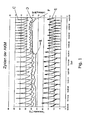
- Fig. 1 shows a representation of the cyclic operation of a Adsorptionshimltemaschine.
- the characteristic discontinuous mode of operation of the machine is characterized by the structure and the changing processes of adsorption and desorption. In order to keep the machine operating as continuously as possible, adsorption and desorption processes are alternately carried out in two adsorbers.
- the fluctuations In the outlet temperature of a heat transfer medium circuit shown in the curve C, the fluctuations are extremely steep and occur cyclically. These fluctuations are also reflected in a damped form at the inlet temperature of the heat transfer circuit at the curve D.
- the cyclical operation of the machine is particularly clearly expressed in the course of a cooling capacity shown by the curve E. In the example shown here, a maximum cooling capacity of 8 kW and a minimum cooling capacity of 2 kW is achieved.
- the outside temperature represented by the curve F shows up to a point X a course with natural fluctuations.
- the sudden increase in the outside temperature at point X is due to incident solar radiation.
- the increase in the outside temperature has a delayed rise in the inlet temperature at curve D and outlet temperature at curve C of the heat transfer circuit result.
- the reduction of the cooling capacity at curve E after point X is due to the temperature increase in the circuit.
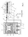
- FIG. 2 shows an exemplary recooling circuit 1 provided for the adsorption refrigerating machine 1
- FIG. 3 an exemplary embodiment of a circuit connected hybrid cooler.
- the recooling circuit contains a suitably arranged outdoors hybrid cooler 2 and a system 3, for example, a Adsorptionskarltemaschine with in Fig. 1 shown operating cycles, which gives off intermittently heat to the recooling circuit.
- the heat carrier flowing in the recooling circuit flows via a feed line 4 from the system into the hybrid cooler. There he transfers the heat absorbed by the system to the ambient air.
- a cooling element 5 is provided in a lamellar construction, which offers a particularly good thermal contact with the environment.
- the cooled in the hybrid cooler heat carrier flows back through a return line 6 to the plant.
- a pump 7 is provided for circulating the heat carrier within the recooling circuit.
- the flow of the heat carrier in the recooling circuit can be regulated via a series of valves. About arranged in the vicinity of the pump check valves 10, the flow can be locked if necessary.
- An associated with the recooling circuit reservoir and expansion tank 11 compensates for pressure fluctuations.
- a process medium flows within a process cycle.
- the process cycle corresponds to the cycle of the adsorbed and desorbed refrigerant which is customary in such systems.
- This exchanges heat via arranged in the circuit heat exchanger, in particular a condenser 13, two adsorbers 14 and an evaporator 15 with adjacent operating components.
- the evaporator 15 is thermally coupled to an external cold water circuit (not shown here).
- an external cold water circuit includes, for example, a cooling ceiling or a cooling coil. These facilities are not shown here.
- the adsorbers 14 are in turn thermally coupled to an external hot water circuit containing, for example, a solar storage, not shown here, a district heating device or a waste heat of a combined heat and power plant.
- an external hot water circuit containing, for example, a solar storage, not shown here, a district heating device or a waste heat of a combined heat and power plant.
- temperature sensors 16 are provided, in particular in the region of the condenser, the evaporator and / or the adsorber. These pass the operating parameters detected at these locations, i. the temperature values measured in this example, to a control unit 17.
- the hybrid cooler already mentioned is a dry hybrid cooler with a spraying device 18 and a ventilation system 19.
- the spraying device consists of a nozzle arrangement 20 arranged below the cooling element 5, which is supplied with cold water from a supply line 21.
- the water supply via the supply line can be released or shut off via a check valve 22.
- the opening state of the check valve is determined by the control unit 17 via a control line 17a and the transmitted via this line electrical switching signals.
- the check valve is for this purpose designed as an electrically switchable valve, for example as a solenoid valve.
- the nozzle arrangement is in the form of a nozzle block under the cooling element.
- the sucked ambient air thus flows first through the nozzle and rips the water sprayed there with it.
- the cooling element is wetted on its surface.
- An evaporation effect which occurs in the air volume flow and on the surface of the finned heat exchanger wall of the cooling element makes it possible to cool the heat carrier to a temperature which is below the ambient temperature.
- the cooling of the heat carrier in the recooling circuit is intensified.
- the spray can be activated or deactivated and thus the effectiveness of the cooling can be adjusted.
- Fig. 4 shows the effect of discontinuous spraying using an exemplary diagram.
- the diagram shows the time course of an exit temperature at the recooler under the influence of a discontinuous heat load during a work cycle of the adsorption chiller. This essentially repeats periodically.
- the curve A shows the temperature profile of the outlet temperature from the recooler without spraying
- the curve B indicates the temperature profile of the outlet temperature with Besprühung.
- the spraying is carried out during the working cycle within two time intervals t S1 . From the course of curve A, it can be seen that the temperature at the outlet of the recooler initially reaches a maximum which asymptotically decreases with time due to the incipient action of the recooler against a limit value.
- the initial temperature maximum is considerably reduced by the spraying during the first time interval t S1 .
- the temperature curve shows a much flatter course.
- the short-term spraying in the two time intervals is thus sufficient to smooth the temperature profile at the outlet of the hybrid cooler and thus a constant cooling capacity of the hybrid cooler to ensure a discontinuous heat load.
- the spraying performed only within the time intervals is sufficient to effectively dissipate the discontinuously supplied heat.
- This effect is caused by the reduced temperature of the ambient air sucked in by the ventilation due to the spraying.
- the temperature profile of the ambient air is represented by the curve B '.
- the beginning and the duration of the respective time intervals t S1 are determined by the control unit.
- the spraying then starts when the temperature T reaches or exceeds a desired value T soll at a point in the refrigeration cycle of the adsorption chiller. It is then turned off and the valve 22 is closed when the predetermined operating parameters, in this case, the target value T set, has fallen again.
- the strong flattening of the curve B in comparison to A is explained by the fact that the spraying of the cooling element in the hybrid cooler already starts before the now more heated heat transfer medium has reached the cooling element via the supply line. As a result, the cooling element is already wetted and can thus absorb the heat introduced by the heat transfer medium very effectively.
- the spraying thus starts at a point in time when the temperature of the heat carrier is still rising.
- the minimum reached in the curve B 'of the air temperature during the time interval t S1 thus coincides with the rising portion of the curve B of the outlet temperature.
- the effectiveness of regulated by the control unit intermittent spraying thus results primarily from the fact that the temperature rise of the heat carrier in the return cooling circuit is met timely and already at the beginning.
- Fig. 5 shows the beneficial influence of in Fig. 4 illustrated embodiment of the spraying on a machine operating a adsorption chiller with such operated recirculating cooling circuit at different ambient temperatures.
- the machine operating rate is a measure of the effectiveness of the adsorption chiller. It indicates the ratio between the heat pumped by the adsorption chiller and the energy required for it. A high machine operating count thus means a high efficiency of the refrigeration system.
- the graph shows that the machine operating count is expected to decrease as the outside temperature increases. It reaches a value of less than 10 without spraying at a temperature of 26 ° C. At this temperature the spraying follows according to the procedure Fig. 3 put into operation, the machine work rate increases significantly to a value of 15 and thus to one and a half times.
Landscapes
- Engineering & Computer Science (AREA)
- Physics & Mathematics (AREA)
- Mechanical Engineering (AREA)
- Thermal Sciences (AREA)
- General Engineering & Computer Science (AREA)
- Sorption Type Refrigeration Machines (AREA)
- Air Conditioning Control Device (AREA)
- Rectifiers (AREA)
Applications Claiming Priority (2)
| Application Number | Priority Date | Filing Date | Title |
|---|---|---|---|
| DE102009051888 | 2009-11-04 | ||
| DE102010008408.5A DE102010008408B4 (de) | 2009-11-04 | 2010-02-18 | Verfahren zum Betreiben eines Rückkühlkreislaufes mit einem Hybridkühler für eine Anlage mit einer diskontinuierlichen Wärmeabgabe und Vorrichtung hierfür |
Publications (3)
| Publication Number | Publication Date |
|---|---|
| EP2320189A2 true EP2320189A2 (fr) | 2011-05-11 |
| EP2320189A3 EP2320189A3 (fr) | 2014-09-03 |
| EP2320189B1 EP2320189B1 (fr) | 2020-07-22 |
Family
ID=43530901
Family Applications (1)
| Application Number | Title | Priority Date | Filing Date |
|---|---|---|---|
| EP10188007.8A Active EP2320189B1 (fr) | 2009-11-04 | 2010-10-19 | Procédé de fonctionnement d'un circuit de refroidissement de recirculation doté d'un refroidisseur hybride pour une installation ayant une sortie de chaleur discontinue |
Country Status (3)
| Country | Link |
|---|---|
| EP (1) | EP2320189B1 (fr) |
| DE (1) | DE102010008408B4 (fr) |
| ES (1) | ES2820876T3 (fr) |
Families Citing this family (2)
| Publication number | Priority date | Publication date | Assignee | Title |
|---|---|---|---|---|
| DE202014101463U1 (de) | 2013-12-23 | 2014-06-20 | Entrade Energiesysteme Ag | Modulare Anlage zur Bereitstellung von thermischer und elektrischer Energie |
| CN109612184A (zh) * | 2018-11-13 | 2019-04-12 | 上海可瑞视冷链科技有限公司 | 一种移动方舱冷凝器的散热装置 |
Family Cites Families (7)
| Publication number | Priority date | Publication date | Assignee | Title |
|---|---|---|---|---|
| HU165521B (fr) | 1972-07-03 | 1974-09-28 | ||
| DE3408192C2 (de) | 1984-03-06 | 1987-03-26 | Markus 8058 Erding Rothmeyer | Verfahren zum Hochtransformieren der Temperatur von Wärme sowie Wärmetransformator |
| DE4215898C2 (de) | 1992-04-09 | 1997-09-04 | E W Gohl Gmbh | Verfahren zum Kühlen von Flüssigkeit in einem geschlossenen Primärkreislauf sowie Kühlvorrichtung dafür |
| DE19906954A1 (de) | 1999-02-19 | 2000-08-24 | E W Gohl Gmbh | Verfahren zum Kühlen von Flüssigkeiten sowie Vorrichtung dafür |
| DE20001528U1 (de) * | 2000-01-28 | 2000-04-06 | Kühlturm GmbH, 76189 Karlsruhe | Kühlvorrichtung |
| US6823684B2 (en) | 2002-02-08 | 2004-11-30 | Tim Allan Nygaard Jensen | System and method for cooling air |
| US7310958B2 (en) | 2004-03-08 | 2007-12-25 | Baltimore Aircoil Company, Inc. | Control of heat exchanger operation |
-
2010
- 2010-02-18 DE DE102010008408.5A patent/DE102010008408B4/de not_active Expired - Fee Related
- 2010-10-19 EP EP10188007.8A patent/EP2320189B1/fr active Active
- 2010-10-19 ES ES10188007T patent/ES2820876T3/es active Active
Non-Patent Citations (1)
| Title |
|---|
| None |
Also Published As
| Publication number | Publication date |
|---|---|
| DE102010008408A1 (de) | 2011-07-14 |
| ES2820876T3 (es) | 2021-04-22 |
| DE102010008408B4 (de) | 2019-07-11 |
| EP2320189A3 (fr) | 2014-09-03 |
| EP2320189B1 (fr) | 2020-07-22 |
Similar Documents
| Publication | Publication Date | Title |
|---|---|---|
| DE2748415C2 (de) | Heizverfahren und bimodales Heizsystem zum Heizen von Gebäuden | |
| DE102011114220B4 (de) | Wärmemanagementsteuerungen für ein Fahrzeug mit einem aufladbaren Energiespeichersystem | |
| DE2754626C2 (de) | Mit einer Energiequelle relativ niedriger Temperatur, insbesondere Solarenergie, arbeitende Kälteanlage | |
| DE3005291A1 (de) | Verfahren und vorrichtung zur konditionierung von luft mittels trocknung durch ein sorbierendes material | |
| DE112013003304T5 (de) | Fahrzeugklimaanlageneinheit | |
| DE3907859C2 (de) | Luftgekühltes Kälteaggregat mit einem Kühlmittelkreislauf | |
| DE102019109003B4 (de) | Laservorrichtung mit wärmeübertragungsvorrichtung zur abgabe von wärme im inneren eines gehäuses nach aussen | |
| EP2199706B1 (fr) | Appareil de climatisation d'un dispositif de commutation et une méthode d'utilisation de l'appareil | |
| DE3938875A1 (de) | Mobiles und transportables klimageraet zur kuehlung und klimatisierung innenliegender raeume | |
| DE102010008408B4 (de) | Verfahren zum Betreiben eines Rückkühlkreislaufes mit einem Hybridkühler für eine Anlage mit einer diskontinuierlichen Wärmeabgabe und Vorrichtung hierfür | |
| EP2187148A1 (fr) | Installation de refroidissement | |
| DE102010016344A1 (de) | Wärmepumpenanlage und Verfahren zur Regelung einer Wärmepumpenanlage | |
| CH649371A5 (en) | Air-conditioning device | |
| EP1792126A1 (fr) | Dispositif pour fournir de la chaleur a au moins un recepteur et evacuer de la chaleur de ce recepteur | |
| DE1288615B (de) | Vorrichtung zur Kuehlung einer Kammer | |
| DE10318655B3 (de) | Klimatisierungssystem für ein Kraftfahrzeug und Verfahren zum Betreiben desselben | |
| EP3480534B1 (fr) | Installation de chauffage et procédé de commande pour une installation de chauffage | |
| EP2837275A2 (fr) | Appareil de refroidissement pour armoire de commande et procédé correspondant | |
| DE102007062343A1 (de) | Verfahren und Anordnung zur Kälteerzeugung nach einem Wasser-Lithiumbromid-Resorptionskälteprozess | |
| DE102008057110A1 (de) | Kühlvorrichtung | |
| AT504762B1 (de) | Wärmepumpe | |
| WO2020182462A9 (fr) | Dispositif de pompe à chaleur, système de chauffage et/ou de préparation d'eau chaude et procédé de fonctionnement d'un dispositif de pompe à chaleur | |
| DE10240659B4 (de) | Verfahren und Vorrichtung zur solarthermischen Kälteerzeugung | |
| EP2216611A1 (fr) | Accumulateur pour fluide frigorigène pour installation de climatisation par absorption mobile | |
| DE69706892T2 (de) | Vorrichtung zur rückkühlung von wärmetauscherkühlmittel |
Legal Events
| Date | Code | Title | Description |
|---|---|---|---|
| PUAI | Public reference made under article 153(3) epc to a published international application that has entered the european phase |
Free format text: ORIGINAL CODE: 0009012 |
|
| AK | Designated contracting states |
Kind code of ref document: A2 Designated state(s): AL AT BE BG CH CY CZ DE DK EE ES FI FR GB GR HR HU IE IS IT LI LT LU LV MC MK MT NL NO PL PT RO RS SE SI SK SM TR |
|
| AX | Request for extension of the european patent |
Extension state: BA ME |
|
| PUAL | Search report despatched |
Free format text: ORIGINAL CODE: 0009013 |
|
| AK | Designated contracting states |
Kind code of ref document: A3 Designated state(s): AL AT BE BG CH CY CZ DE DK EE ES FI FR GB GR HR HU IE IS IT LI LT LU LV MC MK MT NL NO PL PT RO RS SE SI SK SM TR |
|
| AX | Request for extension of the european patent |
Extension state: BA ME |
|
| RIC1 | Information provided on ipc code assigned before grant |
Ipc: F28F 27/00 20060101AFI20140730BHEP Ipc: F25B 17/08 20060101ALI20140730BHEP Ipc: F28D 5/02 20060101ALI20140730BHEP |
|
| 17P | Request for examination filed |
Effective date: 20141209 |
|
| RAP1 | Party data changed (applicant data changed or rights of an application transferred) |
Owner name: FAHRENHEIT GMBH |
|
| STAA | Information on the status of an ep patent application or granted ep patent |
Free format text: STATUS: EXAMINATION IS IN PROGRESS |
|
| 17Q | First examination report despatched |
Effective date: 20190410 |
|
| GRAP | Despatch of communication of intention to grant a patent |
Free format text: ORIGINAL CODE: EPIDOSNIGR1 |
|
| STAA | Information on the status of an ep patent application or granted ep patent |
Free format text: STATUS: GRANT OF PATENT IS INTENDED |
|
| INTG | Intention to grant announced |
Effective date: 20200311 |
|
| GRAS | Grant fee paid |
Free format text: ORIGINAL CODE: EPIDOSNIGR3 |
|
| GRAA | (expected) grant |
Free format text: ORIGINAL CODE: 0009210 |
|
| STAA | Information on the status of an ep patent application or granted ep patent |
Free format text: STATUS: THE PATENT HAS BEEN GRANTED |
|
| AK | Designated contracting states |
Kind code of ref document: B1 Designated state(s): AL AT BE BG CH CY CZ DE DK EE ES FI FR GB GR HR HU IE IS IT LI LT LU LV MC MK MT NL NO PL PT RO RS SE SI SK SM TR |
|
| REG | Reference to a national code |
Ref country code: GB Ref legal event code: FG4D Free format text: NOT ENGLISH |
|
| REG | Reference to a national code |
Ref country code: CH Ref legal event code: EP |
|
| REG | Reference to a national code |
Ref country code: DE Ref legal event code: R096 Ref document number: 502010016706 Country of ref document: DE |
|
| REG | Reference to a national code |
Ref country code: AT Ref legal event code: REF Ref document number: 1293805 Country of ref document: AT Kind code of ref document: T Effective date: 20200815 |
|
| REG | Reference to a national code |
Ref country code: IE Ref legal event code: FG4D Free format text: LANGUAGE OF EP DOCUMENT: GERMAN |
|
| REG | Reference to a national code |
Ref country code: LT Ref legal event code: MG4D |
|
| PG25 | Lapsed in a contracting state [announced via postgrant information from national office to epo] |
Ref country code: NO Free format text: LAPSE BECAUSE OF FAILURE TO SUBMIT A TRANSLATION OF THE DESCRIPTION OR TO PAY THE FEE WITHIN THE PRESCRIBED TIME-LIMIT Effective date: 20201022 Ref country code: SE Free format text: LAPSE BECAUSE OF FAILURE TO SUBMIT A TRANSLATION OF THE DESCRIPTION OR TO PAY THE FEE WITHIN THE PRESCRIBED TIME-LIMIT Effective date: 20200722 Ref country code: BG Free format text: LAPSE BECAUSE OF FAILURE TO SUBMIT A TRANSLATION OF THE DESCRIPTION OR TO PAY THE FEE WITHIN THE PRESCRIBED TIME-LIMIT Effective date: 20201022 Ref country code: GR Free format text: LAPSE BECAUSE OF FAILURE TO SUBMIT A TRANSLATION OF THE DESCRIPTION OR TO PAY THE FEE WITHIN THE PRESCRIBED TIME-LIMIT Effective date: 20201023 Ref country code: FI Free format text: LAPSE BECAUSE OF FAILURE TO SUBMIT A TRANSLATION OF THE DESCRIPTION OR TO PAY THE FEE WITHIN THE PRESCRIBED TIME-LIMIT Effective date: 20200722 Ref country code: HR Free format text: LAPSE BECAUSE OF FAILURE TO SUBMIT A TRANSLATION OF THE DESCRIPTION OR TO PAY THE FEE WITHIN THE PRESCRIBED TIME-LIMIT Effective date: 20200722 Ref country code: PT Free format text: LAPSE BECAUSE OF FAILURE TO SUBMIT A TRANSLATION OF THE DESCRIPTION OR TO PAY THE FEE WITHIN THE PRESCRIBED TIME-LIMIT Effective date: 20201123 Ref country code: LT Free format text: LAPSE BECAUSE OF FAILURE TO SUBMIT A TRANSLATION OF THE DESCRIPTION OR TO PAY THE FEE WITHIN THE PRESCRIBED TIME-LIMIT Effective date: 20200722 |
|
| PG25 | Lapsed in a contracting state [announced via postgrant information from national office to epo] |
Ref country code: LV Free format text: LAPSE BECAUSE OF FAILURE TO SUBMIT A TRANSLATION OF THE DESCRIPTION OR TO PAY THE FEE WITHIN THE PRESCRIBED TIME-LIMIT Effective date: 20200722 Ref country code: PL Free format text: LAPSE BECAUSE OF FAILURE TO SUBMIT A TRANSLATION OF THE DESCRIPTION OR TO PAY THE FEE WITHIN THE PRESCRIBED TIME-LIMIT Effective date: 20200722 Ref country code: RS Free format text: LAPSE BECAUSE OF FAILURE TO SUBMIT A TRANSLATION OF THE DESCRIPTION OR TO PAY THE FEE WITHIN THE PRESCRIBED TIME-LIMIT Effective date: 20200722 Ref country code: IS Free format text: LAPSE BECAUSE OF FAILURE TO SUBMIT A TRANSLATION OF THE DESCRIPTION OR TO PAY THE FEE WITHIN THE PRESCRIBED TIME-LIMIT Effective date: 20201122 |
|
| PG25 | Lapsed in a contracting state [announced via postgrant information from national office to epo] |
Ref country code: NL Free format text: LAPSE BECAUSE OF FAILURE TO SUBMIT A TRANSLATION OF THE DESCRIPTION OR TO PAY THE FEE WITHIN THE PRESCRIBED TIME-LIMIT Effective date: 20200722 |
|
| REG | Reference to a national code |
Ref country code: ES Ref legal event code: FG2A Ref document number: 2820876 Country of ref document: ES Kind code of ref document: T3 Effective date: 20210422 |
|
| REG | Reference to a national code |
Ref country code: DE Ref legal event code: R097 Ref document number: 502010016706 Country of ref document: DE |
|
| PG25 | Lapsed in a contracting state [announced via postgrant information from national office to epo] |
Ref country code: SM Free format text: LAPSE BECAUSE OF FAILURE TO SUBMIT A TRANSLATION OF THE DESCRIPTION OR TO PAY THE FEE WITHIN THE PRESCRIBED TIME-LIMIT Effective date: 20200722 Ref country code: RO Free format text: LAPSE BECAUSE OF FAILURE TO SUBMIT A TRANSLATION OF THE DESCRIPTION OR TO PAY THE FEE WITHIN THE PRESCRIBED TIME-LIMIT Effective date: 20200722 Ref country code: CZ Free format text: LAPSE BECAUSE OF FAILURE TO SUBMIT A TRANSLATION OF THE DESCRIPTION OR TO PAY THE FEE WITHIN THE PRESCRIBED TIME-LIMIT Effective date: 20200722 Ref country code: DK Free format text: LAPSE BECAUSE OF FAILURE TO SUBMIT A TRANSLATION OF THE DESCRIPTION OR TO PAY THE FEE WITHIN THE PRESCRIBED TIME-LIMIT Effective date: 20200722 Ref country code: EE Free format text: LAPSE BECAUSE OF FAILURE TO SUBMIT A TRANSLATION OF THE DESCRIPTION OR TO PAY THE FEE WITHIN THE PRESCRIBED TIME-LIMIT Effective date: 20200722 |
|
| PLBE | No opposition filed within time limit |
Free format text: ORIGINAL CODE: 0009261 |
|
| STAA | Information on the status of an ep patent application or granted ep patent |
Free format text: STATUS: NO OPPOSITION FILED WITHIN TIME LIMIT |
|
| PG25 | Lapsed in a contracting state [announced via postgrant information from national office to epo] |
Ref country code: AL Free format text: LAPSE BECAUSE OF FAILURE TO SUBMIT A TRANSLATION OF THE DESCRIPTION OR TO PAY THE FEE WITHIN THE PRESCRIBED TIME-LIMIT Effective date: 20200722 |
|
| REG | Reference to a national code |
Ref country code: CH Ref legal event code: PL |
|
| 26N | No opposition filed |
Effective date: 20210423 |
|
| PG25 | Lapsed in a contracting state [announced via postgrant information from national office to epo] |
Ref country code: SK Free format text: LAPSE BECAUSE OF FAILURE TO SUBMIT A TRANSLATION OF THE DESCRIPTION OR TO PAY THE FEE WITHIN THE PRESCRIBED TIME-LIMIT Effective date: 20200722 Ref country code: LU Free format text: LAPSE BECAUSE OF NON-PAYMENT OF DUE FEES Effective date: 20201019 Ref country code: MC Free format text: LAPSE BECAUSE OF FAILURE TO SUBMIT A TRANSLATION OF THE DESCRIPTION OR TO PAY THE FEE WITHIN THE PRESCRIBED TIME-LIMIT Effective date: 20200722 |
|
| REG | Reference to a national code |
Ref country code: BE Ref legal event code: MM Effective date: 20201031 |
|
| PG25 | Lapsed in a contracting state [announced via postgrant information from national office to epo] |
Ref country code: BE Free format text: LAPSE BECAUSE OF NON-PAYMENT OF DUE FEES Effective date: 20201031 Ref country code: CH Free format text: LAPSE BECAUSE OF NON-PAYMENT OF DUE FEES Effective date: 20201031 Ref country code: SI Free format text: LAPSE BECAUSE OF FAILURE TO SUBMIT A TRANSLATION OF THE DESCRIPTION OR TO PAY THE FEE WITHIN THE PRESCRIBED TIME-LIMIT Effective date: 20200722 Ref country code: LI Free format text: LAPSE BECAUSE OF NON-PAYMENT OF DUE FEES Effective date: 20201031 |
|
| REG | Reference to a national code |
Ref country code: NL Ref legal event code: MP Effective date: 20200722 |
|
| PG25 | Lapsed in a contracting state [announced via postgrant information from national office to epo] |
Ref country code: IE Free format text: LAPSE BECAUSE OF NON-PAYMENT OF DUE FEES Effective date: 20201019 |
|
| REG | Reference to a national code |
Ref country code: AT Ref legal event code: MM01 Ref document number: 1293805 Country of ref document: AT Kind code of ref document: T Effective date: 20201019 |
|
| REG | Reference to a national code |
Ref country code: ES Ref legal event code: FD2A Effective date: 20220127 |
|
| PG25 | Lapsed in a contracting state [announced via postgrant information from national office to epo] |
Ref country code: AT Free format text: LAPSE BECAUSE OF NON-PAYMENT OF DUE FEES Effective date: 20201019 |
|
| PGFP | Annual fee paid to national office [announced via postgrant information from national office to epo] |
Ref country code: DE Payment date: 20211020 Year of fee payment: 12 Ref country code: GB Payment date: 20211022 Year of fee payment: 12 |
|
| PGFP | Annual fee paid to national office [announced via postgrant information from national office to epo] |
Ref country code: IT Payment date: 20211029 Year of fee payment: 12 Ref country code: FR Payment date: 20211021 Year of fee payment: 12 |
|
| PG25 | Lapsed in a contracting state [announced via postgrant information from national office to epo] |
Ref country code: TR Free format text: LAPSE BECAUSE OF FAILURE TO SUBMIT A TRANSLATION OF THE DESCRIPTION OR TO PAY THE FEE WITHIN THE PRESCRIBED TIME-LIMIT Effective date: 20200722 Ref country code: MT Free format text: LAPSE BECAUSE OF FAILURE TO SUBMIT A TRANSLATION OF THE DESCRIPTION OR TO PAY THE FEE WITHIN THE PRESCRIBED TIME-LIMIT Effective date: 20200722 Ref country code: ES Free format text: LAPSE BECAUSE OF NON-PAYMENT OF DUE FEES Effective date: 20201020 Ref country code: CY Free format text: LAPSE BECAUSE OF FAILURE TO SUBMIT A TRANSLATION OF THE DESCRIPTION OR TO PAY THE FEE WITHIN THE PRESCRIBED TIME-LIMIT Effective date: 20200722 |
|
| PG25 | Lapsed in a contracting state [announced via postgrant information from national office to epo] |
Ref country code: MK Free format text: LAPSE BECAUSE OF FAILURE TO SUBMIT A TRANSLATION OF THE DESCRIPTION OR TO PAY THE FEE WITHIN THE PRESCRIBED TIME-LIMIT Effective date: 20200722 |
|
| REG | Reference to a national code |
Ref country code: DE Ref legal event code: R119 Ref document number: 502010016706 Country of ref document: DE |
|
| GBPC | Gb: european patent ceased through non-payment of renewal fee |
Effective date: 20221019 |
|
| PG25 | Lapsed in a contracting state [announced via postgrant information from national office to epo] |
Ref country code: FR Free format text: LAPSE BECAUSE OF NON-PAYMENT OF DUE FEES Effective date: 20221031 Ref country code: DE Free format text: LAPSE BECAUSE OF NON-PAYMENT OF DUE FEES Effective date: 20230503 |
|
| PG25 | Lapsed in a contracting state [announced via postgrant information from national office to epo] |
Ref country code: IT Free format text: LAPSE BECAUSE OF NON-PAYMENT OF DUE FEES Effective date: 20221019 Ref country code: GB Free format text: LAPSE BECAUSE OF NON-PAYMENT OF DUE FEES Effective date: 20221019 |