EP2320430A2 - Protonenstrahltherapiesteuersystem - Google Patents
Protonenstrahltherapiesteuersystem Download PDFInfo
- Publication number
- EP2320430A2 EP2320430A2 EP10178575A EP10178575A EP2320430A2 EP 2320430 A2 EP2320430 A2 EP 2320430A2 EP 10178575 A EP10178575 A EP 10178575A EP 10178575 A EP10178575 A EP 10178575A EP 2320430 A2 EP2320430 A2 EP 2320430A2
- Authority
- EP
- European Patent Office
- Prior art keywords
- hardware
- client
- agent
- instructions
- monitor
- Prior art date
- Legal status (The legal status is an assumption and is not a legal conclusion. Google has not performed a legal analysis and makes no representation as to the accuracy of the status listed.)
- Withdrawn
Links
Images


Classifications
-
- A—HUMAN NECESSITIES
- A61—MEDICAL OR VETERINARY SCIENCE; HYGIENE
- A61N—ELECTROTHERAPY; MAGNETOTHERAPY; RADIATION THERAPY; ULTRASOUND THERAPY
- A61N5/00—Radiation therapy
- A61N5/10—X-ray therapy; Gamma-ray therapy; Particle-irradiation therapy
- A61N5/1077—Beam delivery systems
- A61N5/1079—Sharing a beam by multiple treatment stations
-
- A—HUMAN NECESSITIES
- A61—MEDICAL OR VETERINARY SCIENCE; HYGIENE
- A61N—ELECTROTHERAPY; MAGNETOTHERAPY; RADIATION THERAPY; ULTRASOUND THERAPY
- A61N5/00—Radiation therapy
- A61N5/10—X-ray therapy; Gamma-ray therapy; Particle-irradiation therapy
-
- G—PHYSICS
- G16—INFORMATION AND COMMUNICATION TECHNOLOGY [ICT] SPECIALLY ADAPTED FOR SPECIFIC APPLICATION FIELDS
- G16H—HEALTHCARE INFORMATICS, i.e. INFORMATION AND COMMUNICATION TECHNOLOGY [ICT] SPECIALLY ADAPTED FOR THE HANDLING OR PROCESSING OF MEDICAL OR HEALTHCARE DATA
- G16H40/00—ICT specially adapted for the management or administration of healthcare resources or facilities; ICT specially adapted for the management or operation of medical equipment or devices
- G16H40/60—ICT specially adapted for the management or administration of healthcare resources or facilities; ICT specially adapted for the management or operation of medical equipment or devices for the operation of medical equipment or devices
- G16H40/63—ICT specially adapted for the management or administration of healthcare resources or facilities; ICT specially adapted for the management or operation of medical equipment or devices for the operation of medical equipment or devices for local operation
-
- G—PHYSICS
- G16—INFORMATION AND COMMUNICATION TECHNOLOGY [ICT] SPECIALLY ADAPTED FOR SPECIFIC APPLICATION FIELDS
- G16Z—INFORMATION AND COMMUNICATION TECHNOLOGY [ICT] SPECIALLY ADAPTED FOR SPECIFIC APPLICATION FIELDS, NOT OTHERWISE PROVIDED FOR
- G16Z99/00—Subject matter not provided for in other main groups of this subclass
-
- H—ELECTRICITY
- H04—ELECTRIC COMMUNICATION TECHNIQUE
- H04L—TRANSMISSION OF DIGITAL INFORMATION, e.g. TELEGRAPHIC COMMUNICATION
- H04L67/00—Network arrangements or protocols for supporting network services or applications
- H04L67/01—Protocols
- H04L67/12—Protocols specially adapted for proprietary or special-purpose networking environments, e.g. medical networks, sensor networks, networks in vehicles or remote metering networks
-
- H—ELECTRICITY
- H04—ELECTRIC COMMUNICATION TECHNIQUE
- H04L—TRANSMISSION OF DIGITAL INFORMATION, e.g. TELEGRAPHIC COMMUNICATION
- H04L67/00—Network arrangements or protocols for supporting network services or applications
- H04L67/50—Network services
- H04L67/60—Scheduling or organising the servicing of application requests, e.g. requests for application data transmissions using the analysis and optimisation of the required network resources
-
- H—ELECTRICITY
- H04—ELECTRIC COMMUNICATION TECHNIQUE
- H04L—TRANSMISSION OF DIGITAL INFORMATION, e.g. TELEGRAPHIC COMMUNICATION
- H04L69/00—Network arrangements, protocols or services independent of the application payload and not provided for in the other groups of this subclass
- H04L69/30—Definitions, standards or architectural aspects of layered protocol stacks
- H04L69/32—Architecture of open systems interconnection [OSI] 7-layer type protocol stacks, e.g. the interfaces between the data link level and the physical level
- H04L69/322—Intralayer communication protocols among peer entities or protocol data unit [PDU] definitions
- H04L69/329—Intralayer communication protocols among peer entities or protocol data unit [PDU] definitions in the application layer [OSI layer 7]
-
- A—HUMAN NECESSITIES
- A61—MEDICAL OR VETERINARY SCIENCE; HYGIENE
- A61N—ELECTROTHERAPY; MAGNETOTHERAPY; RADIATION THERAPY; ULTRASOUND THERAPY
- A61N5/00—Radiation therapy
- A61N5/10—X-ray therapy; Gamma-ray therapy; Particle-irradiation therapy
- A61N5/1048—Monitoring, verifying, controlling systems and methods
- A61N2005/1074—Details of the control system, e.g. user interfaces
-
- A—HUMAN NECESSITIES
- A61—MEDICAL OR VETERINARY SCIENCE; HYGIENE
- A61N—ELECTROTHERAPY; MAGNETOTHERAPY; RADIATION THERAPY; ULTRASOUND THERAPY
- A61N5/00—Radiation therapy
- A61N5/10—X-ray therapy; Gamma-ray therapy; Particle-irradiation therapy
- A61N2005/1085—X-ray therapy; Gamma-ray therapy; Particle-irradiation therapy characterised by the type of particles applied to the patient
- A61N2005/1087—Ions; Protons
Definitions
- the present invention relates to distributed control systems and, in particular, concerns a control system for managing data communications in a distributed environment for a proton beam therapy device.
- proton beam therapy wherein protons form the energy stream used to irradiate the target regions of the patient.
- proton beam therapy requires the patient to be accurately positioned with respect to the beam source so that the proton stream irradiates only the desired target region. Otherwise, the stream could damage other healthy cells within the patient's body.
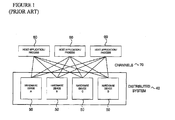
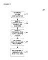
- Figure 1 illustrates a conventional distributed system 40 comprising a plurality of hardware devices 50 each of which perform selected operations and tasks. Control and maintenance of the hardware devices 50 is coordinated using one or more host applications or processes 60 which communicate with the hardware devices 50 through a plurality of communication channels or data paths 70. For each hardware device 50 that the host application or process 60 communicates, a separate communications channel 70 is typically established.
- This system architecture should be able to accommodate the complexity and bandwidth demands of the proton beam therapy system while maintaining an acceptable level of simplicity so as to facilitate scaling, maintenance, and development. Additionally, the system should provide improved system monitoring features that resolve potential problems associated with monitoring off-line or malfunctioning devices.
- the communications system architecture reduces channel or socket utilization by multiple processes using a routing/multiplexing functionality of the agent to resolve potential bottlenecks encountered coordinating data exchange between the hardware devices.
- the communications system further provides a constant monitoring capability for embedded systems using a proctor module.
- the architecture further comprises a monitor component associated with each hardware device used to receive instructions from the host application routed through the agent and transform the instructions into a hardware recognized form that are subsequently executed on the hardware device, the monitor component further used to receive an information response from the hardware device and forward the information response back to the host application through agent.
- the architecture also incorporates a proctor component resident in the monitor component which evaluates the information response obtained from the hardware device and identifies anomalous hardware behavior and further issues one or more safety measures when anomalous hardware behavior is detected.
- This method further comprises the steps of: (1) establishing a first communication channel between each host application and an agent device which is configured to communicate with the host application and receive the transmitted instructions, (2) establishing a plurality of second communication channels between the agent device and each hardware device such that each hardware device is connected to the agent by a single communication channel, (3) routing the instructions issued by the host applications using the agent device such that the instructions are forwarded to the appropriate hardware device in a substantially transparent manner, and (4) receiving the instructions using a monitor module residing on each hardware device which transforms the instructions into a hardware recognized format to be subsequently executed by the hardware device.
- the invention comprises a method for communicating and controlling a distributed system of network resources wherein a first communication channel is established between a client device and an agent device, a second communication channel is established between the agent device and at least one hardware device, and data transferred between the client device and the agent device and furthermore the agent device and the monitor device is processed according to a client process which requests access to the distributed system of hardware resources, an agent process which manages the communication channels and provides routing for client process requests, and a monitor process which accepts requests from the agent process, executes the requests, and returns any results to the client process.
- FIG. 2 illustrates one embodiment of a proton beam therapy system (PBTS) 100 for patient treatment that is coupled to one or more host applications 105.
- the host applications 105 communicate with a plurality of functional components 110 used in conjunction with a treatment station 115.
- the functional components 110 comprise monitoring and management components that direct the activities of the treatment station 115.
- Each functional component 110 further comprises one or more hardware devices present in the treatment station 115 which are desirably associated and collectively managed within the particle beam therapy system 100.
- the operation of these hardware devices are desirably coordinated to direct a precisely calibrated and aligned proton beam 147 towards a specific target region or isocenter 148 of the patient 120.
- the treatment station 115 comprises a proton source 125 connected to an accelerator 130 by an injector 135.
- the accelerator 130 accelerates protons to a desired energy level and, via a beam transport apparatus 140, delivers the proton beam to the patient 120 who is supported in a fixed position at a treatment station 115.
- the beam transport apparatus 140 further comprises a nozzle 150 which directs the particle stream towards a specific target isocenter within the body of the patient 120.
- the patient 120 is supported by a gantry 145 which is rotatable about an axis of rotation and is used to properly align the proton beam. Additional details of the proton beam therapy system 100 can be found in commonly assigned U.S. Pat. No. 5,866,912 and U.S. Pat. No. 4,870,287 which are hereby incorporated by reference.
- the functional components 110 monitor and coordinate the activities of the hardware subsystems used to configure and direct the proton beam as well as insure patient safety.
- Patient safety is a primary concern in radiation treatment and strict control over the proton beam therapy system must be maintained at all times to insure that the beam is always directed with an appropriate intensity or energy level.
- the beam therapy system is configured in such a manner so as to prevent the beam from contacting the patient unless the hardware devices and subsystems can be confirmed to be in a ready condition and appropriately configured.
- the ready condition indicates that the hardware devices and subsystems are performing within tolerances and at the specific range determined to be suitable for patient treatment.
- the proton beam is disabled until all subsystems can be confirmed to be in this ready condition.
- the configuration of the functional components 110 and tiered communications system provides necessary coordination functionality to monitor the state of readiness of the proton beam therapy device to determine when it is appropriate to administer patient treatment.
- the connectivity between the host applications 105 and the agent device 215 as well as the agent device 215 and the hardware devices 210 comprises a networking connection which uses a suitable protocol such as Berkley sockets based Transmission Control Protocol, Internet Protocol (TCP/IP) or User Datagram Protocol, Internet Protocol (UDP/IP).
- TCP/IP Internet Protocol
- UDP/IP User Datagram Protocol
- the widespread interoperability of the sockets-hased protocol may be advantageously used in the tiered communications system to provide a commonly-recognized communications protocol which each hardware device 210 is capable of using to transmit and receive information.
- tiered communications architecture 200 is not necessarily limited for use with the aforementioned sockets-based protocol but rather may be adapted for use with numerous other communications protocols including for example remote message passing protocols.
- the implementation of other protocols with the tiered communications architecture 200 is therefore understood to be representative of other embodiments of the present invention.
- tiered communication architecture 200 may advantageously be configured for use with existing distributed systems permitting these systems to be retrofitted with this new communications architecture and benefit from reduced channels number and complexity.
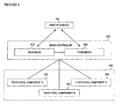
- the clients 320 comprise control components 335 and user interfaces 330.
- the control components 335 interact with the functional component 302 and exchange information with the underlying hardware devices 210 to carry out designated control functions.
- Each control component 335 may further connect to one or more user interfaces 330 to receive input from users and direct information back to the user interface 330 as needed.
- one or more control components 335 may interface with other control components 335 to provide a means for direct communication between desired control components 335.
- the control components 335 provide a means for collaboration between a plurality of functional components 302. This collaboration is directed by a one or more specialized controller components referred to as a brain controller 222.
- brain controllers 222 may desirably utilize the services of the functional components 302 directly or indirectly by connecting to other brain controllers 222. Additional details of the brain controller configuration and function will be described in greater detail in connection with Figure 8 .
- the user interface 330 can directly interface with the functional component 302 and bypass communication channels through the control components 335 and brain controllers 222.
- This mode of communication may be used for example, in logging operations, fetching configuration parameters, and data stream applications to transmit information directly between hardware devices 210 of the functional component 302 and the user interface 330.
- the aforementioned agent 215 resides in the general purpose tier 315 of the functional component 302.
- Each functional component 302 may be associated with an agent 215 that serves as a routing device for messages and information between the client 320 and the underlying hardware devices 210.
- the information transmitted by the client comprises commands, instructions, requests or the like which are desirably issued by the client 320 to monitor and control the hardware devices 210.
- the agent 215 receives this information from the client 320 and forwards it to one or more monitors 340 which service the communication needs for the underlying hardware devices 210 of the functional component 302. Additionally the agent 215 may be configured to broadcast the desired information to all monitors 340 in the functional component 302 simultaneously depending upon the nature of the information.
- the client proxy maintains a lookup table that maps the addresses of the clients 320 to their network address (i.e. soft IP address). This table is built as messages are received and the entries added to the table are used for routing replies to the messages back to the client 320. Additionally, the agent 215 may maintain configuration data comprising monitor mapping information which is used by the monitor proxy 226 for routing messages to the corresponding destination monitors 340. This information may also be used by the agent 215 to determine which monitors 340 and associated hardware devices 210 are in a particular functional area 302. As a result, a single agent 215 may be configured to coordinate network communications for a plurality of functional components 302 and corresponding hardware devices 210.
- the agent may further implement various security operations which prevent unauthorized access to the distributed system or selectively block clients 320 which are not recognized for purposes of information transmission at a particular time.
- One method by which the agent 215 may perform these security operations is to restrict open client channels 200 to only those for clients 320 currently recognized or allowed. It will be appreciated that these security measures may be desirably implemented in the proton beam therapy system to improve patient safety and system security.
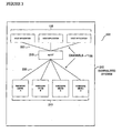
- the monitors 340 reside at the embedded tier 315 for each functional component 302 and are responsible for exchanging data and information with the agent 215 of the general purpose tier 315. As will be described in greater detail herein below the monitor 340 comprises a plurality of cooperative modules that are responsible for performing functions including information reception, command interpretation and translation, data acquisition, data presentation, and information transmission.
- Figure 5 illustrates the cooperative modules of the monitor 340 which reside between the agent 215 and the hardware device 210.
- the functional components of the monitor 240 include including a proxy 351, a command processor 352, a proctor 353, a hardware abstraction layer 354, and a driver 355.
- the activities of these components are desirably coordinated to carry out tasks associated with the processing of information received from clients 320 through the agent 215 and presenting this information to the underlying hardware device 210 in a recognizable form.
- each hardware device 210 recognizes a limited and highly dedicated command set which may include specialized bit/memory addressing or register-level commands. These command language definitions and addressing schemes are not typically shared between hardware devices 210 of different classes (e.g. temperature monitors and dosimetry monitors). Additionally, similar hardware devices 210 from different manufacturers may utilize different command structures. Furthermore, the data output and format will typically vary from one hardware device 210 to the next and the data output may be in a format or unit designation which is to be desirably altered for presentation to the client 320 or other functional components 302. Therefore, in order to communicate with each hardware device 210 a specialized interpreter must be employed.
- the driver 351 provides a wrapper Application Programming Interface (API) to be used to access the underlying hardware device 210. Additionally the driver 351 can be implemented as a collection of thread safe functions which execute as requested by upper-level modules of the monitor 340. The driver 351 typically interfaces with the associated hardware device 210 using memory mapped access to the hardware's registers. Driver interfacing in this manner may utilize a processor contained in the hardware device 210 or a peripheral control card used to control the hardware device 210. This configuration may be referred to as an embedded crate where the crate comprises the hardware device 210, the driver 351, a processor upon which the driver 351 executes and a controller card used by the driver 351 to control the hardware device 210.
- API Application Programming Interface
- the hardware abstraction layer (HAL) 354 provides necessary hardware abstraction using the drivers 351 and forms a bridge between the presentation of information by the clients 320 and that of the hardware device 210.
- the HAL 354 further serves as a translator between the services provided by the distributed system and the hardware device 210 that performs the job. This feature of the HAL 354 significantly reduces problems and difficulties associated with trying to keep each part of the distributed system aware of the current implementation and command structure of each hardware device 210 contained in the functional component 302.
- the HAL 354 may also provide mechanisms for consolidating a drivers 355 and associated hardware devices 210 into a single meta-device.
- the meta-device appears logically to the clients 320 as single unit of hardware.
- Hardware consolidation in this manner desirably reduces the apparent complexity of the system and facilitates monitoring and command of the hardware components of the distributed system.
- a beam scatterer meta-device may be defined as comprising hardware devices 210 including one or more resolvers, a motor controller, digital input, and serial port communications.
- HAL 354 may be used to internally maintain the mapping of each hardware device 210 within the functional component 302 such that the clients 320 are not required to have knowledge of the specific address or path to the device 210. Instead, the clients 320 may simply direct a command to the monitor 340 which may be subsequently processed and routed to the appropriate hardware device(s) as determined by the HAL 354. It will be appreciated that this feature significantly reduces the mapping complexity in complex distributed systems and provides for improved device transparency. Device transparency is a desirably characteristic as it reduces the apparent complexity of the distributed system and is an aid to developers who are freed from having to discern the actual layout or topology of the hardware devices 210. Additionally, the HAL 354 may be readily redefined to permit modification of the underlying hardware devices 210 or alterations in the composition of devices in the functional component 302 without necessitating substantial reworking of the clients 320.
- the monitor 340 further comprises one or more proctors 353 which monitor the performance of the associated hardware devices 210 and acts as handlers for anomalous or undesirable device behavior within the functional components 302.
- the proctor 353 evaluates the requirements and/or needs of the hardware devices 210 of the functional component 302. Functions performed by the proctor 353 may include monitoring for correct system settings and identifying out of range parameters.
- the proctor 353 identifies anomalous device behavior by interpreting data and information received from the hardware device 210.
- the proctor 353 maintains knowledge of desired tolerances and ranges for hardware devices 210 within the functional component 302 and determines if the hardware devices 210 are performing within desired parameters by comparing actual hardware information with the designated tolerances and ranges.
- anomalous device behavior in the proton beam therapy system may be identified by evaluating one or more critical variables 357 such as ring energy, power supply output, magnetic field strength, and/or delivered dose. When the value of a critical variable 357 is observed to be outside of the maximum limits or tolerances, the proctor 353 may recognize and report this event.
- the anomalous behavior may be identified when the critical variable deviates by more than a given limit from a normal value (e.g. a power spike). Additionally, the anomalous behavior may be observed as an adverse trend where the moving average of the deviation is projected by the proctor 353 to be likely out tolerance in a certain time interval.
- a normal value e.g. a power spike
- a power supply for the proton beam therapy device 100 may be monitored by the proctor 353 to insure that the output power is consistent with the requested or desired power. Furthermore, the proctor 353 may insure that there are no internal faults within the power supply system. If the proctor 353 for the power supply detects a fault or observes the power supply is not operating within normal parameters, the proctor may generate a report which is transmitted to an outside system thereby giving advance warning of the failure even without a control application or client running. Furthermore, the proctor 353 may take corrective action to restore the power supply to normal operation by instructing the monitor to issue hardware-recognized commands which perform a corrective or restorative function.
- the command processor 352 logically resides directly above the proctor 353 and the HAL 354 both of which are independently connected to this component.
- the function of the command processor 352 is to interpret and execute incoming instructions received from clients 320. Additionally, the command process provides reply messages in the form of requested data and information received from the hardware device 210.
- the communications proxy 351 logically resides above the command processor 352 and receives incoming data and information from one of more channels associated with the agent 215 and forwards this information directly to the command processor 352.
- the communications proxy 351 typically does not posses any specialized command or instruction interpreters unlike other components of the monitor 340 but rather is used for information reception and dissemination. Additionally the communication proxy 351 accepts outgoing messages comprising requested information from the command processor 352 and forwards the outgoing message to the appropriate client(s) 320 through the agent 215.
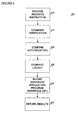
- Figure 6 illustrates a process for command or instruction execution using the aforementioned monitor 340.
- the process commences in a state 410 where an instruction is received from a client 320 that has been forwarded through the agent 215.
- Command reception is handled by the communications proxy 351 which maintains an open channel with the agent 215.
- the communications proxy 351 additionally verifies the source of the incoming instruction by identifying the address, channel or IP number from which the instruction originated. This information is used by the communications proxy 351 to identify which client(s) the instruction results should be sent when they are ready.
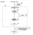
- Figure 7 illustrates an information exchange process using the agent 215 to communicate with the client devices 320 and the monitor 340.
- the process commences in a state 510 where upon startup of the distributed system, the agent 215 identifies the configuration of the system and the location of the monitor(s) 430 in use for each of the required functional components 302.
- the configuration of the system is determined by accessing a central configuration file or system which contains channel mapping characteristics to associated crates or hardware devices 210.
- the agent 215 identifies a listening port that defines a dedicated port or channel 155 that will be bound for providing client access. Once this information has been obtained from the central configuration file or system, the agent 215 is bound to the listening port in state 515 and proceeds to establish a connection to each monitor 340 that the agent 215 has been designated to have access.
- the agent 215 When the agent 215 receives a reply containing the results of the instruction from the monitor 340 in state 530, the agent 215 forwards the reply to the appropriate client(s) 320 as determined by the listening port and central configuration file. Thus the agent 215 acts as a intermediary between each client 320 and the hardware associated monitors 340.
- Figure 8 illustrates one embodiment of a brain controller 222 that is used to coordinate command and monitoring activities in the distributed system.
- the brain controller 222 provides additional computational functionality which is useful in aggregating a plurality of functional components 302 together to form a logical meta-device 630.
- the mate-device 630 represents a complex functional domain that requires collaboration between the plurality of functional components 302 in order to provide a desired service type.
- the brain controller 222 may be further subdivided into a hind-brain 610 and fore-brain 620.
- the hind brain 610 typically performs operations that do not require extensive decision making or analytical comparisons.
- the hind brain 610 may be used to connect to a plurality of systems or functional components 302 and perform operations such as monitoring and/or operation functions.
- the hind brain 610 functions autonomously without direct user input from the user interface 330 and interacts directly with one or more functional components 302 through the networking,connections or channels 155.
- the hind brain 610 may be configured to display the status or results of its activities to the user through the user interface 330 however this function is not necessarily required for hind-brain operation.
- the hind brain 610 may additionally function as an agent for the meta-device 630 which is in turn networked to other agents 215 to provide a means for associating many systems or functional components 302 together.
- the proton beam therapy system may implement a beam obstruction meta-device which desirably monitors a plurality of separate functional components 302 spread throughout the distributed system, each with their own agent 215.
- the beam obstruction meta-device may further require knowledge of the treatment mode the particle beam therapy device is currently in.
- the beam obstruction meta-device may require knowledge of the treatment station 115 which is to receive the proton beam. Using the information obtained from each of these sources the hind brain 610 decides when it is safe to allow the proton beam to be engaged. Because this process involves the coordination of a plurality of functional components 302 spread across the distributed system, a single HAL 354 is typically not suitable to perform operations of this complexity and thus the meta-device may be desirably used to accomplish similar functions.
- the fore-brain 620 provides increased analytical functionality compared to the hind-brain 610 and is responsible for implementing complex active control operations.
- the fore-brain 620 creates operational state machines that ensure the correct steps are taken to perform a particular operation.
- the fore-brain 620 may be responsible for controlling and monitoring the steps necessary to administer a patient treatment.
- the fore-brain accomplishes this task by communicating with a plurality of agents 215 and hind-brains 610 sending commands and receiving responses which are used to coordinate the activities of the underlying hardware devices 210.
- the fore-brain 620 therefore directs the activities of the various subsystems to perform distributed system tasks in a coordinated manner.
- each fore-brain 620 is typically connected to a user interface 330 which is used to interact with the fore-brain 620 directing various system actions and receiving responses or status updates as needed or required.
Landscapes
- Engineering & Computer Science (AREA)
- Health & Medical Sciences (AREA)
- Biomedical Technology (AREA)
- General Health & Medical Sciences (AREA)
- Computer Networks & Wireless Communication (AREA)
- Signal Processing (AREA)
- Public Health (AREA)
- Pathology (AREA)
- Medical Informatics (AREA)
- Animal Behavior & Ethology (AREA)
- Radiology & Medical Imaging (AREA)
- Nuclear Medicine, Radiotherapy & Molecular Imaging (AREA)
- Veterinary Medicine (AREA)
- Life Sciences & Earth Sciences (AREA)
- Computing Systems (AREA)
- Business, Economics & Management (AREA)
- General Business, Economics & Management (AREA)
- Epidemiology (AREA)
- Primary Health Care (AREA)
- Computer Security & Cryptography (AREA)
- Radiation-Therapy Devices (AREA)
Applications Claiming Priority (2)
| Application Number | Priority Date | Filing Date | Title |
|---|---|---|---|
| US25446700P | 2000-12-08 | 2000-12-08 | |
| EP01990961A EP1352399A4 (de) | 2000-12-08 | 2001-12-10 | Protonenstrahltherapiesteuersystem |
Related Parent Applications (2)
| Application Number | Title | Priority Date | Filing Date |
|---|---|---|---|
| EP01990961A Division EP1352399A4 (de) | 2000-12-08 | 2001-12-10 | Protonenstrahltherapiesteuersystem |
| EP01990961.3 Division | 2001-12-10 |
Publications (2)
| Publication Number | Publication Date |
|---|---|
| EP2320430A2 true EP2320430A2 (de) | 2011-05-11 |
| EP2320430A3 EP2320430A3 (de) | 2012-09-05 |
Family
ID=22964419
Family Applications (3)
| Application Number | Title | Priority Date | Filing Date |
|---|---|---|---|
| EP10178573A Withdrawn EP2320431A3 (de) | 2000-12-08 | 2001-12-10 | Protonenstrahltherapiesteuersystem |
| EP01990961A Withdrawn EP1352399A4 (de) | 2000-12-08 | 2001-12-10 | Protonenstrahltherapiesteuersystem |
| EP10178575A Withdrawn EP2320430A3 (de) | 2000-12-08 | 2001-12-10 | Protonenstrahltherapiesteuersystem |
Family Applications Before (2)
| Application Number | Title | Priority Date | Filing Date |
|---|---|---|---|
| EP10178573A Withdrawn EP2320431A3 (de) | 2000-12-08 | 2001-12-10 | Protonenstrahltherapiesteuersystem |
| EP01990961A Withdrawn EP1352399A4 (de) | 2000-12-08 | 2001-12-10 | Protonenstrahltherapiesteuersystem |
Country Status (5)
| Country | Link |
|---|---|
| US (3) | US7398309B2 (de) |
| EP (3) | EP2320431A3 (de) |
| JP (1) | JP4467237B2 (de) |
| AU (2) | AU2002230718B2 (de) |
| WO (1) | WO2002045793A2 (de) |
Families Citing this family (61)
| Publication number | Priority date | Publication date | Assignee | Title |
|---|---|---|---|---|
| EP2320431A3 (de) * | 2000-12-08 | 2012-09-05 | Loma Linda University Medical Center | Protonenstrahltherapiesteuersystem |
| WO2003039212A1 (en) | 2001-10-30 | 2003-05-08 | Loma Linda University Medical Center | Method and device for delivering radiotherapy |
| US6822244B2 (en) * | 2003-01-02 | 2004-11-23 | Loma Linda University Medical Center | Configuration management and retrieval system for proton beam therapy system |
| JP3859605B2 (ja) | 2003-03-07 | 2006-12-20 | 株式会社日立製作所 | 粒子線治療システム及び粒子線出射方法 |
| US7640052B2 (en) * | 2004-05-28 | 2009-12-29 | Ippp, Llc | Method of integrated proton beam and therapeutic magnetic resonance therapy |
| US7173265B2 (en) | 2003-08-12 | 2007-02-06 | Loma Linda University Medical Center | Modular patient support system |
| US7280633B2 (en) * | 2003-08-12 | 2007-10-09 | Loma Linda University Medical Center | Path planning and collision avoidance for movement of instruments in a radiation therapy environment |
| US7073508B2 (en) * | 2004-06-25 | 2006-07-11 | Loma Linda University Medical Center | Method and device for registration and immobilization |
| EP3557956A1 (de) | 2004-07-21 | 2019-10-23 | Mevion Medical Systems, Inc. | Programmierbarer funkfrequenzwellenformgenerator für ein synchrozyklotron |
| US7626939B1 (en) * | 2005-05-16 | 2009-12-01 | Emc Corporation | Method and apparatus for automated time-based peer-to-peer thresholding |
| EP1764132A1 (de) * | 2005-09-16 | 2007-03-21 | Siemens Aktiengesellschaft | Verfahren und Vorrichtung zur Einstellung eines Strahlpfades einer Partikeltherapieanlage |
| ES2730108T3 (es) * | 2005-11-18 | 2019-11-08 | Mevion Medical Systems Inc | Radioterapia de partículas cargadas |
| EP2095374A4 (de) | 2006-11-21 | 2012-05-30 | Univ Loma Linda Med | Vorrichtung und verfahren zur fixierung von patienten zur bruststrahlungstherapie |
| US8003964B2 (en) | 2007-10-11 | 2011-08-23 | Still River Systems Incorporated | Applying a particle beam to a patient |
| US8581523B2 (en) | 2007-11-30 | 2013-11-12 | Mevion Medical Systems, Inc. | Interrupted particle source |
| US8933650B2 (en) | 2007-11-30 | 2015-01-13 | Mevion Medical Systems, Inc. | Matching a resonant frequency of a resonant cavity to a frequency of an input voltage |
| JP5468021B2 (ja) | 2008-02-22 | 2014-04-09 | ローマ リンダ ユニヴァーシティ メディカル センター | 3d画像化システムにおける空間歪を特徴づけるシステム及び方法 |
| US8632448B1 (en) | 2009-02-05 | 2014-01-21 | Loma Linda University Medical Center | Proton scattering analysis system |
| JP5868849B2 (ja) * | 2009-06-24 | 2016-02-24 | イオン・ビーム・アプリケーションズ・エス・アー | 粒子加速器、粒子放射線治療システム、粒子数を制御するための方法、及び一連のスポット照射を実施するための方法 |
| US8669533B2 (en) | 2009-10-01 | 2014-03-11 | Vladimir Bashkirov | Ion induced impact ionization detector and uses thereof |
| AU2011215659B2 (en) * | 2010-02-12 | 2013-10-17 | Loma Linda University Medical Center | Systems and methodologies for proton computed tomography |
| US20170259085A1 (en) * | 2010-04-16 | 2017-09-14 | James P. Bennett | Integrated imaging-cancer treatment apparatus and method of use thereof |
| CA2829094A1 (en) | 2011-03-07 | 2012-11-29 | Loma Linda University Medical Center | Systems, devices and methods related to calibration of a proton computed tomography scanner |
| US10493300B2 (en) * | 2011-09-30 | 2019-12-03 | Varian Medical Systems, Inc. | Proton therapy beam-sharing panel display and controls |
| US8644571B1 (en) | 2011-12-06 | 2014-02-04 | Loma Linda University Medical Center | Intensity-modulated proton therapy |
| US9764160B2 (en) | 2011-12-27 | 2017-09-19 | HJ Laboratories, LLC | Reducing absorption of radiation by healthy cells from an external radiation source |
| JP2013183969A (ja) * | 2012-03-09 | 2013-09-19 | Mitsubishi Electric Corp | 粒子線治療装置用運転監視支援装置 |
| TW201422279A (zh) | 2012-09-28 | 2014-06-16 | Mevion Medical Systems Inc | 聚焦粒子束 |
| CN104813747B (zh) | 2012-09-28 | 2018-02-02 | 梅维昂医疗系统股份有限公司 | 使用磁场颤振聚焦粒子束 |
| TW201422278A (zh) | 2012-09-28 | 2014-06-16 | Mevion Medical Systems Inc | 粒子加速器之控制系統 |
| US10254739B2 (en) | 2012-09-28 | 2019-04-09 | Mevion Medical Systems, Inc. | Coil positioning system |
| EP2901823B1 (de) | 2012-09-28 | 2021-12-08 | Mevion Medical Systems, Inc. | Steuerung der intensität eines partikelstrahls |
| EP2901824B1 (de) | 2012-09-28 | 2020-04-15 | Mevion Medical Systems, Inc. | Magnetischer ausgleichskörper zur einstellung einer position einer hauptspule und entsprechendes verfahren |
| EP2901821B1 (de) | 2012-09-28 | 2020-07-08 | Mevion Medical Systems, Inc. | Magnetfeldregenerator |
| JP6121545B2 (ja) | 2012-09-28 | 2017-04-26 | メビオン・メディカル・システムズ・インコーポレーテッド | 粒子ビームのエネルギーの調整 |
| EP2900326B1 (de) | 2012-09-28 | 2019-05-01 | Mevion Medical Systems, Inc. | Steuerung einer partikeltherapie |
| US8791656B1 (en) | 2013-05-31 | 2014-07-29 | Mevion Medical Systems, Inc. | Active return system |
| US9730308B2 (en) | 2013-06-12 | 2017-08-08 | Mevion Medical Systems, Inc. | Particle accelerator that produces charged particles having variable energies |
| EP3049151B1 (de) | 2013-09-27 | 2019-12-25 | Mevion Medical Systems, Inc. | Teilchenstrahlabtastung |
| US9962560B2 (en) | 2013-12-20 | 2018-05-08 | Mevion Medical Systems, Inc. | Collimator and energy degrader |
| US10675487B2 (en) | 2013-12-20 | 2020-06-09 | Mevion Medical Systems, Inc. | Energy degrader enabling high-speed energy switching |
| US9661736B2 (en) | 2014-02-20 | 2017-05-23 | Mevion Medical Systems, Inc. | Scanning system for a particle therapy system |
| US9950194B2 (en) | 2014-09-09 | 2018-04-24 | Mevion Medical Systems, Inc. | Patient positioning system |
| US9884206B2 (en) | 2015-07-23 | 2018-02-06 | Loma Linda University Medical Center | Systems and methods for intensity modulated radiation therapy |
| US10786689B2 (en) | 2015-11-10 | 2020-09-29 | Mevion Medical Systems, Inc. | Adaptive aperture |
| US9530023B1 (en) | 2015-12-21 | 2016-12-27 | Vinyl Development LLC | Reach objects |
| US10925147B2 (en) | 2016-07-08 | 2021-02-16 | Mevion Medical Systems, Inc. | Treatment planning |
| US11103730B2 (en) | 2017-02-23 | 2021-08-31 | Mevion Medical Systems, Inc. | Automated treatment in particle therapy |
| JP6940676B2 (ja) | 2017-06-30 | 2021-09-29 | メビオン・メディカル・システムズ・インコーポレーテッド | リニアモーターを使用して制御される構成可能コリメータ |
| US11712579B2 (en) * | 2017-07-21 | 2023-08-01 | Varian Medical Systems, Inc. | Range compensators for radiation therapy |
| US11590364B2 (en) | 2017-07-21 | 2023-02-28 | Varian Medical Systems International Ag | Material inserts for radiation therapy |
| US10395881B2 (en) | 2017-10-11 | 2019-08-27 | HIL Applied Medical, Ltd. | Systems and methods for providing an ion beam |
| US10847340B2 (en) | 2017-10-11 | 2020-11-24 | HIL Applied Medical, Ltd. | Systems and methods for directing an ion beam using electromagnets |
| WO2019198211A1 (ja) * | 2018-04-12 | 2019-10-17 | 住友重機械工業株式会社 | 荷電粒子線治療装置 |
| TWI681794B (zh) | 2018-04-13 | 2020-01-11 | 日商住友重機械工業股份有限公司 | 帶電粒子束治療裝置 |
| EP3934751B1 (de) | 2019-03-08 | 2024-07-17 | Mevion Medical Systems, Inc. | Kollimator und energieabbau für ein teilchentherapiesystem |
| CN111408069B (zh) * | 2020-03-30 | 2021-10-26 | 合肥中科离子医学技术装备有限公司 | 一种用于超导质子治疗笔形束治疗头控制台装置 |
| CN112134859B (zh) * | 2020-09-09 | 2021-07-06 | 上海沈德医疗器械科技有限公司 | 一种基于arm架构的聚焦超声治疗设备控制方法 |
| JP2024511277A (ja) | 2021-02-19 | 2024-03-13 | メビオン・メディカル・システムズ・インコーポレーテッド | 粒子線治療システムのためのガントリー |
| WO2025159465A1 (ko) * | 2024-01-24 | 2025-07-31 | 경희대학교 산학협력단 | 퇴행성 뇌 질환 치료를 위한 다중 갠트리 구조의 탄소나노튜브 엑스선 발생기 전용 펄스 빔 제어 시스템 및 방법 |
| CN118732007B (zh) * | 2024-06-09 | 2025-10-03 | 中国科学技术大学 | 一种磁场中质子放射剂量的计算方法 |
Citations (10)
| Publication number | Priority date | Publication date | Assignee | Title |
|---|---|---|---|---|
| US4870287A (en) | 1988-03-03 | 1989-09-26 | Loma Linda University Medical Center | Multi-station proton beam therapy system |
| US4905267A (en) | 1988-04-29 | 1990-02-27 | Loma Linda University Medical Center | Method of assembly and whole body, patient positioning and repositioning support for use in radiation beam therapy systems |
| US4917344A (en) | 1988-04-07 | 1990-04-17 | Loma Linda University Medical Center | Roller-supported, modular, isocentric gantry and method of assembly |
| US5017789A (en) | 1989-03-31 | 1991-05-21 | Loma Linda University Medical Center | Raster scan control system for a charged-particle beam |
| US5117829A (en) | 1989-03-31 | 1992-06-02 | Loma Linda University Medical Center | Patient alignment system and procedure for radiation treatment |
| US5240218A (en) | 1991-10-23 | 1993-08-31 | Loma Linda University Medical Center | Retractable support assembly |
| US5260581A (en) | 1992-03-04 | 1993-11-09 | Loma Linda University Medical Center | Method of treatment room selection verification in a radiation beam therapy system |
| US5585642A (en) | 1995-02-15 | 1996-12-17 | Loma Linda University Medical Center | Beamline control and security system for a radiation treatment facility |
| US5825845A (en) | 1996-10-28 | 1998-10-20 | Loma Linda University Medical Center | Proton beam digital imaging system |
| US5866912A (en) | 1995-04-18 | 1999-02-02 | Loma Linda University Medical Center | System and method for multiple particle therapy |
Family Cites Families (100)
| Publication number | Priority date | Publication date | Assignee | Title |
|---|---|---|---|---|
| US3777124A (en) | 1970-11-27 | 1973-12-04 | Varian Associates | Computer assisted radiation therapy machine |
| US3783251A (en) | 1970-11-27 | 1974-01-01 | Varian Associates | Computer assisted radiation therapy machine |
| FR2215701B1 (de) | 1973-01-26 | 1978-10-27 | Cgr Mev | |
| US4206355A (en) | 1975-02-07 | 1980-06-03 | C.G.R. Mev | System for monitoring the position intensity uniformity and directivity of a beam of ionizing radiation |
| US3986026A (en) | 1975-11-14 | 1976-10-12 | The United States Of America As Represented By The United States Energy Research And Development Administration | Apparatus for proton radiography |
| GB1572347A (en) | 1976-03-30 | 1980-07-30 | Emi Ltd | Radiographic apparatus |
| US4190772A (en) | 1976-04-19 | 1980-02-26 | Varian Associates, Inc. | Tomographic scanning apparatus having detector signal digitizing means mounted to rotate with detectors |
| US4262204A (en) | 1979-09-24 | 1981-04-14 | General Electric Company | Patient cradle for computerized tomography apparatus |
| DE2948986C2 (de) | 1979-12-05 | 1982-10-28 | Siemens AG, 1000 Berlin und 8000 München | Medizinische Untersuchungsanlage |
| US4287425A (en) | 1979-12-31 | 1981-09-01 | Pfizer, Incorporated | Construction of a CT scanner using heavy ions or protons |
| JPS6043702A (ja) | 1983-08-22 | 1985-03-08 | Toshiba Corp | プラントの運転監視制御装置 |
| GB8612128D0 (en) | 1986-05-19 | 1986-06-25 | Varian Tem Ltd | Radiation therapy simulator |
| US4791934A (en) | 1986-08-07 | 1988-12-20 | Picker International, Inc. | Computer tomography assisted stereotactic surgery system and method |
| DE3643893A1 (de) | 1986-12-22 | 1988-06-30 | Buchler Gmbh | Verfahren zur durchfuehrung einer ferngesteuerten bestrahlung im nachladesystem |
| US5014290A (en) | 1988-10-28 | 1991-05-07 | Moore Robert M | Method and apparatus for generating radiation blockers |
| JPH02246936A (ja) | 1989-03-22 | 1990-10-02 | Toshiba Corp | X線ct用寝台装置 |
| IL89874A0 (en) | 1989-04-06 | 1989-12-15 | Nissim Nejat Danon | Apparatus for computerized laser surgery |
| JP2931983B2 (ja) | 1989-06-30 | 1999-08-09 | ジーイー横河メディカルシステム株式会社 | 放射線治療システム |
| AU650242B2 (en) | 1989-11-28 | 1994-06-16 | International Business Machines Corporation | Methods and apparatus for dynamically managing input/output (I/O) connectivity |
| US5107839A (en) | 1990-05-04 | 1992-04-28 | Pavel V. Houdek | Computer controlled stereotaxic radiotherapy system and method |
| US5242455A (en) | 1991-05-03 | 1993-09-07 | University Of Pittsburgh | Imaging fixation and localization system |
| US5279309A (en) | 1991-06-13 | 1994-01-18 | International Business Machines Corporation | Signaling device and method for monitoring positions in a surgical operation |
| US5230623A (en) | 1991-12-10 | 1993-07-27 | Radionics, Inc. | Operating pointer with interactive computergraphics |
| JPH06119269A (ja) | 1992-10-06 | 1994-04-28 | Fujitsu Ltd | 経路情報の指定方法 |
| US5281232A (en) | 1992-10-13 | 1994-01-25 | Board Of Regents Of The University Of Arizona/ University Of Arizona | Reference frame for stereotactic radiosurgery using skeletal fixation |
| JPH0747079A (ja) | 1993-08-05 | 1995-02-21 | Toshiba Corp | 超音波治療装置 |
| WO1994023647A1 (en) | 1993-04-22 | 1994-10-27 | Pixsys, Inc. | System for locating relative positions of objects |
| FR2709656B1 (fr) | 1993-09-07 | 1995-12-01 | Deemed Int Sa | Installation pour opération de microchirurgie assistée par ordinateur et procédés mis en Óoeuvre par ladite installation. |
| US5446548A (en) * | 1993-10-08 | 1995-08-29 | Siemens Medical Systems, Inc. | Patient positioning and monitoring system |
| CA2174744C (en) | 1993-10-22 | 2006-10-10 | Michael Gene Emerson | Database link system |
| GB9405299D0 (en) | 1994-03-17 | 1994-04-27 | Roke Manor Research | Improvements in or relating to video-based systems for computer assisted surgery and localisation |
| DE69531994T2 (de) | 1994-09-15 | 2004-07-22 | OEC Medical Systems, Inc., Boston | System zur positionserfassung mittels einer an einem patientenkopf angebrachten referenzeinheit zur anwendung im medizinischen gebiet |
| US5511549A (en) | 1995-02-13 | 1996-04-30 | Loma Linda Medical Center | Normalizing and calibrating therapeutic radiation delivery systems |
| US6345114B1 (en) | 1995-06-14 | 2002-02-05 | Wisconsin Alumni Research Foundation | Method and apparatus for calibration of radiation therapy equipment and verification of radiation treatment |
| US5630422A (en) | 1995-09-08 | 1997-05-20 | Zanakis; Michael F. | Diagnostic system for detecting and indicating cranial movements |
| US6023694A (en) | 1996-01-02 | 2000-02-08 | Timeline, Inc. | Data retrieval method and apparatus with multiple source capability |
| US5802511A (en) | 1996-01-02 | 1998-09-01 | Timeline, Inc. | Data retrieval method and apparatus with multiple source capability |
| US5602892A (en) | 1996-03-21 | 1997-02-11 | Llacer; Jorge | Method for optimization of radiation therapy planning |
| EP0898784A4 (de) | 1996-04-12 | 2006-08-02 | Perkin Elmer Corp | Ionendetektor, detektorarray und gerät |
| US5820553A (en) | 1996-08-16 | 1998-10-13 | Siemens Medical Systems, Inc. | Identification system and method for radiation therapy |
| JPH1093611A (ja) | 1996-09-11 | 1998-04-10 | Hitachi Ltd | インタネットワーク装置 |
| US6157828A (en) * | 1997-01-31 | 2000-12-05 | Qualcomm Incorporated | Method and apparatus for providing an alert with information signal between a mobile switching center and a base station |
| CN1169032C (zh) * | 1996-11-29 | 2004-09-29 | 松下电工株式会社 | 建筑物自动监控系统 |
| US6182060B1 (en) | 1997-04-15 | 2001-01-30 | Robert Hedgcock | Method and apparatus for storing, retrieving, and processing multi-dimensional customer-oriented data sets |
| US6029079A (en) | 1997-05-22 | 2000-02-22 | Regents Of The University Of California | Evaluated teletherapy source library |
| US6052435A (en) * | 1998-01-15 | 2000-04-18 | Siemens Medical Systems, Inc. | Precision beam control for an intensity modulation treatment system |
| US6085227A (en) | 1998-03-20 | 2000-07-04 | International Business Machines Corporation | System and method for operating scientific instruments over wide area networks |
| US6011993A (en) | 1998-04-30 | 2000-01-04 | Advanced Bionics Corporation | Method of making implanted ceramic case with enhanced ceramic case strength |
| US6178430B1 (en) | 1998-05-11 | 2001-01-23 | Mci Communication Corporation | Automated information technology standards management system |
| DE19835209A1 (de) | 1998-08-04 | 2000-02-10 | Schwerionenforsch Gmbh | Vorrichtung und Verfahren zum Steuern einer Bestrahlungseinrichtung |
| JP2000140137A (ja) | 1998-08-31 | 2000-05-23 | Sumitomo Heavy Ind Ltd | 放射線治療の患者位置決め方法及び装置 |
| DE19841308A1 (de) | 1998-09-10 | 2000-04-06 | Schwerionenforsch Gmbh | Vorrichtung und Verfahren zum Umwandeln von Ladungsfluß in ein Frequenzsignal |
| EP0986070B1 (de) | 1998-09-11 | 2010-06-30 | GSI Helmholtzzentrum für Schwerionenforschung GmbH | Ionenstrahl-Therapieanlage und Verfahren zum Betrieb der Anlage |
| US6356930B2 (en) | 1998-10-16 | 2002-03-12 | Silverstream Software, Inc. | Connection concentrator for distributed object systems |
| US6148272A (en) | 1998-11-12 | 2000-11-14 | The Regents Of The University Of California | System and method for radiation dose calculation within sub-volumes of a monte carlo based particle transport grid |
| US6200025B1 (en) | 1998-12-15 | 2001-03-13 | Siemens Medical Systems, Inc. | Flexible automated specification testing for quality checks |
| DE19907205A1 (de) * | 1999-02-19 | 2000-08-31 | Schwerionenforsch Gmbh | Verfahren zum Betreiben eines Ionenstrahl-Therapiesystems unter Überwachung der Strahlposition |
| DE19907774A1 (de) | 1999-02-19 | 2000-08-31 | Schwerionenforsch Gmbh | Verfahren zum Verifizieren der berechneten Bestrahlungsdosis eines Ionenstrahl-Therapiesystems |
| DE19907771A1 (de) | 1999-02-19 | 2000-08-31 | Schwerionenforsch Gmbh | Verfahren zur Überprüfung der Bestrahlungssteuereinheit eines Ionenstrahl-Therapiesystems |
| DE19907098A1 (de) | 1999-02-19 | 2000-08-24 | Schwerionenforsch Gmbh | Ionenstrahl-Abtastsystem und Verfahren zum Betrieb des Systems |
| US6144875A (en) | 1999-03-16 | 2000-11-07 | Accuray Incorporated | Apparatus and method for compensating for respiratory and patient motion during treatment |
| DE59912466D1 (de) | 1999-04-12 | 2005-09-29 | Schwerionenforsch Gmbh | Vorrichtung und Verfahren zur Regelung eines Rasterscanners in der Ionenstrahltherapie |
| US6725078B2 (en) | 2000-01-31 | 2004-04-20 | St. Louis University | System combining proton beam irradiation and magnetic resonance imaging |
| CN101422372B (zh) | 2000-02-18 | 2013-06-12 | 威廉博蒙特医院 | 带有平板成像器的锥面束计算机x线断层扫描系统 |
| US6505245B1 (en) * | 2000-04-13 | 2003-01-07 | Tecsys Development, Inc. | System and method for managing computing devices within a data communications network from a remotely located console |
| US6795823B1 (en) * | 2000-08-31 | 2004-09-21 | Neoris Logistics, Inc. | Centralized system and method for optimally routing and tracking articles |
| US6504899B2 (en) * | 2000-09-25 | 2003-01-07 | The Board Of Trustees Of The Leland Stanford Junior University | Method for selecting beam orientations in intensity modulated radiation therapy |
| CA2324048A1 (en) | 2000-10-20 | 2002-04-20 | Wei Ding | Computer assisted radiotherapy dosimeter system and software therefor |
| US6614036B1 (en) * | 2000-11-17 | 2003-09-02 | The Research Foundation Of The State University Of New York | Quality assurance device for a medical linear accelerator |
| EP2320431A3 (de) | 2000-12-08 | 2012-09-05 | Loma Linda University Medical Center | Protonenstrahltherapiesteuersystem |
| JP2002177406A (ja) | 2000-12-14 | 2002-06-25 | Mitsubishi Electric Corp | 放射線照射システム及びその照射ターゲット動きモニタ方法並びに照射ターゲット定位化方法 |
| US7054413B2 (en) | 2001-03-15 | 2006-05-30 | Siemens Medical Solutions Usa, Inc. | Rotatable multi-element beam shaping device |
| US20020193685A1 (en) * | 2001-06-08 | 2002-12-19 | Calypso Medical, Inc. | Guided Radiation Therapy System |
| JP4249608B2 (ja) * | 2001-06-18 | 2009-04-02 | ハインズ インスツルメンツ インコーポレイテッド | 深紫外波長での複屈折測定 |
| DE10205949B4 (de) * | 2002-02-12 | 2013-04-25 | Gsi Helmholtzzentrum Für Schwerionenforschung Gmbh | Verfahren und Vorrichtung zum Steuern einer nach dem Rasterscanverfahren arbeitenden Bestrahlungseinrichtung für schwere Ionen oder Protonen mit Strahlextraktion |
| AU2002302415A1 (en) | 2002-03-12 | 2003-09-22 | Deutsches Krebsforschungszentrum Stiftung Des Offentlichen Rechts | Device for performing and verifying a therapeutic treatment and corresponding computer program and control method |
| US6754299B2 (en) | 2002-08-02 | 2004-06-22 | Ge Medical Systems Global Technology Company, Llc | Methods and apparatus for weighting of computed tomography data |
| ATE318165T1 (de) * | 2002-08-14 | 2006-03-15 | Minoru Uematsu | Anordnung zur strahlentherapie |
| US6822244B2 (en) | 2003-01-02 | 2004-11-23 | Loma Linda University Medical Center | Configuration management and retrieval system for proton beam therapy system |
| US7142634B2 (en) | 2003-01-29 | 2006-11-28 | New England Medical Center Hospitals, Inc. | Radiation field detection |
| JP3859605B2 (ja) * | 2003-03-07 | 2006-12-20 | 株式会社日立製作所 | 粒子線治療システム及び粒子線出射方法 |
| CN100509082C (zh) * | 2003-05-13 | 2009-07-08 | 离子束应用股份有限公司 | 在多室粒子束处理装置中自动粒子束指配的方法和系统 |
| EP2030650B1 (de) | 2003-05-13 | 2011-11-30 | Hitachi, Ltd. | Behandlungsplanungseinheit zur Teilchenstrahlbestrahlung |
| US7173265B2 (en) | 2003-08-12 | 2007-02-06 | Loma Linda University Medical Center | Modular patient support system |
| US7366740B2 (en) * | 2004-05-03 | 2008-04-29 | Microsoft Corporation | Systems and methods for automatic maintenance and repair of enitites in a data model |
| US20070031337A1 (en) * | 2004-06-22 | 2007-02-08 | Reinhard Schulte | Nanoparticle enhanced proton computed tomography and proton therapy |
| JP2006128087A (ja) * | 2004-09-30 | 2006-05-18 | Hitachi Ltd | 荷電粒子ビーム出射装置及び荷電粒子ビーム出射方法 |
| DE102005034912B4 (de) | 2005-07-26 | 2007-10-04 | Siemens Ag | Partikeltherapieanlage, Verfahren zum Bestimmen von Steuerparametern einer derartigen Therapieanlage, Strahlentherapieplanungsvorrichtung und Bestrahlungsverfahren |
| US7207715B2 (en) | 2005-07-29 | 2007-04-24 | Upmc | Method to implement full six-degree target shift corrections in radiotherapy |
| ITCO20050028A1 (it) * | 2005-11-11 | 2007-05-12 | Fond Per Adroterapia Oncologica | Complesso di acceleratori di protoni in particolare per uso medicale |
| US7819192B2 (en) * | 2006-02-10 | 2010-10-26 | Halliburton Energy Services, Inc. | Consolidating agent emulsions and associated methods |
| EP2040800A2 (de) | 2006-07-06 | 2009-04-01 | Ion Beam Applications S.A. | Verfahren und software zum bestrahlen eines zielvolumens mit einem teilchenstrahl und einrichtung zur implementierung dieser |
| JP4378396B2 (ja) * | 2007-06-22 | 2009-12-02 | 株式会社日立製作所 | 粒子線照射システム |
| JP5074915B2 (ja) * | 2007-12-21 | 2012-11-14 | 株式会社日立製作所 | 荷電粒子ビーム照射システム |
| DE102008018417A1 (de) | 2008-04-10 | 2009-10-29 | Siemens Aktiengesellschaft | Verfahren und Vorrichtung zum Erstellen eines Bestrahlungsplans |
| JP4691574B2 (ja) * | 2008-05-14 | 2011-06-01 | 株式会社日立製作所 | 荷電粒子ビーム出射装置及び荷電粒子ビーム出射方法 |
| US7834336B2 (en) | 2008-05-28 | 2010-11-16 | Varian Medical Systems, Inc. | Treatment of patient tumors by charged particle therapy |
| US7987053B2 (en) | 2008-05-30 | 2011-07-26 | Varian Medical Systems International Ag | Monitor units calculation method for proton fields |
| JP5868849B2 (ja) | 2009-06-24 | 2016-02-24 | イオン・ビーム・アプリケーションズ・エス・アー | 粒子加速器、粒子放射線治療システム、粒子数を制御するための方法、及び一連のスポット照射を実施するための方法 |
| JP5133319B2 (ja) * | 2009-09-30 | 2013-01-30 | 株式会社日立製作所 | 粒子線照射システムおよびその制御方法 |
-
2001
- 2001-12-10 EP EP10178573A patent/EP2320431A3/de not_active Withdrawn
- 2001-12-10 AU AU2002230718A patent/AU2002230718B2/en not_active Ceased
- 2001-12-10 WO PCT/US2001/047634 patent/WO2002045793A2/en not_active Ceased
- 2001-12-10 AU AU3071802A patent/AU3071802A/xx active Pending
- 2001-12-10 EP EP01990961A patent/EP1352399A4/de not_active Withdrawn
- 2001-12-10 EP EP10178575A patent/EP2320430A3/de not_active Withdrawn
- 2001-12-10 US US10/433,817 patent/US7398309B2/en not_active Expired - Fee Related
- 2001-12-10 JP JP2002547572A patent/JP4467237B2/ja not_active Expired - Lifetime
-
2008
- 2008-07-03 US US12/167,893 patent/US7801988B2/en not_active Expired - Fee Related
-
2010
- 2010-08-23 US US12/861,508 patent/US8601116B2/en not_active Expired - Fee Related
Patent Citations (11)
| Publication number | Priority date | Publication date | Assignee | Title |
|---|---|---|---|---|
| US4870287A (en) | 1988-03-03 | 1989-09-26 | Loma Linda University Medical Center | Multi-station proton beam therapy system |
| US4917344A (en) | 1988-04-07 | 1990-04-17 | Loma Linda University Medical Center | Roller-supported, modular, isocentric gantry and method of assembly |
| US5039057A (en) | 1988-04-07 | 1991-08-13 | Loma Linda University Medical Center | Roller-supported, modular, isocentric gentry and method of assembly |
| US4905267A (en) | 1988-04-29 | 1990-02-27 | Loma Linda University Medical Center | Method of assembly and whole body, patient positioning and repositioning support for use in radiation beam therapy systems |
| US5017789A (en) | 1989-03-31 | 1991-05-21 | Loma Linda University Medical Center | Raster scan control system for a charged-particle beam |
| US5117829A (en) | 1989-03-31 | 1992-06-02 | Loma Linda University Medical Center | Patient alignment system and procedure for radiation treatment |
| US5240218A (en) | 1991-10-23 | 1993-08-31 | Loma Linda University Medical Center | Retractable support assembly |
| US5260581A (en) | 1992-03-04 | 1993-11-09 | Loma Linda University Medical Center | Method of treatment room selection verification in a radiation beam therapy system |
| US5585642A (en) | 1995-02-15 | 1996-12-17 | Loma Linda University Medical Center | Beamline control and security system for a radiation treatment facility |
| US5866912A (en) | 1995-04-18 | 1999-02-02 | Loma Linda University Medical Center | System and method for multiple particle therapy |
| US5825845A (en) | 1996-10-28 | 1998-10-20 | Loma Linda University Medical Center | Proton beam digital imaging system |
Also Published As
| Publication number | Publication date |
|---|---|
| US20040098445A1 (en) | 2004-05-20 |
| US20110047469A1 (en) | 2011-02-24 |
| US8601116B2 (en) | 2013-12-03 |
| US7801988B2 (en) | 2010-09-21 |
| EP2320430A3 (de) | 2012-09-05 |
| WO2002045793A3 (en) | 2002-10-24 |
| US20080270517A1 (en) | 2008-10-30 |
| EP1352399A4 (de) | 2007-12-12 |
| AU3071802A (en) | 2002-06-18 |
| WO2002045793A2 (en) | 2002-06-13 |
| AU2002230718B2 (en) | 2005-08-11 |
| JP2004526476A (ja) | 2004-09-02 |
| US7398309B2 (en) | 2008-07-08 |
| EP2320431A3 (de) | 2012-09-05 |
| EP1352399A2 (de) | 2003-10-15 |
| JP4467237B2 (ja) | 2010-05-26 |
| EP2320431A2 (de) | 2011-05-11 |
Similar Documents
| Publication | Publication Date | Title |
|---|---|---|
| US7801988B2 (en) | Proton beam therapy control system | |
| AU2002230718A1 (en) | Proton beam therapy control system | |
| EP2173061B1 (de) | Netzwerkumgebung, die mobile Agenten mit eingeschränktem Zugriff auf Ressourcen unterstützt | |
| US7579603B2 (en) | Particle therapy device and method of designing a radiation path | |
| JP2006512158A (ja) | 陽子線治療システムのための構成管理及び読み出しシステム | |
| JP2004526476A5 (de) | ||
| US20110041160A1 (en) | Surgery robot system of server and client type | |
| JP2009522060A (ja) | 患者用医療デバイスの遠隔プログラミング | |
| EP0803101A4 (de) | Mechanismus zum verknüpfen von dateien auf einem emulierten system mit dem zentralsystem für den zugriff durch emulierte systembenutzer | |
| EP1410213A2 (de) | Sicherheitssystem für zugangskontrolllisten in mobilanwendungen | |
| JP2024001027A (ja) | ビーム照射システム及びその制御方法 | |
| WO2020216665A1 (en) | Medical device and method for remotely accessing a medical device | |
| WO2024028518A1 (en) | Remote control of radiation therapy medical device | |
| Kahn et al. | The coabs grid | |
| CN115105760A (zh) | 一种硼中子俘获治疗设备的控制系统 | |
| CN111216134B (zh) | 机器人的控制方法、装置、控制器、存储介质和机器人 | |
| US20070157158A1 (en) | Software implementation of hardware platform interface | |
| JP2001067318A (ja) | ユーザ/パスワード一括管理方式 | |
| US20130212647A1 (en) | Method for opening a session of a machine belonging to a machine set | |
| KR100424196B1 (ko) | 교환 시스템에 대한 망 관리 구조 | |
| CN118474092A (zh) | 基于随机映射表的医疗影像文件传输效率提升方法、装置/设备/系统、介质及产品 | |
| García et al. | Web-based service for remote execution: NGI network design application | |
| Swinkels et al. | Cloud-based orthognathic surgical planning platform | |
| Kahn et al. | 1 Global InfoTek, Inc |
Legal Events
| Date | Code | Title | Description |
|---|---|---|---|
| PUAI | Public reference made under article 153(3) epc to a published international application that has entered the european phase |
Free format text: ORIGINAL CODE: 0009012 |
|
| 17P | Request for examination filed |
Effective date: 20100923 |
|
| AC | Divisional application: reference to earlier application |
Ref document number: 1352399 Country of ref document: EP Kind code of ref document: P |
|
| AK | Designated contracting states |
Kind code of ref document: A2 Designated state(s): SE |
|
| PUAL | Search report despatched |
Free format text: ORIGINAL CODE: 0009013 |
|
| AK | Designated contracting states |
Kind code of ref document: A3 Designated state(s): SE |
|
| RIC1 | Information provided on ipc code assigned before grant |
Ipc: G06F 13/38 20060101ALI20120727BHEP Ipc: H04L 29/08 20060101ALI20120727BHEP Ipc: G21F 5/04 20060101AFI20120727BHEP Ipc: A61N 5/10 20060101ALI20120727BHEP Ipc: G06F 19/00 20110101ALI20120727BHEP |
|
| STAA | Information on the status of an ep patent application or granted ep patent |
Free format text: STATUS: THE APPLICATION HAS BEEN WITHDRAWN |
|
| 18W | Application withdrawn |
Effective date: 20170412 |