EP2326018B1 - Dispositif de communication radio avec corrélation d'antennes réduite et procédé de commande du dispositif de communication radio - Google Patents
Dispositif de communication radio avec corrélation d'antennes réduite et procédé de commande du dispositif de communication radio Download PDFInfo
- Publication number
- EP2326018B1 EP2326018B1 EP10191219.4A EP10191219A EP2326018B1 EP 2326018 B1 EP2326018 B1 EP 2326018B1 EP 10191219 A EP10191219 A EP 10191219A EP 2326018 B1 EP2326018 B1 EP 2326018B1
- Authority
- EP
- European Patent Office
- Prior art keywords
- antenna
- power
- communication device
- radio communication
- signal
- Prior art date
- Legal status (The legal status is an assumption and is not a legal conclusion. Google has not performed a legal analysis and makes no representation as to the accuracy of the status listed.)
- Not-in-force
Links
Images



Classifications
-
- H—ELECTRICITY
- H04—ELECTRIC COMMUNICATION TECHNIQUE
- H04B—TRANSMISSION
- H04B1/00—Details of transmission systems, not covered by a single one of groups H04B3/00 - H04B13/00; Details of transmission systems not characterised by the medium used for transmission
- H04B1/38—Transceivers, i.e. devices in which transmitter and receiver form a structural unit and in which at least one part is used for functions of transmitting and receiving
- H04B1/40—Circuits
- H04B1/50—Circuits using different frequencies for the two directions of communication
- H04B1/52—Hybrid arrangements, i.e. arrangements for transition from single-path two-direction transmission to single-direction transmission on each of two paths or vice versa
- H04B1/525—Hybrid arrangements, i.e. arrangements for transition from single-path two-direction transmission to single-direction transmission on each of two paths or vice versa with means for reducing leakage of transmitter signal into the receiver
-
- H—ELECTRICITY
- H01—ELECTRIC ELEMENTS
- H01Q—ANTENNAS, i.e. RADIO AERIALS
- H01Q1/00—Details of, or arrangements associated with, antennas
- H01Q1/52—Means for reducing coupling between antennas; Means for reducing coupling between an antenna and another structure
- H01Q1/521—Means for reducing coupling between antennas; Means for reducing coupling between an antenna and another structure reducing the coupling between adjacent antennas
Definitions
- the present art relates to a radio communication device and method of controlling the radio communication device.
- E-UTRA Evolved Universal Terrestrial Radio Access
- LTE Long Term Evolution
- MIMO Multi Input Multi Output
- a mobile terminal serving as a radio communication device has two antennas (for example, a first antenna and a second antenna).
- a first harmful effect may occur that when a radio wave is to be transmitted via the first antenna, the impedance of a transmission system of the first antenna is made mismatching under the influence of the second antenna and the quantity of reflection components is increased in the first antenna.
- a second harmful effect may occur that part of a signal which has been transmitted via the first antenna is absorbed into (received by) the mobile terminal via the second antenna.
- Coupled a phenomenon that a signal which has been transmitted via a first antenna is absorbed into a mobile terminal via a second antenna is called “coupling” and the quantity of signals which are absorbed via the second antenna is called a “coupling amount”.
- a radio wave which has been radiated via the first antenna is absorbed into the mobile terminal via the second antenna or a high-frequency signal is propagated across a substrate of the mobile terminal from the first antenna toward the second antenna, the coupling occurs between the antennas.
- An inter-antenna coupling amount an amount of coupling between antennas
- the inter-antenna coupling amount is large, such a problem may generate that a desired transmit signal level (in other words, a substantial transmit signal level) is not obtained and hence throughput of communication with a communication device (for example, a base station) as a transmit destination is reduced. If such countermeasures as to increase the amplification degree of an amplifier of a transmission system so as to ensure a desired transmit signal level is taken in order to eliminate the abovementioned problem, such another problem will generate that the power consumption becomes higher than that used when the inter- antenna coupling amount is small.
- an isolation improvement circuit includes adjustable capacitive/inductive elements between the antennas for isolating antennas from each other.
- the isolation improvement circuit is disclosed in EP 1024551 .
- a radio device (a radio communication device) configured such that a variable coupler is disposed between two antennas so as to cope with coupling which would occur between the antennas thereby to control the coupling amount of the variable coupler using an integrated control device such that the coupling amount is increased in reception and is decreased in transmission is proposed (see, for example, Japanese Laid-open Patent Publication No. 2007-124581 ).
- the variable coupler is controlled in accordance with information on communication states such as an error rate and a receive field intensity of a receive signal.
- a correlation between the antennas relative to a receive signal be low.
- a small portable terminal device for radio reception (a radio communication device) which is configured to obtain diversity effect by reducing a correlation between antennas is proposed (see, for example, Japanese Laid-open Patent Publication No. 2007-243455 ).
- a plurality of antenna elements are provided on the tips of a plurality of projecting strips which are formed by notching edge parts of an upper ground conductor.
- the above mentioned radio communication device includes a variable reactance element and a switch as a correlation changing mechanism for changing a correlation among a plurality of antenna elements.
- the correlation changing mechanism reduces the correlation among the antenna elements by changing the phase of a high-frequency current flowing through the upper ground conductor.
- a basic communication format that utilizes Frequency Division Duplex (FDD) system is provided for a radio communication device such as a mobile terminal with two antennas.
- FDD Frequency Division Duplex
- transmission is performed via at least one of a plurality of antennas included in a radio communication device and reception is performed via at least two antennas.
- a method of effectively controlling an inter-antenna coupling amount and/or an inter-antenna correlation coefficient so as to cope with a communication format as mentioned above may not be disclosed.
- a baseband processing unit calculates information on communication states such as an error rate and a receive filed intensity of a receive signal and the variable coupler is controlled on the basis of the information so calculated.
- communication states such as an error rate and a receive filed intensity of a receive signal
- the variable coupler is controlled on the basis of the information so calculated.
- an effective information acquiring method and an effective controlling method conforming to the above mentioned communication format may not be disclosed.
- the present art aims to provide a radio communication devoice and a signal processing method permitting to effectively control an inter-antenna coupling amount and/or an inter-antenna correlation coefficient in the case that a plurality of antennas including transmission and reception antennas are installed to perform communication on the basis of the frequency division duplex (FDD) system.
- FDD frequency division duplex
- a radio communication device for executing a communication on the basis of a frequency division duplex, has a first antenna, a second antenna, a first receiver for receiving a first radio frequency signal via the first antenna, a variable reactance circuit being connected to the first antenna and the second antenna; and characterized by: a second receiver for receiving the first radio frequency signal via the second antenna; and a transmitter for transmitting a second radio frequency signal via the second antenna that receives the first radio frequency signal; a power measuring unit arranged to measure a first power of a component of the second radio frequency signal in a received signal received via the first antenna; and a control unit arranged to calculate a coupling amount between the first antenna and the second antenna on the basis of the first power, and to adaptively control the variable reactance circuit at fixed time intervals, so as to lower the coupling amount between the antennas.
- a radio communication device may control a variable reactance enough to immediately cope with a change in environment in which the radio communication device is used.
- the radio communication device is, for example, a user terminal (UE: User Equipment) that performs radio communication with a base station.
- the above mentioned radio communication device includes at least one transmit antenna and at least two receive antennas to perform FDD-based communication (communication on the basis of the frequency division duplex (FDD) system).
- the radio communication device is configured to effectively reduce the inter-antenna coupling amount.
- FIG. 1 is a block diagram illustrating an example of a configuration of a radio communication device according to the first embodiment.
- the radio communication device includes two antennas ANT1 and ANT2, a receive signal processing unit 10, a transmit signal processing unit 20, a control unit 30, a variable reactance circuit 40, duplexers (DPXs) 51 and 52, and a power measuring unit 61.
- the antenna ANT1 (a first antenna) is a receive antenna which is installed to receive a desired signal of a radio frequency fR (a fist radio frequency) as a center frequency.
- the antenna ANT2 (a second antenna) is a transmit/receive antenna which is installed to receive a desired signal of the radio frequency fR (the first radio frequency) as a center frequency and to transmit a radio signal of a radio frequency fT (a second radio frequency) as a center frequency.
- an inter-antenna coupling amount includes a power value of a signal component which is absorbed into the device via the antenna ANT1 in a signal (a radio wave) which has been transmitted via the antenna ANT2 and a power value of a signal component which is propagated to a reception system of the antenna ANT1 through an internal substrate in a radio transmit signal which has been transmitted using a transmission system of the antenna ANT2.
- the duplexer 51 functions as a filter for separating a desired signal of the radio frequency fR from a signal (the signal of the power value corresponding to the coupling amount) of the radio frequency fT in receive signals which have been received via the antenna ANT1.
- the duplexer 52 is disposed in order to use the antenna ANT2 commonly by transmission and reception systems. That is, in the case that the antenna ANT2 operates as a reception antenna, the duplexer 52 operates to pass a receive signal (the radio frequency fR) which has been received via the antenna ANT2 to the receive signal processing unit 10. In the case that the antenna ANT2 operates as a transmission antenna, the duplexer 52 operates to pass a transmit signal (the radio frequency fT) which has been transmitted from the transmit signal processing unit 20 to the antenna ANT2.
- a receive signal the radio frequency fR
- the duplexer 52 operates to pass a transmit signal (the radio frequency fT) which has been transmitted from the transmit signal processing unit 20 to the antenna ANT2.
- the receive signal processing unit 10 includes receivers 11 and 12 and a baseband processing unit 13.
- Each of the receivers 11 and 12 includes a band limit filter, a low noise amplifier (LNA), a local frequency oscillator, an orthogonal demodulator, an AGC (Automatic Gain Control) amplifier, an A/D (Analog to Digital) converter and the like.
- the receivers 11 and 12 convert (downconvert) radio signals (the radio frequency fR) which have been received respectively via the antennas ANT1 and ANT2 to digital baseband signals.
- the baseband processing unit 13 performs various signal processing operations on the basis of the digital baseband signals obtained from the receivers 11 and 12. As the signal processing operations, for example, a time-space decoding process executed on the basis of the MIMO technique, diversity reception processing and the like are included.
- the transmit signal processing unit 20 includes a transmitter 21 and a baseband processing unit 22.
- the transmitter 21 includes a D/A (Digital to Analog) converter, a local frequency oscillator, a mixer, a power amplifier, a filter and the like.
- the transmitter 21 converts a digital baseband signal generated from the baseband processing unit 22 to an analog signal and up-converts a baseband signal to a radio signal (the radio frequency fT).
- the power measuring unit 61 (a first power measuring unit) is installed to measure the power of a component (a component of a transmit signal transmitted via the antenna ANT2) of the radio frequency fT in a receive signal received using the reception system of the antenna ANT1.
- a power value P61 (a first power) which has been measured using the power measuring unit 61 is sent to the control unit 30.
- the variable reactance circuit 40 is disposed between the antennas ANT1 and ANT2 and is configured to adjust a reactance between the antennas on instructions from the control unit 30. If the reactance of the variable reactance circuit 40 is changed, a resonance point of each antenna will be changed and the frequency characteristics of the transmission coefficients and the reflection coefficients of the antennas will be changed. Thus, if conditions other than the reactance are not changed, the inter-antenna coupling amount will be changed as the reactance of the variable reactance circuit 40 is changed.
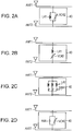
- variable reactance circuit 40 Several examples of configurations of the variable reactance circuit 40 are illustrated in FIG. 2 .
- variable reactance capacitor 40 In an example of the variable reactance capacitor 40 illustrated in FIG. 2A , a coil L41 and a variable capacitor VC42 are connected in parallel with each other. In an example of the variable reactance circuit 40 illustrated in FIG. 2B , the coil L41 and the variable capacitor VC42 are connected in series with each other. In the examples illustrated in FIG. 2A and FIG. 2B , the value of the variable capacitor VC42 is controlled using the control unit 30 to determine a reactance between the antennas.
- variable reactance circuit 40 illustrated in FIG. 2C , three cols L42 respectively having different inductances are respectively connected to respective switches constituting a switch group SW41.
- the conductive state of each of the switches constituting the switch group SW4i is controlled using the control unit 30 to determine the reactance between the antennas.
- variable reactance circuit 40 illustrated in FIG. 2D
- a resistor R41 and the variable capacitor VC42 are connected in parallel with each other.
- the value of the variable capacitor VC42 is controlled using the control unit 30 to determine the reactance between the antennas.
- the control unit 30 adaptively controls the variable reactance circuit 40 on the basis of the power value P61 sent from the power measuring unit 61 such that the amount of coupling between the antennas ANT1 and ANT2 is typically maintained low.
- the above mentioned control is repetitively performed at relatively short time intervals so as to obtain a favorable reactance between the antennas conforming to an environment in which the above mentioned radio communication device is used. The control performed using the control unit 30 will be described later.
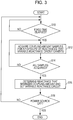
- FIG. 3 is a diagram illustrating an example of a flowchart indicating the contents of the control performed using the above mentioned radio communication device. Processes in the flowchart are mainly executed using the control unit 30.
- the processes at steps S12 to S16 are repetitively executed at fixed time intervals until the power source of the radio communication device is turned OFF (step S18). That is, when a fixed time has elapsed from execution of the previous control (YES at step S10), the processes at step S12 and succeeding steps are again executed.
- the control unit 30 acquires samples of the coupling amount for a plurality of reactances that the variable reactance circuit 40 may exhibit, that is, for reactances within an adjustable range (step S12).
- the inter-antenna coupling amount is the power value P61 which is sent from the power measuring unit 61.
- the variable reactance circuit 40 is configured as illustrated in FIG.
- control unit 30 acquires the power value P61 as a sample of the coupling amount for each of a plurality of capacitances that the variable capacitor VC42 may exhibit. When all the samples have been acquired, the process proceeds to step S16 (step S14).
- the control unit 30 determines a reactance (in the example in FIG. 2A , a capacitance of the variable capacitor VC42) at which the coupling amount is minimized in the plurality of coupling amount samples which have been acquired at step S12. Then, the control unit 30 sets the variable reactance circuit 40 such that the determined reactance may be obtained. The reactance so determined is maintained until the next control is started.
- a reactance in the example in FIG. 2A , a capacitance of the variable capacitor VC42
- a time interval at which the control is executed (the fixed time at step S10) be short enough to immediately cope with a change in environment in which the radio communication device is used.
- the radio communication device communicates with another communication device such as, for example, a base station on the basis of the FDD system. That is, the radio communication device receives a desired signal having the radio frequency fR as the center frequency in reception and transmits a radio signal having the radio frequency fT as the center frequency in transmission.
- data reception is performed via the both antennas ANT1 and ANT2 and data transmission is performed via the antenna ANT2.
- a part (a component) of a transmit signal which has been transmitted via the antenna ANT2 is absorbed into a reception system of the antenna ANT1 in such a manner that it is airborne and absorbed into the reception system of the antenna ANT1 and/or it is propagated to the reception system of the antenna ANT1 through an internal substrate or the like.
- the power value of the signal component so absorbed corresponds to the inter-antenna coupling amount.
- the duplexer 51 extracts a transmit frequency component from a receive signal which has been received using the reception system of the antenna ANT1 and the power measuring unit 61 measures the power value P61 of the component. Each power value P61 so measured is sent to the control unit 30 each time as the coupling amount. Therefore, in the above mentioned radio communication device, the coupling amount may be calculated using a simple configuration including only the duplexers and the power measuring unit in FDD-based communication.
- the control unit 30 adaptively controls the variable reactance circuit 40 at a fixed time interval. For example, it is assumed that the user has changed the manner of carrying a portable terminal serving as the radio communication device. In the above mentioned situation, the control (see FIG. 3 ) is repetitively performed at a relatively short time interval, so that the respective processes illustrated in FIG. 3 are again executed immediately after the user has changed the manner of carrying the radio communication device. As a result, the variable reactance circuit 40 is reset so as to immediately obtain an optimum reactance conforming to the freshly taken manner of carrying the radio communication device.
- the above mentioned radio communication device includes at least one transmit antenna and at least two receive antennas to perform FDD-based communication.
- the transmit frequency component is extracted from the receive signal which has been received using the reception system and the power value of the component is obtained as the coupling amount.
- the sample of the coupling amount for each of the plurality of reactances which may be exhibited between the antennas is acquired at fixed time intervals to adaptively determine each optimum reactance.
- the coupling amount to be controlled is obtained using the simple configuration only including the duplexers and the power measuring unit, so that effective control of the inter-antenna coupling amount may be realized.
- the radio communication device according to the second embodiment is configured so as to effectively reduce the inter-antenna coupling amount as in the case with the radio communication device according to the first embodiment.
- the radio communication device according to the second embodiment is different from that of the first embodiment in that it is configured to increase the accuracy of control.
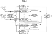
- FIG. 4 is a block diagram illustrating an example of a configuration of the above mentioned radio communication device according to the second embodiment.
- the radio communication device illustrated in FIG. 4 differs from that in FIG. 1 in that another power measuring unit 62 is added.
- the power measuring unit 62 (a second power measuring unit) measures the power of a transmit signal (the radio frequency fT) which has been transmitted from the transmit signal processing unit 20 and sends a measured power value P62 (a second power) to the control unit 30.
- the control unit 30 calculates a ratio of the power value P61 which has been measured using the power measuring unit 61 to the power value P62 which has been measured using the power measuring unit 62 (P61/P62) as the inter-antenna coupling amount of the above mentioned radio communication device.
- the contents of control executed using the control unit 30 is the same as that illustrated in FIG. 3 .
- the coupling amount is obtained simply by using the absolute value of the power value P61 (see FIG. 1 ) of the transmit frequency component of the receive signal which has been received using the reception system of the antenna ANT1 without taking the level of a transmit signal into consideration. Therefore, for example, if the power value P61 which is sent to the control unit 30 is fixed, the same result of control will be obtained regardless of a change in level of the transmit signal. However, in general, it is thought that the higher the level of a transmit signal transmitted via a transmit antenna is, the higher the level of a signal which is absorbed via a receive antenna is. Therefore, it is preferable to take the transmit power into consideration in calculation of the coupling amount. From the above mentioned viewpoint, in the above mentioned radio communication device, the magnitude of the level of the transmit signal which is transmitted via the antenna ANT2 is taken into consideration to calculate the ratio of the power value P61 to the power value P62 as the coupling amount.
- the coupling amount to be controlled may be obtained using a simple configuration including only the duplexers and the power measuring units, so that effective control of the inter-antenna coupling amount may be realized.
- the configuration of antennas is not limited to those as illustrated in FIG. 1 and FIG. 4 .
- the present art may be readily applicable to configurations including three or more antennas on the basis of the above mentioned embodiments.
- FIG. 5 is a block diagram illustrating an example of a configuration of a radio communication device according to an altered example of the first embodiment.
- the configuration of the radio communication device illustrated in FIG. 5 differs from that illustrated in FIG. 1 in that an antenna ANT3 for reception is added.
- a duplexer 53 extracts a transmit frequency component from a receive signal which has been received using a reception system of the antenna ANT3 and a power measuring unit 63 measures a power value P63 of the component.
- Each power value P63 is sent to the control unit 30 each time as an amount of coupling between the antennas ANT1 and ANT3.
- the reactance of a variable reactance circuit 41 which is disposed between the antennas ANT1 and ANT3 is set on the basis of the coupling amount so sent.
- the examples of the radio communication device which includes one receive antenna (the antenna ANT1) and one transmit/receive antenna (the antenna ANT2) have been described.
- the configuration of antennas is not limited to the above.
- the receive signal which is received via the antenna ANT2 has no influence on the control executed using the control unit 30.
- the radio communication device needs only have an antenna configuration including at least one receive signal and at least one transmit antenna.
- the radio communication device may be, for example, user equipment (UE) that performs radio communication with a base station.
- the radio communication device includes at least one transmit antenna and at least two receive antennas and performs FDD-based communication with a base station.
- UE user equipment
- the radio communication device includes at least one transmit antenna and at least two receive antennas and performs FDD-based communication with a base station.
- correlation between two receive antennas be low for a desired signal to be received from a mate communication device (for example, a base station) (that is, the inter-antenna correlation coefficient is low).
- the above mentioned radio communication device is configured to reduce the inter-antenna correlation coefficient.
- a reflection component of a transmit signal which has been transmitted via the transmit antenna and a signal component which is included in a signal transmitted via one antenna and is received via another antenna are utilized in calculation of the inter-antenna correlation coefficient.
- the two-terminal pair network in which two antennas ANT1 and ANT2 serve as input and output ports is imagined, the two-terminal pair network is expressed by S parameters as follows.
- the coefficient pe of correlation between two antennas ANT1 and ANT2 may be calculated using the following expression on the basis of the above mentioned approximate expression (the numerical formula 1).
- the coefficient of correlation between two antennas ANT1 and ANT2 is calculated using the following numerical formula 2.
- the antennas ANT1 and ANT2 are almost the same as each other in configuration and are disposed on a substrate of the radio communication device in symmetry.
- FIG. 6 is a block diagram illustrating an example of a configuration of the radio communication device according to the third embodiment.
- the radio communication device illustrated in FIG. 6 differs from the device illustrated in FIG. 4 in that a directional coupler 82 and a power measuring unit 72 are added and a control unit 31 is included in place of the control unit 30.
- the directional coupler 82 is installed on the transmission system and sends a signal component reflected from the antenna ANT2 in a transmit signal to the power measuring unit 72.
- the power measuring unit 72 (a third power measuring unit) measures a power value 72 (a third power) of the reflection signal component and sends the control unit 31 the measured power value 72.
- the measuring unit 62 measures a power value 62 of a transmit signal (the radio frequency fT) sent from the transmit signal processing unit 20 and sends the control unit 31 the measured power value P62.
- the power measuring unit 61 is installed to measure a power value 61 of a component (a component of a transmit signal transmitted via the antenna ANT2) of the radio frequency fT in a receive signal received using the reception system of the antenna ANT1.
- the power value P61 which has been measured using the power measuring unit 61 is sent to the control unit 31.
- the control unit 31 calculates the inter-antenna correlation coefficient on the basis of the power values P61, P62 and P72 which are respectively sent from the power measuring units 61, 62 and 72.
- the control unit 31 calculates the reflection coefficient (S11) of the antenna ANT2 by obtaining a ratio P72/ P62 and then calculates the coefficient of transmission from the antenna ANT2 to the antenna ANT1 by obtaining a ratio P61/P62.
- the control unit 31 calculates the correlation coefficient pe on the basis of the above numerical formula 2.
- FIG. 7 is a diagram illustrating an example of a flowchart indicating the contents of the control performed using the above mentioned radio communication device. Incidentally, processes of the flowchart are mainly executed using the control unit 31.
- steps S22 to S26 are repetitively executed at fixed time intervals until the power source of the radio communication device is turned OFF (step S28).
- control unit 31 acquires samples of the correlation coefficient ⁇ e for a plurality of reactances that the variable reactance circuit 40 may exhibit, that is, for reactances within an adjustable range (step S22).
- the inter-antenna correlation coefficient pe is calculated on the basis of the power values P61, P62 and P72 as described above.
- the control unit 31 calculates the correlation coefficient pe for each of a plurality of capacitances that the variable capacitor VC 42 may exhibit and acquires a plurality of samples of the correlation coefficient. When all the samples have been acquired, the process proceeds to step S26 (step S24).
- the control unit 31 determines a reactance (in the example in FIG. 2A , a capacitance of the variable capacitor VC42) at which the correlation coefficient is minimized in the plurality of correlation coefficient samples which have been acquired at step S22. Then, the control unit 31 sets the variable reactance circuit 40 such that the determined reactance may be obtained. The reactance so determined is maintained until the next control is started.
- a reactance in the example in FIG. 2A , a capacitance of the variable capacitor VC42
- a time interval at which each control is executed (the fixed time at step S0) be short enough to immediately cope with a change in environment in which the radio communication device is used.
- the radio communication device performs FDD-based communication with another communication device such as, for example, a base station. That is, the radio communication device receives a desired signal having the radio frequency fR as the center frequency in reception and transmits a radio signal having the radio frequency fT as the center frequency in transmission. In addition, signal reception is performed via the both antennas ANT1 and ANT2 and signal transmission is performed via the antenna ANT2. In signal reception and/or transmission, the radio communication device acquires the transmit power value (P62) of the signal transmitted via the antenna ANT2, the power value (P72) of the signal reflected from the antenna ANT2, and the power value (P61) of the transmit frequency component which is extracted from the receive signal which has been received using the reception system of the antenna ANT1.
- the radio communication device acquires the transmit power value (P62) of the signal transmitted via the antenna ANT2, the power value (P72) of the signal reflected from the antenna ANT2, and the power value (P61) of the transmit frequency component which is extracted from the receive signal which has been
- the control unit 31 calculates the inter-antenna correlation coefficient pe on the basis of the acquired power values (P61, P62 and P72). Therefore, in the above mentioned radio communication device, the inter-antenna correlation coefficient may be calculated using a simple configuration including the duplexers and the power measuring units when FDD-based communication is performed.
- the control unit 31 adaptively controls the variable reactance circuit 40 at fixed time intervals. For example, it is assumed that the user has changed the manner of carrying a portable terminal serving as the radio communication device.
- the control is repetitively performed at relatively short time intervals, so that the respective processes illustrated in FIG. 7 are again executed immediately after the manner that the user carries the radio communication device has been changed.
- the variable reactance circuit 40 is reset so as to immediately obtain an optimum reactance conforming to the freshly taken manner of carrying the device.
- the above mentioned radio communication device includes at least one transmit antenna and at least two receive antennas to perform FDD-based communication.
- the inter-antenna correlation coefficient is calculated on the basis of the power values obtained from the transmission system and the reception system. Then, a sample of the inter-antenna correlation coefficient for each of a plurality of reactances which may be exhibited between the antennas is acquired at fixed time intervals to adaptively determine an optimum reactance.
- the correlation coefficient to be controlled is obtained using a simple configuration only including the duplexers and the power measuring units, so that effective control of the inter-antenna correlation coefficient may be realized.
- the radio communication device according to the fourth embodiment is configured so as to effectively reduce the inter-antenna correlation coefficient as in the case with the radio communication device according to the third embodiment.
- the radio communication device according to the fourth embodiment is different from that of the third embodiment in that it is configured to increase the accuracy in control.
- the device according to the fourth embodiment is configured to calculate the reflection coefficient of the antenna ANT1 unlike the device in the third embodiment. Therefore, as will be described later, a local oscillator, a power measuring unit and the like used to measure the reflection power of a reflection signal reflected from the antenna ANT1 are added unlike the configuration of the third embodiment.
- FIG. 8 is a block diagram illustrating an example of a configuration of the above mentioned radio communication device.
- the radio communication device illustrated in FIG. 8 differs from that illustrated in FIG. 6 in that a power measuring unit 71, a power measuring unit 73, a directional coupler 81 and a local oscillator 90 are freshly added.
- the local oscillator 90 generates a signal (a first radio signal) of a radio frequency which is the same as the transmit frequency fT (the second radio frequency) of the antenna ANT2 and sends the generated signal to the antenna ANT1 via the duplexer 51.
- the power measuring unit 73 (a fourth power measuring unit) measures the power of the radio signal which is generated using the local oscillator 90 and sends a measured power value P73 (a fourth power) to the control unit 31.
- the directional coupler 81 takes out the reflection signal reflected from the antenna ANT1 for the radio signal which is sent from the local oscillator 90 and the power measuring unit 71 (a fifth power measuring unit) measures the reflection power of the reflection signal.
- the measured reflection power P71 (a fifth power) is sent to the control unit 31.
- the control unit 31 calculates the correlation coefficient on the basis of the power values P61, P62, P72, P71 and P73 which are respectively sent from the power measuring units 61, 62, 72, 71 and 73.
- the fourth embodiment is the same as the third embodiment in that, first, the control unit 31 calculates the reflection coefficient (S11) of the antenna ANT2 by obtaining the ratio P72/P62 and then calculates the coefficient (S21) of transmission from the antenna ANT2 to the antenna ANT1 by obtaining the ratio P61/P62. In addition to the above mentioned calculation, in the fourth embodiment, the control unit 31 calculates the reflection coefficient (S22) of the antenna ANT1 by obtaining a ratio P71/P73. After calculation of values of the S parameters, the control unit 31 calculates the correlation coefficient pe on the basis of the above mentioned numerical formula 2.
- the contents of control performed using the control unit 31 is the same as that of the example illustrated in FIG. 7 .
- the local oscillator and the power measuring units used to calculate the reflection power of the reflection signal reflected from the antenna ANT1 are installed on the reception system of the antenna ANT1 so as to calculate the reflection coefficient (S22) of the antenna ANT1. Therefore, the accuracy in calculation of the correlation coefficient pe is more increased than that attained in the third embodiment and hence a reactance between the antennas may be more appropriately set.
- the correlation coefficient pe is calculated on the basis of the numerical formula 2 in which the phase of each S parameter is not taken into consideration
- the accuracy in calculation of the correlation coefficient pe may be more increased by calculating it by taking the phase of each S parameter into consideration (that is, on the basis of the numerical formula 1).
- the phase of the coefficient (S21) of transmission from the antenna ANT2 to the antenna ANT1 is taken into consideration, it is preferable to include the configuration which is illustrated in FIG. 9 in the control unit 31 when the configuration (the third embodiment) illustrated in FIG. 6 is used as a base.
- an adder 35, a power measuring unit 36 and a phase detection unit 37 are included in the control unit 31.
- the adder 35 adds a transmit signal of a radio frequency fT sent from the transmit signal processing unit 20 and a signal component (that is, a signal component extracted using the duplexer 51) of a transmit frequency fT which is extracted from a receive signal received using the reception system of the antenna ANT1 to generate an addition signal.
- the power measuring unit 36 measures a power value P36 of the addition signal from the adder.
- the phase detection unit 37 calculates a difference in phase between the transmit signal from the transmit signal processing unit 20 and the signal which is extracted using duplexer 51 on the basis of the input power values (P61, P62 and P36).
- the principle of calculation of a phase difference is as follows. That is, assuming that the transmit signal from the transmit signal processing unit 20 is A, the signal extracted using the duplexer 51 is B, and the signal added using the adder 35 is A+B, a square value of the absolute value of each signal level (voltage) may be regarded as a power.
- the phase detection unit 37 calculates square values (
- phase of the reflection coefficient (S 11) of the antenna ANT2 is considered.
- variable inductance circuit 40 is included as an object to be controlled using the control unit.
- control unit is configured to control such that both the inter-antenna coupling amount and the inter-antenna correlation coefficient may have as favorable values as possible.
- an object to be controlled is not one of the coupling amount and the correlation coefficient and is an index value (which will be described later) which is calculated by weighting each of the coupling amount and the correlation coefficient.
- the configuration of the radio communication device according to the fifth embodiment is the same as the configurations, for example, illustrated in FIG. 6 and FIG. 8 and is different from them in the contents of control to be executed.
- FIG. 10 is a diagram illustrating an example of a flowchart indicating the contents of the control to be executed using the above mentioned radio communication device. Processes of the flowchart are executed mainly using the control unit 31 illustrated in FIG. 6 .
- step S40 the processes at steps S32 to S38 are repetitively executed at fixed time intervals until the power source of the radio communication device is turned OFF. That is, when a fixed time has elapsed from execution of the previous control (YES at step S30), the processes at step S32 and succeeding steps are again executed.
- the control unit 31 acquires samples of the coupling amount and the correlation coefficient pe respectively for a plurality of reactances that the variable reactance circuit 40 may exhibit, that is, for reactances within an adjustable range (step S32).
- the inter-antenna coupling amount corresponds to the power value P61 which is sent from the power measuring unit 61.
- the inter-antenna correlation coefficient pe is calculated on the basis of the power values P61, P62 and P72 as described above.
- the control unit 31 calculates the inter-antenna coupling amount and the inter-antenna correlation coefficient pe for each of a plurality of capacitances that the variable capacitor VC 42 may exhibit and acquires a plurality of samples of each of the inter-antenna coupling amount and the inter-antenna correlation coefficient pe.
- step S36 When the index values have been calculated for all the samples, the process proceeds to step S38 (step S36).
- the control unit 31 determines a reactance (in the example in FIG. 2A , a capacitance of the variable capacitor VC42) at which the index value is minimized in the index values of the plurality of samples which have been calculated at step S34. Then, the control unit 31 sets the variable reactance circuit 40 such that the determined reactance may be obtained. The reactance so determined is maintained until the next control is started.
- a reactance in the example in FIG. 2A , a capacitance of the variable capacitor VC42
- a time interval at which the control is executed (the fixed time at step S30) be short enough to immediately cope with a change in environment in which the radio communication device is used.
- the control is executed on the basis of the index values which are calculated by weighting each of the inter-antenna coupling amount and the inter-antenna correlation coefficient, so that the inter-antenna coupling amount and the inter-antenna correlation coefficient have the smallest possible values.
- a value of weighting is made variable, appropriate control conforming to the requirements (for example, the requirements as to whether importance is attached to the coupling performance or the correlation performance) to the radio communication device may become possible.
Landscapes
- Engineering & Computer Science (AREA)
- Computer Networks & Wireless Communication (AREA)
- Signal Processing (AREA)
- Transceivers (AREA)
- Variable-Direction Aerials And Aerial Arrays (AREA)
- Details Of Aerials (AREA)
Claims (14)
- Dispositif de radiocommunication pour exécuter une communication sur la base d'un duplex à répartition en fréquence, le dispositif de radiocommunication comprenant :une première antenne (ANTI) ;une deuxième antenne (ANT2) ;un premier récepteur (11) pour recevoir un premier signal radiofréquence (fR) via la première antenne ;un circuit à réactance variable (40) étant connecté à la première antenne et à la deuxième antenne ; et caractérisé par :un deuxième récepteur (12) pour recevoir le premier signal radiofréquence via la deuxième antenne ; etun transmetteur (21) pour transmettre un deuxième signal radiofréquence (fT) via la deuxième antenne qui reçoit le premier signal radiofréquence ;une unité de mesure de puissance (61) agencée pour mesurer une première puissance (P61) d'une composante du deuxième signal radiofréquence dans un signal reçu qui a été reçu via la première antenne ;et une unité de commande (30, 31) agencée pour calculer une quantité de couplage entre la première antenne et la deuxième antenne sur la base de la première puissance, et pour commander de façon adaptative le circuit à réactance variable à des intervalles de temps fixes, de manière à abaisser la quantité de couplage entre les antennes.
- Dispositif de radiocommunication selon la revendication 1, comprenant en outre une deuxième unité de mesure de puissance (62) pour mesurer une deuxième puissance (P62) d'un signal d'envoi de la deuxième antenne (ANT2).
- Dispositif de radiocommunication selon la revendication 2, dans lequel l'unité de commande (30) commande la réactance sur la base de la première puissance mesurée (P61) et de la deuxième puissance mesurée (P62).
- Dispositif de radiocommunication selon la revendication 2, comprenant en outre une troisième unité de mesure de puissance (72) pour mesurer une troisième puissance (P72) d'un signal de réflexion provenant de la deuxième antenne (ANT2).
- Dispositif de radiocommunication selon la revendication 4, dans lequel l'unité de commande (31) commande la réactance sur la base de la première puissance mesurée (P61), de la deuxième puissance mesurée (P62) et de la troisième puissance mesurée (P72).
- Dispositif de radiocommunication selon la revendication 4, comprenant en outre un oscillateur local (90) pour générer un premier signal radio, une quatrième unité de mesure de puissance (73) pour mesurer une quatrième puissance (P73) du premier signal radio et une cinquième unité de mesure de puissance (71) pour mesurer une cinquième puissance (P71) d'une composante de réflexion de la première antenne au premier signal radio.
- Dispositif de radiocommunication selon la revendication 6, dans lequel l'unité de commande (31) commande la réactance sur la base de la première puissance mesurée (P61), de la deuxième puissance mesurée (P62), de la troisième puissance mesurée (P72), de la quatrième puissance mesurée (P73) et de la cinquième puissance mesurée (P71).
- Procédé de commande d'un dispositif de radiocommunication pour l'exécution d'une communication sur la base d'un duplex à répartition en fréquence, le procédé comprenant :la réception premier signal radiofréquence (fR) via une première antenne (ANT1) ; et caractérisé par les étapes consistant à :recevoir le premier signal radiofréquence via la deuxième antenne (ANT2) ;transmettre un deuxième signal radiofréquence (fT) via la deuxième antenne qui reçoit le premier signal radiofréquence ;mesurer une première puissance (P61) d'une composante du deuxième signal radiofréquence dans un signal reçu qui a été reçu via la première antenne ;calculer une quantité de couplage entre la première antenne et la deuxième antenne sur la base de la première puissance ; etcommander, à des intervalles de temps fixes, une réactance entre la première antenne et la deuxième antenne de manière à abaisser la quantité de couplage entre les antennes.
- Procédé selon la revendication 8, comprenant en outre la mesure d'une deuxième puissance (P62) d'un signal d'envoi de la deuxième antenne (ANT2).
- Procédé selon la revendication 9, dans lequel l'étape de commande effectue la commande de la réactance sur la base de la première puissance mesurée (P61) et de la deuxième puissance mesurée (P62).
- Procédé selon la revendication 9, comprenant en outre la mesure d'une troisième puissance (P72) d'un signal de réflexion provenant de la deuxième antenne (ANT2).
- Procédé selon la revendication 11, dans lequel l'étape de commande effectue la commande de la réactance sur la base de la première puissance mesurée (P61), de la deuxième puissance mesurée (P62) et de la troisième puissance mesurée (P72).
- Procédé selon la revendication 11, comprenant en outre la génération d'un premier signal radio du deuxième signal radiofréquence à la première antenne, et la mesure d'une quatrième puissance (P73) du premier signal radio et d'une cinquième puissance (P71) d'une composante de réflexion à partir de la première antenne au premier signal radio.
- Procédé selon la revendication 13, dans lequel l'étape de commande effectue la commande de la réactance sur la base de la première puissance mesurée (P61), de la deuxième puissance mesurée (P62), de la troisième puissance mesurée (P72), de la quatrième puissance mesurée (P73) et de la cinquième puissance mesurée (P71).
Applications Claiming Priority (1)
| Application Number | Priority Date | Filing Date | Title |
|---|---|---|---|
| JP2009262672A JP5463868B2 (ja) | 2009-11-18 | 2009-11-18 | 無線通信装置、信号処理方法 |
Publications (2)
| Publication Number | Publication Date |
|---|---|
| EP2326018A1 EP2326018A1 (fr) | 2011-05-25 |
| EP2326018B1 true EP2326018B1 (fr) | 2017-03-29 |
Family
ID=43466919
Family Applications (1)
| Application Number | Title | Priority Date | Filing Date |
|---|---|---|---|
| EP10191219.4A Not-in-force EP2326018B1 (fr) | 2009-11-18 | 2010-11-15 | Dispositif de communication radio avec corrélation d'antennes réduite et procédé de commande du dispositif de communication radio |
Country Status (3)
| Country | Link |
|---|---|
| US (1) | US8670338B2 (fr) |
| EP (1) | EP2326018B1 (fr) |
| JP (1) | JP5463868B2 (fr) |
Families Citing this family (21)
| Publication number | Priority date | Publication date | Assignee | Title |
|---|---|---|---|---|
| US10361480B2 (en) | 2012-03-13 | 2019-07-23 | Microsoft Technology Licensing, Llc | Antenna isolation using a tuned groundplane notch |
| GB2500209B (en) | 2012-03-13 | 2016-05-18 | Microsoft Technology Licensing Llc | Antenna isolation using a tuned ground plane notch |
| US10096910B2 (en) * | 2012-06-13 | 2018-10-09 | Skycross Co., Ltd. | Multimode antenna structures and methods thereof |
| US9531418B2 (en) | 2012-08-07 | 2016-12-27 | Google Technology Holdings LLC | Tunable inter-antenna isolation |
| JP5762377B2 (ja) | 2012-09-28 | 2015-08-12 | 太陽誘電株式会社 | インピーダンス整合回路およびアンテナシステム |
| JP2014112824A (ja) * | 2012-10-31 | 2014-06-19 | Murata Mfg Co Ltd | アンテナ装置 |
| CN103812540B (zh) * | 2012-11-12 | 2017-06-27 | 华为技术有限公司 | 阵列天线及发射接收信号方法、装置 |
| CN104823325B (zh) * | 2012-11-12 | 2019-04-02 | 安施天线公司 | 用于分集应用的使用相关性管理的模态天线 |
| WO2014100989A1 (fr) * | 2012-12-26 | 2014-07-03 | 华为技术有限公司 | Système d'antenne |
| US9300342B2 (en) * | 2013-04-18 | 2016-03-29 | Apple Inc. | Wireless device with dynamically adjusted maximum transmit powers |
| US20150116162A1 (en) * | 2013-10-28 | 2015-04-30 | Skycross, Inc. | Antenna structures and methods thereof for determining a frequency offset based on a differential magnitude |
| US9791490B2 (en) | 2014-06-09 | 2017-10-17 | Apple Inc. | Electronic device having coupler for tapping antenna signals |
| CN106935971B (zh) | 2015-12-29 | 2021-02-09 | 华为技术有限公司 | 天线和通信设备 |
| JP6865072B2 (ja) * | 2017-03-13 | 2021-04-28 | 株式会社パナソニックシステムネットワークス開発研究所 | アンテナ装置及びアンテナ装置を備えた電子機器 |
| KR102464946B1 (ko) * | 2018-01-31 | 2022-11-09 | 삼성전자주식회사 | 안테나에 대한 반사계수를 결정하기 위한 장치 및 방법 |
| KR102427925B1 (ko) | 2018-03-05 | 2022-08-02 | 삼성전자주식회사 | 안테나를 통해 출력된 신호에 기반하여 결정된 외부 객체와의 거리에 따라, 지정된 기능을 수행하는 전자장치 및 방법 |
| US10826570B2 (en) | 2018-05-31 | 2020-11-03 | Skyworks Solutions, Inc. | Apparatus and methods for multi-antenna communications |
| DE102019124713B4 (de) * | 2018-11-27 | 2025-08-14 | Samsung Electronics Co., Ltd. | Vorrichtungen und Verfahren zur Steuerung einer Exposition gegenüber drahtloser Kommunikation |
| KR102703778B1 (ko) * | 2019-07-12 | 2024-09-04 | 삼성전자주식회사 | 안테나 어레이를 이용하여 외부 객체를 탐지하기 위한 전자 장치 및 방법 |
| CN116418376A (zh) * | 2021-12-29 | 2023-07-11 | 中兴通讯股份有限公司 | 天线解耦方法、电子设备和计算机可读存储介质 |
| US12477483B2 (en) * | 2023-07-27 | 2025-11-18 | Qualcomm Incorporated | Coherent uplink MIMO |
Family Cites Families (12)
| Publication number | Priority date | Publication date | Assignee | Title |
|---|---|---|---|---|
| JPH09312587A (ja) * | 1996-05-22 | 1997-12-02 | Sony Corp | 無線通信装置 |
| US6141539A (en) * | 1999-01-27 | 2000-10-31 | Radio Frequency Systems Inc. | Isolation improvement circuit for a dual-polarization antenna |
| US6920315B1 (en) * | 2000-03-22 | 2005-07-19 | Ericsson Inc. | Multiple antenna impedance optimization |
| JP4137560B2 (ja) * | 2002-08-29 | 2008-08-20 | 国立大学法人 奈良先端科学技術大学院大学 | 受信装置 |
| JP2004254111A (ja) | 2003-02-20 | 2004-09-09 | Sanyo Electric Co Ltd | アダプティブアレイ無線通信装置、アンテナ相関表示方法、アンテナ相関調整方法、アンテナ相関表示プログラム、およびアンテナ相関調整プログラム |
| JP3927918B2 (ja) * | 2003-04-03 | 2007-06-13 | 株式会社東芝 | 無線通信機および無線通信方法 |
| JP4268152B2 (ja) * | 2005-06-02 | 2009-05-27 | 富士通株式会社 | アンテナ自動整合装置 |
| US7801556B2 (en) | 2005-08-26 | 2010-09-21 | Qualcomm Incorporated | Tunable dual-antenna system for multiple frequency band operation |
| JP4542980B2 (ja) | 2005-10-31 | 2010-09-15 | 株式会社東芝 | 無線装置 |
| JP4651110B2 (ja) * | 2006-03-07 | 2011-03-16 | 国立大学法人横浜国立大学 | 無線受信用小型携帯端末装置 |
| US7965990B2 (en) * | 2007-12-06 | 2011-06-21 | Motorola Mobility, Inc. | Wireless backhaul power amplification using fourier transform matricies |
| WO2009130748A1 (fr) * | 2008-04-25 | 2009-10-29 | パナソニック株式会社 | Dispositif radio mobile |
-
2009
- 2009-11-18 JP JP2009262672A patent/JP5463868B2/ja not_active Expired - Fee Related
-
2010
- 2010-11-15 EP EP10191219.4A patent/EP2326018B1/fr not_active Not-in-force
- 2010-11-17 US US12/948,728 patent/US8670338B2/en not_active Expired - Fee Related
Non-Patent Citations (1)
| Title |
|---|
| None * |
Also Published As
| Publication number | Publication date |
|---|---|
| JP2011109440A (ja) | 2011-06-02 |
| EP2326018A1 (fr) | 2011-05-25 |
| US20110116404A1 (en) | 2011-05-19 |
| JP5463868B2 (ja) | 2014-04-09 |
| US8670338B2 (en) | 2014-03-11 |
Similar Documents
| Publication | Publication Date | Title |
|---|---|---|
| EP2326018B1 (fr) | Dispositif de communication radio avec corrélation d'antennes réduite et procédé de commande du dispositif de communication radio | |
| US9281849B2 (en) | Method and apparatus for compensating for phase shift in a communication device | |
| EP3571768B1 (fr) | Antenne cadre à détection de proximité intégrée | |
| EP2933927B1 (fr) | Dispositif et procédé de suppression auto-adaptative du brouillage radiofréquence | |
| US8170510B2 (en) | Minimizing mutual coupling | |
| EP3414837B1 (fr) | Appareil et procédé de mesure d'impédance et de syntonisation adaptative d'antenne | |
| EP2667522A2 (fr) | Dispositifs électroniques, procédés et produits de programme informatique permettant de sélectionner un élément d'antenne basé sur un critère de performance de communication sans fil | |
| US9992776B2 (en) | Wireless device and radio frequency channel calibration method | |
| KR102228899B1 (ko) | 복수의 안테나들, 및 다중-입력-포트 및 다중-출력-포트 증폭기를 사용하여 무선 수신하기 위한 방법 및 디바이스 | |
| US8581791B2 (en) | Communication device and control method | |
| US10333572B2 (en) | Antenna tuner control circuit, front-end circuit and communication device | |
| US20140038662A1 (en) | Method and apparatus for compensating for phase shift in a communication device | |
| KR102416438B1 (ko) | 다중 안테나 장치에서 채널 상태를 추정하여 송수신 신호를 제어하는 방법 및 이를 이용하는 다중 안테나 장치 | |
| CN100550673C (zh) | 阵列通信系统接收链路的校准装置及方法 | |
| CN109560837B (zh) | 用于操作通过电感耦合通信的通信装置的方法和系统 | |
| US9698484B1 (en) | Method for automatically adjusting tunable passive antennas, and automatically tunable antenna array using this method | |
| US9337534B2 (en) | Method and device for radio reception using an antenna tuning apparatus and a plurality of antennas | |
| US20140256273A1 (en) | Tunable quality factor | |
| EP3967007B1 (fr) | Dispositif électronique comprenant un émetteur-récepteur permettant d'étalonner un déséquilibre i/q dans un système de communication à ondes millimétriques et son procédé de fonctionnement | |
| EP3465952B1 (fr) | Procédé et appareil d'étalonnage de réseau d'antennes à l'aide d'un récepteur embarqué | |
| CN101060354B (zh) | 一种在强干扰环境下的智能天线多通道校准方法 | |
| EP3440736B1 (fr) | Agencement d'antennes et procédé destiné à un agencement d'antennes | |
| US20260045966A1 (en) | Computation-based detuning of coupled antennas | |
| CN121152029A (zh) | 信号处理方法、装置及电子设备 |
Legal Events
| Date | Code | Title | Description |
|---|---|---|---|
| PUAI | Public reference made under article 153(3) epc to a published international application that has entered the european phase |
Free format text: ORIGINAL CODE: 0009012 |
|
| AK | Designated contracting states |
Kind code of ref document: A1 Designated state(s): AL AT BE BG CH CY CZ DE DK EE ES FI FR GB GR HR HU IE IS IT LI LT LU LV MC MK MT NL NO PL PT RO RS SE SI SK SM TR |
|
| AX | Request for extension of the european patent |
Extension state: BA ME |
|
| 17P | Request for examination filed |
Effective date: 20111121 |
|
| 17Q | First examination report despatched |
Effective date: 20150605 |
|
| REG | Reference to a national code |
Ref country code: DE Ref legal event code: R079 Ref document number: 602010041072 Country of ref document: DE Free format text: PREVIOUS MAIN CLASS: H04B0001520000 Ipc: H01Q0001520000 |
|
| RIC1 | Information provided on ipc code assigned before grant |
Ipc: H01Q 1/52 20060101AFI20160427BHEP Ipc: H04B 1/525 20150101ALI20160427BHEP |
|
| GRAP | Despatch of communication of intention to grant a patent |
Free format text: ORIGINAL CODE: EPIDOSNIGR1 |
|
| INTG | Intention to grant announced |
Effective date: 20161020 |
|
| GRAS | Grant fee paid |
Free format text: ORIGINAL CODE: EPIDOSNIGR3 |
|
| GRAA | (expected) grant |
Free format text: ORIGINAL CODE: 0009210 |
|
| AK | Designated contracting states |
Kind code of ref document: B1 Designated state(s): AL AT BE BG CH CY CZ DE DK EE ES FI FR GB GR HR HU IE IS IT LI LT LU LV MC MK MT NL NO PL PT RO RS SE SI SK SM TR |
|
| REG | Reference to a national code |
Ref country code: GB Ref legal event code: FG4D |
|
| REG | Reference to a national code |
Ref country code: CH Ref legal event code: EP |
|
| REG | Reference to a national code |
Ref country code: AT Ref legal event code: REF Ref document number: 880543 Country of ref document: AT Kind code of ref document: T Effective date: 20170415 |
|
| REG | Reference to a national code |
Ref country code: IE Ref legal event code: FG4D |
|
| REG | Reference to a national code |
Ref country code: DE Ref legal event code: R096 Ref document number: 602010041072 Country of ref document: DE |
|
| PG25 | Lapsed in a contracting state [announced via postgrant information from national office to epo] |
Ref country code: LT Free format text: LAPSE BECAUSE OF FAILURE TO SUBMIT A TRANSLATION OF THE DESCRIPTION OR TO PAY THE FEE WITHIN THE PRESCRIBED TIME-LIMIT Effective date: 20170329 Ref country code: FI Free format text: LAPSE BECAUSE OF FAILURE TO SUBMIT A TRANSLATION OF THE DESCRIPTION OR TO PAY THE FEE WITHIN THE PRESCRIBED TIME-LIMIT Effective date: 20170329 Ref country code: HR Free format text: LAPSE BECAUSE OF FAILURE TO SUBMIT A TRANSLATION OF THE DESCRIPTION OR TO PAY THE FEE WITHIN THE PRESCRIBED TIME-LIMIT Effective date: 20170329 Ref country code: NO Free format text: LAPSE BECAUSE OF FAILURE TO SUBMIT A TRANSLATION OF THE DESCRIPTION OR TO PAY THE FEE WITHIN THE PRESCRIBED TIME-LIMIT Effective date: 20170629 Ref country code: GR Free format text: LAPSE BECAUSE OF FAILURE TO SUBMIT A TRANSLATION OF THE DESCRIPTION OR TO PAY THE FEE WITHIN THE PRESCRIBED TIME-LIMIT Effective date: 20170630 |
|
| REG | Reference to a national code |
Ref country code: NL Ref legal event code: MP Effective date: 20170329 |
|
| REG | Reference to a national code |
Ref country code: AT Ref legal event code: MK05 Ref document number: 880543 Country of ref document: AT Kind code of ref document: T Effective date: 20170329 |
|
| PG25 | Lapsed in a contracting state [announced via postgrant information from national office to epo] |
Ref country code: SE Free format text: LAPSE BECAUSE OF FAILURE TO SUBMIT A TRANSLATION OF THE DESCRIPTION OR TO PAY THE FEE WITHIN THE PRESCRIBED TIME-LIMIT Effective date: 20170329 Ref country code: LV Free format text: LAPSE BECAUSE OF FAILURE TO SUBMIT A TRANSLATION OF THE DESCRIPTION OR TO PAY THE FEE WITHIN THE PRESCRIBED TIME-LIMIT Effective date: 20170329 Ref country code: RS Free format text: LAPSE BECAUSE OF FAILURE TO SUBMIT A TRANSLATION OF THE DESCRIPTION OR TO PAY THE FEE WITHIN THE PRESCRIBED TIME-LIMIT Effective date: 20170329 Ref country code: BG Free format text: LAPSE BECAUSE OF FAILURE TO SUBMIT A TRANSLATION OF THE DESCRIPTION OR TO PAY THE FEE WITHIN THE PRESCRIBED TIME-LIMIT Effective date: 20170629 |
|
| REG | Reference to a national code |
Ref country code: FR Ref legal event code: PLFP Year of fee payment: 8 |
|
| PG25 | Lapsed in a contracting state [announced via postgrant information from national office to epo] |
Ref country code: NL Free format text: LAPSE BECAUSE OF FAILURE TO SUBMIT A TRANSLATION OF THE DESCRIPTION OR TO PAY THE FEE WITHIN THE PRESCRIBED TIME-LIMIT Effective date: 20170329 |
|
| PG25 | Lapsed in a contracting state [announced via postgrant information from national office to epo] |
Ref country code: CZ Free format text: LAPSE BECAUSE OF FAILURE TO SUBMIT A TRANSLATION OF THE DESCRIPTION OR TO PAY THE FEE WITHIN THE PRESCRIBED TIME-LIMIT Effective date: 20170329 Ref country code: EE Free format text: LAPSE BECAUSE OF FAILURE TO SUBMIT A TRANSLATION OF THE DESCRIPTION OR TO PAY THE FEE WITHIN THE PRESCRIBED TIME-LIMIT Effective date: 20170329 Ref country code: RO Free format text: LAPSE BECAUSE OF FAILURE TO SUBMIT A TRANSLATION OF THE DESCRIPTION OR TO PAY THE FEE WITHIN THE PRESCRIBED TIME-LIMIT Effective date: 20170329 Ref country code: SK Free format text: LAPSE BECAUSE OF FAILURE TO SUBMIT A TRANSLATION OF THE DESCRIPTION OR TO PAY THE FEE WITHIN THE PRESCRIBED TIME-LIMIT Effective date: 20170329 Ref country code: IT Free format text: LAPSE BECAUSE OF FAILURE TO SUBMIT A TRANSLATION OF THE DESCRIPTION OR TO PAY THE FEE WITHIN THE PRESCRIBED TIME-LIMIT Effective date: 20170329 Ref country code: AT Free format text: LAPSE BECAUSE OF FAILURE TO SUBMIT A TRANSLATION OF THE DESCRIPTION OR TO PAY THE FEE WITHIN THE PRESCRIBED TIME-LIMIT Effective date: 20170329 Ref country code: ES Free format text: LAPSE BECAUSE OF FAILURE TO SUBMIT A TRANSLATION OF THE DESCRIPTION OR TO PAY THE FEE WITHIN THE PRESCRIBED TIME-LIMIT Effective date: 20170329 |
|
| PGFP | Annual fee paid to national office [announced via postgrant information from national office to epo] |
Ref country code: GB Payment date: 20170901 Year of fee payment: 8 Ref country code: FR Payment date: 20170926 Year of fee payment: 8 |
|
| PG25 | Lapsed in a contracting state [announced via postgrant information from national office to epo] |
Ref country code: IS Free format text: LAPSE BECAUSE OF FAILURE TO SUBMIT A TRANSLATION OF THE DESCRIPTION OR TO PAY THE FEE WITHIN THE PRESCRIBED TIME-LIMIT Effective date: 20170729 Ref country code: SM Free format text: LAPSE BECAUSE OF FAILURE TO SUBMIT A TRANSLATION OF THE DESCRIPTION OR TO PAY THE FEE WITHIN THE PRESCRIBED TIME-LIMIT Effective date: 20170329 Ref country code: PL Free format text: LAPSE BECAUSE OF FAILURE TO SUBMIT A TRANSLATION OF THE DESCRIPTION OR TO PAY THE FEE WITHIN THE PRESCRIBED TIME-LIMIT Effective date: 20170329 Ref country code: PT Free format text: LAPSE BECAUSE OF FAILURE TO SUBMIT A TRANSLATION OF THE DESCRIPTION OR TO PAY THE FEE WITHIN THE PRESCRIBED TIME-LIMIT Effective date: 20170731 |
|
| REG | Reference to a national code |
Ref country code: DE Ref legal event code: R097 Ref document number: 602010041072 Country of ref document: DE |
|
| PG25 | Lapsed in a contracting state [announced via postgrant information from national office to epo] |
Ref country code: DK Free format text: LAPSE BECAUSE OF FAILURE TO SUBMIT A TRANSLATION OF THE DESCRIPTION OR TO PAY THE FEE WITHIN THE PRESCRIBED TIME-LIMIT Effective date: 20170329 |
|
| PGFP | Annual fee paid to national office [announced via postgrant information from national office to epo] |
Ref country code: DE Payment date: 20170904 Year of fee payment: 8 |
|
| PLBE | No opposition filed within time limit |
Free format text: ORIGINAL CODE: 0009261 |
|
| STAA | Information on the status of an ep patent application or granted ep patent |
Free format text: STATUS: NO OPPOSITION FILED WITHIN TIME LIMIT |
|
| 26N | No opposition filed |
Effective date: 20180103 |
|
| PG25 | Lapsed in a contracting state [announced via postgrant information from national office to epo] |
Ref country code: SI Free format text: LAPSE BECAUSE OF FAILURE TO SUBMIT A TRANSLATION OF THE DESCRIPTION OR TO PAY THE FEE WITHIN THE PRESCRIBED TIME-LIMIT Effective date: 20170329 |
|
| PG25 | Lapsed in a contracting state [announced via postgrant information from national office to epo] |
Ref country code: MC Free format text: LAPSE BECAUSE OF FAILURE TO SUBMIT A TRANSLATION OF THE DESCRIPTION OR TO PAY THE FEE WITHIN THE PRESCRIBED TIME-LIMIT Effective date: 20170329 |
|
| PG25 | Lapsed in a contracting state [announced via postgrant information from national office to epo] |
Ref country code: CH Free format text: LAPSE BECAUSE OF NON-PAYMENT OF DUE FEES Effective date: 20171130 Ref country code: LI Free format text: LAPSE BECAUSE OF NON-PAYMENT OF DUE FEES Effective date: 20171130 |
|
| PG25 | Lapsed in a contracting state [announced via postgrant information from national office to epo] |
Ref country code: LU Free format text: LAPSE BECAUSE OF NON-PAYMENT OF DUE FEES Effective date: 20171115 |
|
| REG | Reference to a national code |
Ref country code: BE Ref legal event code: MM Effective date: 20171130 |
|
| REG | Reference to a national code |
Ref country code: IE Ref legal event code: MM4A |
|
| PG25 | Lapsed in a contracting state [announced via postgrant information from national office to epo] |
Ref country code: MT Free format text: LAPSE BECAUSE OF NON-PAYMENT OF DUE FEES Effective date: 20171115 |
|
| PG25 | Lapsed in a contracting state [announced via postgrant information from national office to epo] |
Ref country code: IE Free format text: LAPSE BECAUSE OF NON-PAYMENT OF DUE FEES Effective date: 20171115 |
|
| PG25 | Lapsed in a contracting state [announced via postgrant information from national office to epo] |
Ref country code: BE Free format text: LAPSE BECAUSE OF NON-PAYMENT OF DUE FEES Effective date: 20171130 |
|
| REG | Reference to a national code |
Ref country code: DE Ref legal event code: R119 Ref document number: 602010041072 Country of ref document: DE |
|
| PG25 | Lapsed in a contracting state [announced via postgrant information from national office to epo] |
Ref country code: HU Free format text: LAPSE BECAUSE OF FAILURE TO SUBMIT A TRANSLATION OF THE DESCRIPTION OR TO PAY THE FEE WITHIN THE PRESCRIBED TIME-LIMIT; INVALID AB INITIO Effective date: 20101115 |
|
| GBPC | Gb: european patent ceased through non-payment of renewal fee |
Effective date: 20181115 |
|
| PG25 | Lapsed in a contracting state [announced via postgrant information from national office to epo] |
Ref country code: CY Free format text: LAPSE BECAUSE OF NON-PAYMENT OF DUE FEES Effective date: 20170329 Ref country code: DE Free format text: LAPSE BECAUSE OF NON-PAYMENT OF DUE FEES Effective date: 20190601 Ref country code: FR Free format text: LAPSE BECAUSE OF NON-PAYMENT OF DUE FEES Effective date: 20181130 |
|
| PG25 | Lapsed in a contracting state [announced via postgrant information from national office to epo] |
Ref country code: MK Free format text: LAPSE BECAUSE OF FAILURE TO SUBMIT A TRANSLATION OF THE DESCRIPTION OR TO PAY THE FEE WITHIN THE PRESCRIBED TIME-LIMIT Effective date: 20170329 |
|
| PG25 | Lapsed in a contracting state [announced via postgrant information from national office to epo] |
Ref country code: GB Free format text: LAPSE BECAUSE OF NON-PAYMENT OF DUE FEES Effective date: 20181115 |
|
| PG25 | Lapsed in a contracting state [announced via postgrant information from national office to epo] |
Ref country code: TR Free format text: LAPSE BECAUSE OF FAILURE TO SUBMIT A TRANSLATION OF THE DESCRIPTION OR TO PAY THE FEE WITHIN THE PRESCRIBED TIME-LIMIT Effective date: 20170329 |
|
| PG25 | Lapsed in a contracting state [announced via postgrant information from national office to epo] |
Ref country code: AL Free format text: LAPSE BECAUSE OF FAILURE TO SUBMIT A TRANSLATION OF THE DESCRIPTION OR TO PAY THE FEE WITHIN THE PRESCRIBED TIME-LIMIT Effective date: 20170329 |