EP2332665A1 - Verfahren zur Behandlung eines elektrofotografischen Trägers, Verfahren zur Herstellung eines elektrofotografischen Trägers, Kernmaterial und Träger - Google Patents
Verfahren zur Behandlung eines elektrofotografischen Trägers, Verfahren zur Herstellung eines elektrofotografischen Trägers, Kernmaterial und Träger Download PDFInfo
- Publication number
- EP2332665A1 EP2332665A1 EP10193984A EP10193984A EP2332665A1 EP 2332665 A1 EP2332665 A1 EP 2332665A1 EP 10193984 A EP10193984 A EP 10193984A EP 10193984 A EP10193984 A EP 10193984A EP 2332665 A1 EP2332665 A1 EP 2332665A1
- Authority
- EP
- European Patent Office
- Prior art keywords
- carrier
- resin
- core material
- supercritical
- coating layer
- Prior art date
- Legal status (The legal status is an assumption and is not a legal conclusion. Google has not performed a legal analysis and makes no representation as to the accuracy of the status listed.)
- Withdrawn
Links
Images


Classifications
-
- B—PERFORMING OPERATIONS; TRANSPORTING
- B08—CLEANING
- B08B—CLEANING IN GENERAL; PREVENTION OF FOULING IN GENERAL
- B08B7/00—Cleaning by methods not provided for in a single other subclass or a single group in this subclass
- B08B7/0021—Cleaning by methods not provided for in a single other subclass or a single group in this subclass by liquid gases or supercritical fluids
-
- B—PERFORMING OPERATIONS; TRANSPORTING
- B01—PHYSICAL OR CHEMICAL PROCESSES OR APPARATUS IN GENERAL
- B01D—SEPARATION
- B01D11/00—Solvent extraction
- B01D11/02—Solvent extraction of solids
- B01D11/0203—Solvent extraction of solids with a supercritical fluid
-
- B—PERFORMING OPERATIONS; TRANSPORTING
- B01—PHYSICAL OR CHEMICAL PROCESSES OR APPARATUS IN GENERAL
- B01D—SEPARATION
- B01D11/00—Solvent extraction
- B01D11/02—Solvent extraction of solids
- B01D11/0288—Applications, solvents
-
- G—PHYSICS
- G03—PHOTOGRAPHY; CINEMATOGRAPHY; ANALOGOUS TECHNIQUES USING WAVES OTHER THAN OPTICAL WAVES; ELECTROGRAPHY; HOLOGRAPHY
- G03G—ELECTROGRAPHY; ELECTROPHOTOGRAPHY; MAGNETOGRAPHY
- G03G9/00—Developers
- G03G9/08—Developers with toner particles
- G03G9/10—Developers with toner particles characterised by carrier particles
- G03G9/107—Developers with toner particles characterised by carrier particles having magnetic components
- G03G9/1075—Structural characteristics of the carrier particles, e.g. shape or crystallographic structure
-
- G—PHYSICS
- G03—PHOTOGRAPHY; CINEMATOGRAPHY; ANALOGOUS TECHNIQUES USING WAVES OTHER THAN OPTICAL WAVES; ELECTROGRAPHY; HOLOGRAPHY
- G03G—ELECTROGRAPHY; ELECTROPHOTOGRAPHY; MAGNETOGRAPHY
- G03G9/00—Developers
- G03G9/08—Developers with toner particles
- G03G9/10—Developers with toner particles characterised by carrier particles
- G03G9/113—Developers with toner particles characterised by carrier particles having coatings applied thereto
- G03G9/1132—Macromolecular components of coatings
- G03G9/1135—Macromolecular components of coatings obtained otherwise than by reactions only involving carbon-to-carbon unsaturated bonds
- G03G9/1136—Macromolecular components of coatings obtained otherwise than by reactions only involving carbon-to-carbon unsaturated bonds containing silicon atoms
Definitions
- the present invention relates to recycling and reutilizing core materials forming carriers of two-component electrostatic image developers used in, for example, electrophotography and electrostatic recording.
- Two-component dry developers used for electrophotography each contain toner and carrier particles.
- the two-component dry developers (hereinafter may be referred to simply as a "developer")
- fine toner particles are retained on relatively large particles by magnetic force generated as a result of friction between both the particles.
- the electrical fields in the latent electrostatic images attract the toner particles at a greater force than the binding force between the toner and carrier particles.
- the toner particles are attracted and attached onto the latent electrostatic images, which are then visualized.
- Carriers contained in the two-component dry developers treated by the present invention include at least core materials (i.e., magnetic particles) and a resin.
- the carrier particles are classified into a coating-type carrier in which a layer made mainly of a coating layer is formed on the surface of a relatively large magnetic particle, and a dispersion-type carrier in which relatively small magnetic particles are uniformly dispersed in a resin. Whether the coating-type carrier or the dispersion-type carrier is used is appropriately determined. In many cases, the coating-type carrier is used in practice.
- the developers are repeatedly used in image forming apparatuses while the consumed toner particles are being replenished.
- the carrier particles must frictionally charge the toner particles constantly so that the toner particles have a sufficient charge amount at a desired polarity over a long period of time.
- Examples of the proposed resins and methods include a method of crosslinking a resin containing a polycarbodiimide resin (see Japanese Patent Application Laid-Open (JP-A) No. 05-127432 ), a method of crosslinking an acrylic resin having a specific property and structure (see JP-A Nos. 05-216282 and 05-216283 ), a method of forming a coating resin having a composite crosslinked structure consisting of urethane and urea (see JP-A No. 05-197211 ), a method of using a silicone resin having a specific silane coupling agent (see JP-A No.
- the former method (method A) is exemplified by JP-A No. 06-149132 , in which spent toner particles on the carrier surface are removed by heating or washing with solvents so as to recycle core materials.
- the core materials are recycled without removing the previously coated resins.
- This method can mainly recycle carriers degraded in characteristics due to toner spent.
- the latter method is exemplified by JP-A No. 47-12286 , in which the recovered developer is heated at a high temperature of about 1,000°F for recycling.
- this method is applied to carriers coated with thermoplastic resins such as, for example, acrylic resins, not only the spent toner but also the coated resin can be removed through such thermal treatment. Even when degradation in characteristics of the carrier results from not only spent toner but also cracking, fracture and abrasion in the carrier coating resin, the treated core materials are recycled after coated again upon reuse.
- thermosetting resin (coating resin) cannot be sufficiently removed.
- the present inventors have found that, when the core materials still have the coating resin and the products of the high-temperature heating treatment, recycled carriers formed using the above core material have less desirable characteristics compared with carriers formed using virgin core materials. That is, the characteristics of developers using such recycled core materials are clearly inferior to those of developers using virgin core materials. This difference in performance is smaller when the previously coated resin is removed thoroughly. Therefore, in order for the developer characteristics of these two developers to be comparable, it is desirable that the residual core coating resin be smaller or that the removal rate of the coating resin be higher.
- the conditions of the conventional methods do not meet at the same time the goals of both removing the resin materials which are tightly bonded chemically and mechanically to the core materials and retaining desirable properties of magnetic materials.
- none of the conventional methods is applied to magnetic particles made of coating resin and metal suboxide particles having a specific crystal structure, to thereby recover the magnetic particles without inducing oxidation or reduction of the metal suboxide, breaking the crystal state thereof and degrading their magnetic characteristics. That is, magnetic materials for use in core materials are made of suboxides having a specific crystal structure, and thus, it is necessary to avoid any chemical change, for example, oxidation and/or any change in crystal structure during the recycling treatment.
- JP-A No. 05-53000 proposes decomposing the resin in water having a supercritical or subcritical state. With this method, many resins can be hydrolized or thermodecomposed to monomer units.
- thermosetting resin As to the decomposition of resins, there have been proposed a method in which a thermosetting resin is decomposed in water brought into a supercritical or subcritical state (see JP-A No. 10-24274 ), a method in which chlorine-containing plastic wastes are decomposed in supercritical water serving as a reaction medium and converted into oil (see JP-A No. 09-111249 ) and other methods. These methods are performed mainly for decomposing a lot of resin wastes for detoxification and recycling. Also, these patent literatures disclose the treatment conditions suitable for the materials to be treated.
- the present applicant has proposed methods in which a carrier composed of a magnetic material and a coating resin is treated with supercritical or subcritical water, to thereby separate the coating resin from the magnetic material (see JP-B Nos. 3847534 and 3853159 ).
- JP-B No. 3847534 uses aqueous hydrogen peroxide as a treatment liquid under supercritical or subcritical conditions.
- aqueous hydrogen peroxide as a treatment liquid under supercritical or subcritical conditions.
- the removal of the resin tends to be decreased under subcritical conditions, and also, the oxidation effects by the aqueous hydrogen peroxide greatly impair the characteristics of magnetic particles of a specific crystalline metal suboxide.
- JP-B No. 3853159 uses distilled water as a treatment liquid under supercritical or subcritical conditions.
- the removal of the resin tends to be decreased under subcritical conditions, and also, distilled water does not have such a purity that is comparable to pure water. As a result, the removal of the resin tends to be decreased by the impurities.
- thermosetting resins Although a lot of resins have been found to be decomposed under supercritical or subcritical conditions as described above, not all the resins can be decomposed.
- the " Advanced Research Project for Utilizing Supercritical Fluid” issued in 1997 by New Energy Development Organization leading "New Sunshine Project” reports on the decomposition of several thermosetting resins.
- a phenol resin As an example for the thermosetting resins, a phenol resin is reported to have a low decomposition rate after treated in supercritical water, which involves so-called charring. This also reports that other resins have different appropriate decomposition conditions.
- the inventions disclosed in JP-A Nos. 10-80674 and 10-87872 intend to separate a resin from a core material made of, for example, a fiber, and no description could be found of recycling the core material and a change in characteristics of the core material.
- none of them describes that the inventions are applied to magnetic particles made of a coating resin and metal suboxide particles having a specific crystal structure, to thereby recover the magnetic particles without inducing oxidation or reduction of the metal suboxide, breaking the crystal state thereof and degrading their magnetic characteristics.
- core materials used in electrophotographic carriers are magnetic materials having a certain particle diameter range and are highly controlled so that their shape becomes spherical as much as possible. In the above literatures, no description has been presented regarding the effects on the shape and size of the magnetic particles, which may be caused by supercritical or subcritical water.
- a first object of the present invention is to provide a method for treating an electrophotographic carrier and a method for producing an electrophotographic carrier, which can separate a two-component electrophotographic developer's carrier into a magnetic material (core material) and a coating layer (coating resin), which has previously been coated on the magnetic material firmly, without adversely affecting the characteristics of the core material.
- the obtained core material can be coated again with a coating layer and then exhibit satisfactory performances.
- the present invention aims to provide an improved separation means and a recycling method which include reliably removing the coating layer in an environmentally friendly manner without degrading the characteristics of the core material. That is, the treated core material can be recycled.
- a second object of the present invention is to provide economical treatment conditions under which a carrier coating resin can be reliably removed in an environmentally friendly manner.
- a third object of the present invention is to provide a core material whose coating layer (resin) has been removed and a carrier obtained by newly coating the core material with a coating layer.
- the present inventors performed extensive studies to achieve the above objects, and have unexpectedly found that supercritical pure water is effective to the achievement of the above objects.
- the present invention is based on the above finding obtained by the present inventors, and means for solving the existing problems are as follows.
- the method of the present invention for treating an electrophotographic carrier is a method of treating a carrier contained in a used developer with supercritical pure water, which is obtained by bringing pure water having an electrical conductivity (25°C) of 1 ⁇ S ⁇ cm or lower into a supercritical state, so that the coating resin is separated from the core material through hydrolysis and/or thermodecomposition.
- the method of the present invention has advantageous effects that the coating resin can be removed reliably and efficiently in an environmentally friendly manner and that the coating resin can be removed at a higher removal rate without degrading the core material itself.
- the method of the present invention for treating an electrophotographic carrier has an advantage effect that it attains more efficient decomposition when the supercritical pure water used for treating the carrier is obtained at 375°C or higher and 25 MPa or higher.
- the method of the present invention for treating an electrophotographic carrier has an advantageous effect that, by treating with supercritical pure water a carrier to be treated which has a core material made of at least a magnetic material and a coating resin film, the coating resin film is reliably separated from the core material of the magnetic material.
- the method of the present invention for treating an electrophotographic carrier has an advantageous effect that it can treat the carrier containing ferrite or magnetite as the magnetic material without degrading the core material itself, since ferrite or magnetite are relatively stable in supercritical pure water.
- the coating resin can be reliably separated from the carrier to be treated containing undecomposed matter in a large amount. Furthermore, the treatment can be performed with high thermal efficiency.
- the method of the present invention for producing an electrophotographic carrier is a method including separating a carrier into a core material and a coating resin by the above-described treating method; washing the core material simultaneously with or subsequent to the separating; and drying the core material.
- the core material that have conventionally been disposed of can be recycled, which realizes contribution to the protection of the global environment.
- active ingredients such as resin monomers can be recycled from the treatment liquid, which also leads to the environmental protection.
- the method of the present invention has advantageous effects that the coating resin can be completely separated from the carrier and that thermal energy can be utilized effectively. As described above, since the core material (magnetic material) whose coating resin has been separated by the method of the present invention is not degraded in characteristics, the core material can be recycled.
- the method of the present invention for treating an electrophotographic carrier includes treating, with supercritical pure water, the electrophotographic carrier (carrier to be treated) containing at least a core material and a coating layer, so that the coating layer is separated from the core material (separating step), wherein the supercritical pure water is obtained by bringing pure water having an electrical conductivity (25°C) of 1 ⁇ S ⁇ cm or lower into a supercritical state.
- the carrier contained in a developer in general, a used developer
- a developer in general, a used developer
- supercritical water pure water
- the method of the present invention for treating an electrophotographic carrier includes at least a separating step, preferably includes a washing step; and, if necessary, further includes other steps.
- the separating step is a step of treating, with supercritical pure water, an electrophotographic carrier containing at least a core material and a coating layer (coating resin), so that the coating layer is separated from the core material, wherein the supercritical pure water is obtained by bringing pure water having an electrical conductivity (25°C) of 1 ⁇ S ⁇ cm or lower into a supercritical state.
- Water used for the supercritical pure water in the present invention is pure water having an electrical conductivity (25°C) of 1 ⁇ S ⁇ cm or lower, preferably ultra pure water having an electrical conductivity (25°C) of 0.1 ⁇ S ⁇ cm or lower.
- ultra pure water having a low electrical conductivity, contains almost no impurities such as ions, and thus degrades the quality of core materials during supercritical treatment to a less extent.
- water having an electrical conductivity higher than 1 ⁇ S ⁇ cm contains impurities such as ions in a larger amount, and thus may degrade the quality of core materials during supercritical treatment.
- the effect of removing (separating) the resin becomes weak.
- aqueous hydrogen peroxide not only removes/separates the coating resin but also impairs the quality of core materials due to their oxidizing effects, which is not preferred.
- the electrical conductivity (25°C) of water is introduced as follows.
- the mixing ratio between the carrier and the fluid cannot be determined flatly.
- the mass of the fluid (pure water) is preferably three times or more greater than that of the carrier to be treated. At this mixing ratio, the coating removal can be performed satisfactorily.
- the separation treatment with supercritical pure water is preferably performed for 1 min to 90 min.
- this treatment time varies with the properties of the coating resin used and on the temperature/pressure conditions for supercritical pure water, it is preferably 1 min to 60 min, more preferably 2 min to 30 min.
- the method of the present invention for treating an electrophotographic carrier is a method of treating a carrier to be treated which has a core material and a crosslinked resin coated thereon-this resin is hardly dissolved in a solvent, etc.-in water having a supercritical state, so that the coating resin is reliably separated from the magnetic material.
- the method of the present invention for treating an electrophotographic carrier is a method of treating a carrier to be treated which has a core material made of at least a magnetic material and a silicone resin coated thereon-this coating resin (silicone resin) is not easily decomposed through combustion, etc.-in water having a supercritical state, so that the coating resin is reliably separated from the magnetic material.
- the method of the present invention for treating an electrophotographic carrier is a method of treating a carrier to be treated which has a core material made of at least a magnetic material and a coating resin film made mainly of a silicone resin-this resin is hardly separated even by various separation means such as a solvent, an acid, a base and combustion-in water having a supercritical state, so that the coating resin is reliably separated from the magnetic material.
- the form of the magnetic material-containing carriers treated by the method of the present invention is roughly classified into two types: carriers having relatively large magnetic particles and a layer made mainly of a coating resin present on the particle surfaces, and carriers containing a resin and relatively small magnetic powder homogeneously dispersed in the resin. In either carrier, the present invention is applicable.
- the magnetic materials contained in the carrier treated by the method of the present invention may be those conventionally known in the art. Examples thereof include ferromagnetic metals such as iron, cobalt and nickel; alloys such as magnetite, hematite and ferrite; and complexes formed between resins and microparticles of the above ferromagnetic metals.
- the average particle diameter of the magnetic particles is generally about 10 ⁇ m to about 1,000 ⁇ m.
- some of the magnetic materials are oxidized or hydrolyzed.
- magnetic materials that are more stable under these conditions are preferably used.
- Examples of the magnetic materials preferably treated by the method of the present invention include metal oxide magnetic materials such as ferrite and magnetite.
- Ferrite is stable in supercritical pure water and thus, can be separated without degradation of the core material itself. It may be noted, even for the materials which may be relatively easily degraded by water having a supercritical state, such degradation may be obviated by appropriately setting the conditions such as temperature, pressure, treatment time and/or additives considering the coating resin used.
- the treatment with supercritical pure water is preferably performed under non-oxidizing conditions. Also, this treatment is more preferably performed under both non-oxidizing and non-reducing conditions from the viewpoint of preventing degradation of the magnetic materials.
- the magnetic materials used for the carrier can be coated again with a resin.
- the surfaces of the core materials are mechanically frictioned with stirring, whereby attached matter can be removed more reliably.
- an ultra sonic washer may also be used, but the below-described washing step is particularly preferably performed.
- the washing step is a step of washing separated core materials with a washing liquid (water) which contains bubbles having small particle diameters.
- the water containing bubbles having small particle diameters preferably has an electrical conductivity of 10 ⁇ S ⁇ cm or lower. More preferably, the water has an electrical conductivity of 1 ⁇ S ⁇ cm or lower; i.e., contains almost no ions.
- the water used for the washing step contains a large amount of ions like tap water (electrical conductivity: higher than 10 ⁇ S ⁇ cm)
- the ions are attached during washing onto the surfaces of the core materials separated from the coating resin, potentially impairing chemical and physical characteristics of the core materials.
- the impact generated upon disruption of the bubbles separates, from the core material surfaces, the separated resin coating components, re-attached matter of fillers contained in the coating resin, and the coating resin and fillers remaining after the separation treatment.
- the resin, filler and stains present on the core material surfaces can also be removed to some extent.
- the core materials are washed under application of ultra sonic vibration, and then the supernatant is removed. And, the washing liquid, containing the treated core materials, is filtrated through aspiration.
- the washing is performed two or three times, preferably three or five times.
- the amount of the residual matter such as the separated coating resin components and fillers decreases with increasing the number of the washing treatments.
- the fillers used for controlling resistance remain on the core material surfaces, the magnetic characteristics-one important property-are decreased, which is not preferred.
- the productivity or yield is disadvantageously decreased.
- the amount of the materials remaining on the surfaces of the carrier core materials can be reduced, and also a decrease in magnetic characteristics can be prevented.
- the water from which carrier-forming resins, fillers and decomposed or dissolved matter remaining after separation and washing have been removed is supplied to a container housing and holding the developer, the amount of the materials remaining on the core material surfaces can be reduced, and also a decrease in magnetic characteristics can be prevented.
- a method of the present invention for producing an electrophotogaraphic carrier includes treating the carrier with supercritical pure water, so that its coating resin is separated from its core material through hydrolysis and/or thermodecomposition and dissolution; and washing the core material simultaneously with or subsequent to the treating; and drying the core material.
- the core materials are allowed to pass through a coarse screen, to thereby remove coarse magnetic materials having particle diameters larger than the desired particle diameter, which are formed unexpectedly or when the coating resin layer has not completely been separated; and the core materials are allowed to pass through a fine screen, to thereby remove fine magnetic materials having particle diameters smaller than the desired particle diameter, which are formed through friction and crash.
- the core materials when recycled as carrier core materials, may be mixed with virgin core materials.
- active ingredients such as resin monomers can be recycled from the treatment liquid.
- the coating resin in the method of the present invention for separating the carrier coating resin from the core material, by reducing over time decomposed and/or dissolved matter of the developer-forming materials contained in the supercritical pure water brought into contact with the carrier to be treated, the coating resin can be reliably separated from the carrier to be treated containing undecomposed matter in a large amount.
- the treatment can be performed with high thermal efficiency.
- the core materials whose coating resin has been separated are newly coated with a resin (preferably, a silicone resin) to thereby obtain carriers.
- the method of the present invention for separating the carrier coating resin from the magnetic material exhibits the same effects as described above in a reaction device composed of a container and pipes.
- the form of the magnetic material-containing carriers treated by the method of the present invention is roughly classified into two types: carriers having relatively large magnetic particles and a layer made mainly of a coating resin present on the particle surfaces, and carriers containing a resin and relatively small magnetic powder homogeneously dispersed in the resin. In either carrier, the present invention is applicable.
- the magnetic materials (core materials) contained in the carrier treated by the method of the present invention may be those conventionally known in the art. Examples thereof include ferromagnetic metals such as iron, cobalt and nickel; alloys such as magnetite, hematite and ferrite; and complexes formed between resins and microparticles of the above ferromagnetic metals.
- the average particle diameter of the magnetic particles is generally about 10 ⁇ m to about 1,000 ⁇ m.
- some of the magnetic materials are oxidized or hydrolyzed.
- magnetic materials that are more stable under these conditions are preferably used.
- the magnetic materials preferably treated by the method of the present invention include metal oxide magnetic materials such as ferrite and magnetite. It may be noted, even for the materials which may be relatively easily degraded by water having a supercritical state, such degradation may be obviated by appropriately setting the conditions such as temperature, pressure, treatment time and/or additives considering the coating resin used.
- the coating resin of the carrier in the present invention may be resins conventionally known in the art. As described above, silicone resins or modified products thereof are preferably used. Examples of such resins forming the coating layer include polyolefin resins such as polyethylenes, polypropylenes, chlorinated polyethylenes and chlorosulfonated polyethylenes; polyvinyl or polyvinylidene resins such as polystyrenes, acrylic resins (e.g., polymethyl methacylates), polyacrylonitriles, polyvinyl acetates, polyvinyl alcohols, polyvinyl butyrals, polyvinyl chlorides, polyvinyl carbazoles, polyvinyl ethers and polyvinyl ketones; vinyl chloride-vinyl acetate copolymers; silicone resins having organosiloxane bonds and modified products thereof (e.g., alkyd resin-, polyester resin-, epoxy resin- and polyurethane-modified silicone resins); fluorine-containing resin
- Silicone resins usable in the present invention may be selected from those conventionally known in the art. Examples thereof include straight silicones having only organosiloxane bonds expressed by the following formula; and silicone resins modified by alkyd, polyester, epoxy or urethane.
- R 1 represents a hydrogen atom, a C1-C4 alkyl group or a phenyl group
- R 2 and R 3 each represent a hydrogen atom, a C1-C4 alkoxy group, a phenyl group, a phenoxy group, a C2-C4 alkenyl group, a C2-C4 alkenyloxy group, a hydroxyl group, a carboxyl group, an ethylene oxide group, a glycidyl group or a group represented by the following formula.
- R 4 and R 5 each represent a hydroxyl group, a carboxyl group, a C1-C4 alkyl group, a C1-C4 alkoxy group, a C2-C4 alkeny group, a C2-C4 alkenyloxyl group, a phenyl group or a phenoxy group, and each of k, 1, m, n, o and p is an integer of 1 or greater.
- Each of the above-described substituents may have no substituent or may have a substituent such as an amino group, a hydroxyl group, a carboxyl group, a mercapto group, an alkyl group, a phenyl group, an ethylene oxide group, a glycidyl group or a halogen atom.
- the resin material may be crosslinked in the presence of a crosslinking agent through, for example, a thermal treatment.
- a thermal treatment for example, a thermal treatment.
- the coated layer of such a thermally crosslinked resin material is generally insoluble to a solvent, an acid and a base.
- the materials which are formed during the thermal treatment e.g., carbide
- the method of the present invention can reliably separate such matter from the magnetic materials, while it is difficult for the other methods to do so.
- silicone resins cured are quite difficult to remove. This is because the silicone resins are stable to various acids and bases, insoluble in solvents, and hard to decompose even by combustion.
- the silicone resins usable in the present invention may be selected from those conventionally known in the art.
- silicone resins include those commercially available from Shinetsu Silicones Co., such as KR261, KR271, KR272, KR275, KR280, KR282, KR285, KR251, KR155, KR220, KR201, KR204, KR205, KR206, SA-4, ES-1001, ES1001N, ES-1002T and KR3093; and those commercially available from Toray-Dow Corning Co., such as SR2100, SR2101, SR2107, SR2110, SR2108, SR2109, SR2115, SR2400, SR2410, SR2411, SH805, SH806A and SH840.
- Shinetsu Silicones Co. such as KR261, KR271, KR272, KR275, KR280, KR282, KR285, KR251, KR155, KR220, KR201, KR204, KR205, KR206, SA-4,
- the carriers used in the present invention may contain a conductivity-imparting material dispersed in their coating layers for the purpose of controlling the volume conductivity thereof.
- the conductivity-imparting material may be those conventionally known in the art, such as metals (e.g., iron, gold and copper), iron oxides (e.g., ferrite and magnetite) and pigments (e.g., carbon black).
- metals e.g., iron, gold and copper
- iron oxides e.g., ferrite and magnetite
- pigments e.g., carbon black
- use of fine conductive powder mixture of furnace black (one carbon black) and acetylene black can effectively control conductivity even in a small amount.
- the obtained carriers can have coating layers excellent in abrasion resistance.
- Such fine conductive particles preferably have a particle diameter of about 0.01 ⁇ m to about 10 ⁇ m, and are preferably added in an amount of 2 parts by mass to 30 parts by mass, more preferably 5 parts by mass to 20 parts by mass, per 100 parts by mass of the coating resin. Notably, there is no particular influence to the treatment in the present invention, even when materials such as the above fine conductive particles are contained in the coating resin.
- a silane coupling agent, a titanium coupling agent, or other agents may be added to the carrier coating layer, in order to improve the adhesion to core materials and the dispersibility of the conductivity-imparting material.
- silane coupling agent used in the present invention is expressed by the following general formula.
- silane coupling agents preferred are aminosilane coupling agents where Y is an amino group in the above formula, in order to obtain a developer having negative chargeability; while preferred are epoxysilane coupling agents where Y is an epoxy group in the above formula, in order to obtain a developer having positive chargeability.
- Carrier particles treated by the method of the present invention are actually recovered as a used developer, which is a mixture of carrier and toner particles.
- this mixture may be directly subjected to supercritical treatment, the toner particles are preferably separated from the carrier particles prior to the supercritical treatment, since the toner particles can be easily separated.
- an electrostatic treatment such as the blowing-off method may be performed.
- spent toner on carriers is difficult to separate therefrom.
- the spent toner may be removed at a pretreatment step prior to the supercritical treatment.
- the spent toner may be subjected to cleaning with a solvent or a thermal treatment.
- the incorporation of the toner particles does not have a considerable adverse effect on the separation of the magnetic materials from the resin materials, since the separation can be sufficiently performed even with some toner particles incorporated upon the supercritical treatment.
- supercritical pure water used for treating carrier may be appropriately prepared at a temperature of 375°C to 400°C and a pressure of 22 MPa to 30 MPa, preferably at a temperature of 380°C to 390°C and a pressure of 25 MPa to 28 MPa.
- the coating resin can be efficiently decomposed.
- the conditions are suitably determined so that the coating resin is rapidly decomposed and the magnetic materials are not degraded.
- both may preferably be adjusted as high as possible.
- the temperature is set to a high temperature of 380°C or higher, and the pressure is set to a high pressure of 25 MPa or higher.
- the coating resin in the step of separating the coating resin from the magnetic materials in carriers, it may also be sufficient for the coating resin to be partially removed. That is, when deterioration is observed only in the vicinity of the surface thereof, the removal of the resin in that portion may be sufficient.
- the extent of the decomposition can be controlled by, for example, the decomposition time.
- the rate of the coating resin removed is preferably 70% or higher, more preferably 80% or higher, most preferably 90% or higher.
- the rate of the coating resin removed is preferably higher, especially in order to stabilize the production process. This is because, especially when a mixture of treated core materials and virgin core materials is coated, the differences in the core materials may influence the performance of the resultant developer.
- the treated core materials whose coating layers have been removed to a higher extent could be treated in the same production conditions as in the virgin core materials, and thus need no particular treatments when used.
- the core materials obtained had neither coating resin nor re-attached matter of the matter separated from the core material surfaces.
- the core materials that have conventionally been disposed of can be recycled, which realizes contribution to the protection of the global environment.
- active ingredients such as resin monomers can be recycled from the treatment liquid, which also leads to the environmental protection.
- the carrier treated with supercritical pure water is subjected to a step of washing the core materials (i.e., magnetic materials) to remove matter attached thereonto, and then a drying step, the magnetic materials used for the carrier can be successfully coated again with a resin.
- core materials i.e., magnetic materials
- the surfaces of the core materials are mechanically frictioned with stirring, whereby the attached matter can be removed more reliably.
- an ultra sonic washer may also be used, but the carrier whose coating resin has been removed is particularly preferably washed with water containing bubbles having small particle diameters equal to or smaller than those of microbubbles or nanobubbles.
- the water containing bubbles having small particle diameters comparable to those of microbubbles or nanobubbles preferably has an electrical conductivity of 10 ⁇ S ⁇ cm or lower.
- the water preferably has an electrical conductivity of 1 ⁇ S ⁇ cm or lower; i.e., contains almost no ions.
- the water used for the washing step contains a large amount of ions like tap water (electrical conductivity: 10 ⁇ S ⁇ cm or higher), the ions are attached during washing onto the surfaces of the core materials separated from the coating resin, potentially impairing chemical and physical characteristics of the core materials.
- tap water electrical conductivity: 10 ⁇ S ⁇ cm or higher
- the impact generated upon disruption of the bubbles separates, from the core material surfaces, the separated resin coating components, re-attached matter of fillers contained in the coating resin, and the coating resin and fillers remaining after the separation treatment.
- the core materials are washed under application of ultra sonic vibration, and then the supernatant is removed through overflow. And, the washing liquid, containing the treated core materials, is filtrated through aspiration.
- the washing is performed two or three times, preferably three or five times.
- the amount of the residual matter such as separated coating resin components and fillers decreases with increasing the number of the washing treatments.
- the fillers used for controlling resistance remain on the core material surfaces, the magnetic characteristics-one important property-is decreased, which is not preferred.
- the method of the present invention for separating carrier core materials from coating resin thereof is a method of treating a carrier to be treated which has a core material made of at least a magnetic material and a coating resin film made mainly of a silicone resin-this resin is hardly separated even by various separation means such as a solvent, an acid, a base and combustion-in water having a supercritical state, so that the coating resin is reliably separated from the magnetic material.
- Fig. 1A illustrates the entirety of a reaction container used in the present invention
- Fig. 1B illustrates a sample to be treated (carrier) and a fluid (pure water) housed in the reaction container.
- an inner cylinder 111 of a reaction container 11, housed in a housing portion 15, contains liquid 31 and a developer 32 to be treated.
- the liquid 31 may be a solvent such as water and alcohol.
- the liquid 31 is preferably water, since supercritical or subcritical water can be easily prepared.
- bubbles having small particle diameters can be easily formed as compared with the other solvents, since water has a high surface tension.
- the reaction container 11 and the inner cylinder 111 are made of austenitic stainless steels such as SUS316.
- the austenitic stainless steels are hardly rusted, have high strength, and have no magnetism, and thus are suitable to the treatment of the developer 32 containing magnetic materials.
- the reaction container 11 measures 8.5 mm in inner diameter and 2.1 mm in thickness, and has a capacity of 109 cm 3 for housing the developer 32, etc.
- the reaction container 11 is immobilized with screws so that the inner pressure thereof is not changed.
- Fig. 2 illustrates the configuration of a separating apparatus used for the method of the present invention for treating a carrier.
- a separating apparatus 1 includes a heating device 12 which houses the reaction container 11.
- fluidized sand 33 containing alumina powder is contained in the housing portion 15 which houses the reaction container 11.
- a heater 13 for heating the housing portion 15 is provided around the housing portion 15.
- the separating apparatus 1 further includes a compressor 14 for feeding hot air 34 to the housing portion 15 and another heater 13 for heating air.
- the developer 32 is placed in the reaction container 11, which is then purged with argon or other gas, followed by pressurizing.
- a plurality of the reaction containers 11 are housed in the housing portion 15 of the heating device 12.
- the reaction container can be uniformly heated by the heating device 12 and the fluidized sand 33 circulated with the air 34.
- the reaction container 11 is placed for a predetermined period in the fluidized sand 33 whose temperature has set to a predetermined temperature.
- Supercritical water is formed at a high temperature and a high pressure in the reaction container 11, where the carriers can be separated into the resins and the core materials.
- reaction container After the predetermined heating period, the reaction container is quenched in a cooling bath containing ice, etc., and returned to the normal temperature and pressure, followed by removal of the separated core materials and other matter. In this manner, the carriers can be separated into the core materials and the coating resins.
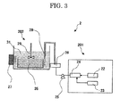
- Fig. 3 illustrates the configuration of a washer used in the method of the present invention for treating a carrier.
- the washer 2 includes a microbubble- or nanobubble-generator 201 (hereinafter referred to as a "bubble generator") and a tank 202.
- a microbubble- or nanobubble-generator 201 hereinafter referred to as a "bubble generator”
- tank 202 the tank 202.
- the bubble generator 201 includes a pressurized water-supplying section 22 (which supplies pressurized water), a pressurized air-supplying section 23 (which supplies pressurized air) and a gas-liquid mixing section 24 (which mixes the supplied water and the supplied air).
- a pressurized water-supplying section 22 which supplies pressurized water
- a pressurized air-supplying section 23 which supplies pressurized air
- a gas-liquid mixing section 24 which mixes the supplied water and the supplied air.
- the formed gas-liquid mixture is fed by a feeding pump 25 into a stock tank 26.
- the tank 202 contains water and the core materials whose resins have been separated by the separating apparatus 2.
- the tank further includes an ultrasonic oscillator 27 and an impellor 29.
- the ultrasonic oscillator gives mechanical friction to the core material surfaces; and the impellor prevents the separated resins, etc. from re-attaching onto the core material surfaces, to thereby more reliably remove the attached matter.
- the gas-liquid mixture containing bubbles having small particle diameters are jetted from the stock tank 26 through a jetting portion 28 into the tank 202 containing water and core materials, whereby the core materials are washed.
- the water used for the treatment in the present invention is so-called microbubble water containing bubbles having particle diameters of 100 ⁇ m or smaller.
- the average particle diameter of the bubbles is measured with a laser diffraction/scattering particle diameter analyzer (LDSA3400A, product of TOHNICHI APPLICATIONS K.K.).
- the diameters of the bubbles are preferably those of nanobubbles smaller than microbubbles; i.e., 1 ⁇ m or smaller.
- the bubbles having smaller diameters can effectively wash the residual matter off from the concave portions of the core materials.
- the bubbles having larger diameters cannot effectively wash the residual matter off from the inside of the concave portions.
- the washing effect can be further increased. Without stirring the water with the impellor, the attached matter separated from the core materials remain in the vicinity of the core materials and may remain on the core materials, which is not preferred.
- an ultra sonic washer may also be used, but the employable apparatus/treatment is not limited thereto.
- a coating layer-forming liquid having the following composition was prepared.
- Silicone resin (SR2400; product of Toray-Dow Corning Co.): 50 parts by mass
- Alumina (aluminum oxide; product of Sumitomo Chemical Co., Ltd): 3 parts by mass
- the thus-prepared coating layer-forming liquid was applied onto the surface of spherical ferrites (core materials) (1,000 parts by mass) having an average particle diameter of 50 ⁇ m with a fluidized-bed coater, to thereby form coating layers.
- core materials 1,000 parts by mass
- carrier particles A were obtained.
- the carrier particles A (97 parts by mass) were mixed with commercially available toner particles (product of Ricoh Company, Ltd., Imagio Toner Type 7) (7 parts by mass) to thereby obtain developer A.
- the thus-obtained developer A was subjected to 500,000 copying operations using a copier Imagio MP5000 (product of Ricoh Company, Ltd.), to thereby obtain a used developer. After this developer had been taken out from the copier, the toner particles of the developer were electrically removed by the blow-off method. At this time, the degree of toner spent on the carrier surface was very small. The thus-obtained sample was used as treated sample A1.
- Treated sample A1 0.5 parts by mass
- pure water having an electrical conductivity of 0.98 ⁇ S ⁇ cm 1.0 part by mass
- the pressure-resistant reaction container was pressurized by supplying pressurized argon gas (1 MPa) from the top of the container and then left to stand for 1 min. Thereafter, the pressure-resistant reaction container was reduced in pressure to the atmospheric pressure over about 30 sec. The pressurization/depressurization was performed three times. Subsequently, the pressure-resistant reaction container was purged with argon gas and then sealed. This reaction container was placed in a fluidized sand bath heated to 380°C. As a result, the interior of the pressure-resistant reaction container reached 380°C and 25 MPa. One hour after, the pressure-resistant reaction container was taken out and quenched in ice water.
- the pressure-resistant reaction container was opened, and then the reaction product was transferred from the reaction container to a glass container.
- black/gray relatively large particles were found to sediment, which were ferrite particles.
- the pure water became a white turbid suspension, which contained the coating layer itself and eluted particles of filler (alumina) of the coating layer.
- a trace amount of oily components were also attached onto the glass wall.
- Evaluation Sample A1 Through observation of Evaluation Sample A1 under a scanning electron microscope, almost all the silicone resin was removed. In Evaluation Sample A1, the rate of the silicone resin removed (coating layer-removal rate) was found to be 90%, and a change in magnetic characteristics was found to be 0.6% relative to core materials before use.
- the electrical conductivity of pure water was measured with an electrical conductivity meter ES-51 (handy type) (product of HORIBA Ltd.).
- the electrical conductivity of the pure water used in Example A1 was found to be 0.98 ⁇ S ⁇ cm as described above.
- the coating layer-removal rate was found to be 90% in Example A1.
- the sample was measured for magnetic characteristics.
- VSM-C7-10A product of TOEI INDUSTRY CO., LTD
- the sample was measured for saturation magnetization, remnant magnetization and coercive force.
- Example A2 The procedure of Example A1 was repeated, except that the interior of the pressure-resistant reaction container was adjusted to 400°C in temperature and to 30 MPa in pressure, to thereby obtain Evaluation Sample A2.
- Evaluation Sample A2 Through observation of Evaluation Sample A2 under a scanning electron microscope, almost all the silicone resin was found to be removed. In Evaluation Sample A2, the rate of the silicone resin removed was found to be 80%, and a change in magnetic characteristics was found to be 3.6% relative to core materials before use.
- Example A1 The procedure of Example A1 was repeated, except that the fluid used for supercritical treatment was changed from pure water to re-purified ultra pure water (electrical conductivity: 0.09 ⁇ S ⁇ cm), to thereby obtain Evaluation Sample A3.
- Evaluation Sample A3 Through observation of Evaluation Sample A3 under a scanning electron microscope, almost all the silicone resin was removed from the surfaces of the particles similar to Evaluation Sample A1, but a slight amount of foreign matter was included. In Evaluation Sample A3, the rate of the silicone resin removed was found to be 85%, and a change in magnetic characteristics was found to be 1.5% relative to core materials before use.
- Example A1 The procedure of Example A1 was repeated, except that the spherical ferrites (core materials) having an average particle diameter of 50 ⁇ m were changed to spherical magnetites (core materials) having an average particle diameter of 40 ⁇ m, to thereby obtain Evaluation Sample A4.
- Evaluation Sample A4 Through observation of Evaluation Sample A4 under a scanning electron microscope, almost all the silicone resin was removed from the surfaces of the particles. In Evaluation Sample A4, the rate of the silicone resin removed was found to be 90%, and a change in magnetic characteristics was found to be 1.0% relative to core materials before use.
- Example A1 The procedure of Example A1 was repeated, except that the amount of treated sample A1 charged into the pressure-resistant reaction container was changed from 0.5 parts by mass to 0.4 parts by mass and that the pure water was changed to aqueous hydrogen peroxide (concentration: 3%), to thereby obtain Evaluation Sample A5.
- Evaluation Sample A5 Through observation of Evaluation Sample A5 under a scanning electron microscope, the silicone resin was found to be removed from the surfaces of the particles similar to Evaluation Sample A2. However, Evaluation Sample A5 was found to be decreased in magnetic characteristics by 10% or higher as compared with core materials before use. Also, in Evaluation Sample A5, the rate of the silicone resin removed was found to be good (95%). But, a change in magnetic characteristics was found to be large (13.6%) relative to core materials before use; i.e., the magnetic characteristics were considerably degraded.
- Example A6 The procedure of Example A1 was repeated, except that the fluid used for supercritical treatment was changed from pure water to distilled water (electrical conductivity: 1.6 ⁇ S.cm), to thereby obtain Evaluation Sample A6.
- Evaluation Sample A6 Through observation of Evaluation Sample A6 under a scanning electron microscope, the silicone resin was found to still remain on the surfaces of the particles. In Evaluation Sample A6, the rate of the silicone resin removed was found to be 75%. Also, a change in magnetic characteristics was found to be 5.0% relative to core materials before use; i.e., the magnetic characteristics were considerably degraded.
- Example A7 The procedure of Example A1 was repeated, except that subcritical treatment was performed using, as a fluid, pure water (electrical conductivity: 0.98 ⁇ S.cm), to thereby obtain Evaluation Sample A7.
- Evaluation Sample A7 Through observation of Evaluation Sample A7 under a scanning electron microscope, much of the silicone resin was found to still remain on the surfaces of the particles. In Evaluation Sample A7, the rate of the silicone resin removed was found to be 29%; i.e., the silicone resin could not be removed very much. Also, a change in magnetic characteristics was found to be 3.6% relative to core materials before use.
- Table 2 collectively shows evaluation results of Examples A1 to A4 and Comparative Examples A1 to A3 (i.e., physical characteristics of the core materials and the carriers). Notably, the overall evaluation in Table 2 is in accordance with the following criteria based on all the evaluation results:
- the carrier coating resin can be reliably separated with less adverse effects to the environment.
- the method is advantageous in that the removal rate of the coating resin can be higher as well as the core materials themselves are not degraded.
- a coating layer-forming liquid having the following composition was prepared.
- Silicone resin (SR2400; product of Toray-Dow Corning Co.): 45 parts by mass
- Alumina (aluminum oxide; product of Sumitomo Chemical Co., Ltd): 5 parts by mass
- the thus-prepared coating layer-forming liquid was applied onto the surface of spherical ferrites (1,000 parts by mass) having an average particle diameter of 50 ⁇ m with a fluidized-bed coater, to thereby form coating layers. In this manner, carrier particles B were obtained.
- the carrier particles A (97 parts by mass) were mixed with commercially available toner particles (product of Ricoh Company, Ltd., Imagio Toner Type 7) (7 parts by mass) to thereby obtain developer B.
- the thus-obtained developer B was subjected to 1,000,000 copying operations using a copier Imagio MPC5000 (product of Ricoh Company, Ltd.), to thereby obtain a used developer.
- Treated sample B1 (2.0 parts by mass) and pure water having an electrical conductivity of 0.91 ⁇ S.cm (3.0 parts by mass) were charged into a pressure-resistant reaction container made of SUS 316 (inner volume: 9 mL). Subsequently, the pressure-resistant reaction container was pressurized by supplying pressurized argon gas (1 MPa) from the top of the container and then left to stand for 1 min. Thereafter, the pressure-resistant reaction container was reduced in pressure to the atmospheric pressure over about 30 sec.
- the pressurization/depressurization was performed three times. Subsequently, the pressure-resistant reaction container was purged with argon gas and then sealed. This reaction container was placed in a flowing sand bath heated to 385°C.
- the interior of the pressure-resistant reaction container reached 385°C and 25 MPa.
- the pressure-resistant reaction container was taken out and quenched in ice water.
- the pressure-resistant reaction container was opened, and then the reaction product was transferred from the reaction container to a glass container.
- black/gray relatively large particles were found to sediment, which were ferrite particles.
- the pure water became a white turbid suspension, which contained the coating layer itself and eluted particles of filler therein.
- a trace amount of oily components were also attached onto the glass wall.
- the sedimented black/gray particles were taken out from the reaction product.
- the thus-obtained particles were immersed in pure water containing microbubbles (particle diameter of bubbles: 2.5 ⁇ m), with an impellor being rotated under application of ultrasonic vibration for 10 min.
- microbubble water was constantly supplied and overflown so that attached matter was also drained to the outside. This treatment was performed three times. Thereafter, the thus-treated particles were dried for one hour in a thermostat drier set to 100°C, to thereby obtain Evaluation Sample B1.
- the rate of the coating resin removed was found to be 90%, and a change in magnetic characteristics was found to be 0.6% relative to core materials before use.
- the electrical conductivity of pure water was measured with an electrical conductivity meter ES-51 (handy type) (product of HORIBA Ltd.).
- Example B1 The electrical conductivity of the pure water used in Example B1 was found to be 0.91 ⁇ S.cm.
- the coating layer-removal rate was found to be 90%.
- the sample was measured for magnetic characteristics.
- VSM-C7-10A product of TOEI INDUSTRY CO., LTD
- the sample was measured for saturation magnetization, remnant magnetization and coercive force.
- the average particle diameter of bubbles was measured with a laser diffraction/scattering particle diameter analyzer (LDSA3400A, product of TOHNICHI APPLICATIONS K.K.). The particle diameter was calculated with the histogram method.
- LDSA3400A laser diffraction/scattering particle diameter analyzer
- Example B2 The procedure of Example B1 was repeated, except that the temperature and the pressure of the interior of the reaction container were adjusted to be higher; i.e., 395°C and 30 MPa, respectively, to thereby obtain Evaluation Sample B2.
- Example B1 In the same manner as in Example B1, the supercritical treatment was performed by using, as a fluid, re-purified ultra pure water (electrical conductivity: 0.08 ⁇ S.cm) instead of pure water. Under these conditions, the interior of the reaction container reached 380°C in temperature and 25 MPa in pressure. Next, the sample was transferred from the reaction container to a beaker, and then the supernatant was removed. Subsequently, pure water (100 mL) containing nanobubble water (average particle diameter of bubbles: 0.9 ⁇ m) was added to the beaker. The sample was washed for 10 min in an ultrasonic washer with the impellor being rotated, and only the sedimented particles were taken out. After dried in the same manner as in Example B1, the particles were used as Evaluation Sample B3.
- re-purified ultra pure water electrical conductivity: 0.08 ⁇ S.cm
- the thus-obtained developer was subjected to 1,000,000 copying operations using a copier Imagio MPC5000 (product of Ricoh Company, Ltd.), to thereby obtain a used developer. After this developer had been taken out from the copier, the toner particles of the developer were electrically removed by the blow-off method. At this time, the degree of toner spent on the carrier surface was very small, and there were no quality problems including durability.
- Example B1 The procedure of Example B1 was repeated, except that pure water containing larger bubbles (average particle diameter: 250 ⁇ m) than microbubbles was used in the washing step, to thereby obtain Evaluation Sample B4. From a scanning electron microscope image of Evaluation Sample B4, the silicone resin (coating resin) was not completely removed and considerably remained on the surfaces of the core materials.
- the removal rate was found to be as low as 49%, and a change in magnetic characteristics was found to be 4.5% relative to core materials before use.
- Example B1 The procedure of Example B1 was repeated, except that there was used a commercially available developer RICOH DEV TYPE 3 for use in Spirio1510 containing, as core materials, spherical magnetites (average particle diameter: 50 ⁇ m) rather than the spherical ferrites (average particle diameter: 50 ⁇ m), to thereby obtain Evaluation Sample B5.
- a commercially available developer RICOH DEV TYPE 3 for use in Spirio1510 containing, as core materials, spherical magnetites (average particle diameter: 50 ⁇ m) rather than the spherical ferrites (average particle diameter: 50 ⁇ m), to thereby obtain Evaluation Sample B5.
- Evaluation Sample B5 From a scanning electron microscope image of Evaluation Sample B5, almost all the silicone resin was found to be removed. In Evaluation Sample B5, the removal rate was found to be 90%, and a change in magnetic characteristics was found to be 1.5% relative to core materials before use. Notably, the coating layer of the carrier used in RICOH DEV TYPE 3 recovered from the market was degraded to 65% of that upon delivery.
- Example B1 The procedure of Example B1 was repeated, except that the temperature and the pressure of the interior of the reaction container were adjusted to be higher; i.e., 410°C and 25 MPa, respectively, to thereby obtain Evaluation Sample B6.
- Evaluation Sample B6 From an electron microscope image of Evaluation Sample B6, the silicone resin was found to be partially removed; i.e., some of the silicone resin still remained. In Evaluation Sample B6, the film-removel rate was found to be 75%, and a change in magnetic characteristics was found to be slightly observed; i.e., 2.41%.
- Example B1 The procedure of Example B1 was repeated, except that the temperature and the pressure of the interior of the reaction container were adjusted to be somewhat lower; i.e., 370°C and 20 MPa, respectively, to thereby obtain Evaluation Sample B7.
- Evaluation Sample B7 From an electron microscope image of Evaluation Sample B7, about half of the silicone resin was found to remain. In Evaluation Sample B7, the coating-layer removal rate was found to be 64%, and a change in magnetic characteristics was found to be slightly observed; i.e., 1.51%.
- Treated sample B1 obtained in the same manner as in Example B1 was subjected to supercritical treatment under the same conditions as in Example B1. Under these conditions, the temperature and pressure of the interior of the reaction container reached 400°C and 30 MPa, respectively. Next, the thus-treated sample was transferred from the reaction container to a beaker, and then the supernatant was removed. Subsequently, pure water containing no microbubbles (100 mL) was added to the beaker, and the sample was washed for 10 min with vibration in an ultrasonic washer without rotating the impellor. This treatment was performed three times, and then only the sedimented particles were taken out. The thus-obtained particles were dried in the same manner as in Example B1, to thereby obtain Evaluation Sample B9.
- Evaluation Sample B9 Through observation of Evaluation Sample B9 under a scanning electron microscope, the surfaces of the particles still had the silicone resin and residues possibly derived from the filler. Also, the coating-layer removal rate was found to be 78%, and the magnetic characteristics were considerably degraded; i.e., a change in magnetic characteristics was found to be 4.8% relative to core materials before use.
- Treated sample B1 obtained in the same manner as in Example B1 was treated under the same conditions as in Example B1. Under these conditions, the temperature and pressure of the interior of the reaction container reached 385°C and 25.0 MPa, respectively. Next, the thus-treated sample was transferred from the reaction container to a beaker, and then the supernatant was removed. Subsequently, tap water (100 mL, electrical conductivity: 126 ⁇ S.cm) was added to the beaker, and the sample was washed for 10 min in an ultrasonic washer without rotating the impellor. This treatment was performed three times, and then only the sedimented particles were taken out. The thus-obtained particles were dried in the same manner as in Example B1, to thereby obtain Evaluation Sample B11.
- tap water 100 mL, electrical conductivity: 126 ⁇ S.cm
- Example B1 The procedure of Example B1 was repeated, except that treated sample B1 (1.4 parts by mass) was charged into the reaction container and that the pure water was changed to aqueous hydrogen peroxide (concentration: 3%), to thereby obtain Evaluation Sample B8.
- Treated sample B1 obtained in the same manner as in Example B1 was subjected to subcritical treatment using, as a fluid, distilled water (electrical conductivity: 5.6 ⁇ S.cm) (notably, the other conditions were the same as in Example B1). Under these conditions, the temperature and pressure of the interior of the reaction container reached 270°C and 5.5 MPa, respectively. Next, the thus-treated sample was transferred from the reaction container to a beaker, and then the supernatant was removed. Subsequently, pure water (100 mL) was added to the beaker, and the sample was washed for 10 min with vibration in an ultrasonic washer while the impellor was being rotated. This treatment was performed three times, and then only the sedimented particles were taken out.
- distilled water electrical conductivity: 5.6 ⁇ S.cm
- Example B10 The thus-obtained particles were dried in the same manner as in Example B1, to thereby obtain Evaluation Sample B10.
- Evaluation Sample B10 Through observation of Evaluation Sample B10 under a scanning electron microscope, much of the silicone resin was found to still remain on the surfaces of the particles.
- the coating-layer removal rate was found to be low; i.e., 66%, and a change in magnetic characteristics was found to be 4.5% relative to core materials before use.
- Table 3 collectively shows evaluation results of Examples B1 to B7 and Comparative Examples B1 to B4 (evaluation results of physical characteristics of core materials and carriers).
- Table 3 Items Characteristics of treated core material Surface conditions in SEM image Removal of coating layer Magnetic characteristics at 2 kOe Saturation magnetization (at 1 kOe) Evaluation of surface conditions Removal rate of coating layer Evaluation of removal rate Saturation magnetization (emu/g) Remnant magnetization (emu/g) Coercive force (Oe) Change in saturation magnetization Evaluation of change Un-treated core materi-al - - - 66.40 0.56 6.5 - - Ex. B1 A 90% A 66.00 0.54 6.3 0.60% A Ex.
Landscapes
- Chemical & Material Sciences (AREA)
- Chemical Kinetics & Catalysis (AREA)
- Physics & Mathematics (AREA)
- General Physics & Mathematics (AREA)
- Spectroscopy & Molecular Physics (AREA)
- Crystallography & Structural Chemistry (AREA)
- Developing Agents For Electrophotography (AREA)
Applications Claiming Priority (2)
| Application Number | Priority Date | Filing Date | Title |
|---|---|---|---|
| JP2009278314A JP2011123096A (ja) | 2009-12-08 | 2009-12-08 | 電子写真用キャリアの処理方法、リサイクル方法、キャリア芯材及びキャリア |
| JP2010074363A JP5560832B2 (ja) | 2010-03-29 | 2010-03-29 | 電子写真用キャリアの被覆樹脂分離方法、電子写真用キャリアの製造方法、芯材及びキャリア |
Publications (1)
| Publication Number | Publication Date |
|---|---|
| EP2332665A1 true EP2332665A1 (de) | 2011-06-15 |
Family
ID=43828241
Family Applications (1)
| Application Number | Title | Priority Date | Filing Date |
|---|---|---|---|
| EP10193984A Withdrawn EP2332665A1 (de) | 2009-12-08 | 2010-12-07 | Verfahren zur Behandlung eines elektrofotografischen Trägers, Verfahren zur Herstellung eines elektrofotografischen Trägers, Kernmaterial und Träger |
Country Status (3)
| Country | Link |
|---|---|
| US (1) | US20110136057A1 (de) |
| EP (1) | EP2332665A1 (de) |
| CN (1) | CN102087492A (de) |
Families Citing this family (3)
| Publication number | Priority date | Publication date | Assignee | Title |
|---|---|---|---|---|
| WO2013031849A1 (ja) * | 2011-09-02 | 2013-03-07 | 旭硝子株式会社 | スルホ基を有する有機化合物の製造方法、液状組成物の製造方法およびフルオロスルホニル基を有する有機化合物の加水分解処理方法 |
| JP2013072890A (ja) * | 2011-09-26 | 2013-04-22 | Ricoh Co Ltd | 電子写真用キャリア芯材の再生方法、電子写真用キャリア芯材、及び電子写真用キャリア |
| JP7188174B2 (ja) | 2019-02-22 | 2022-12-13 | 株式会社リコー | トナー、現像剤、トナー収容ユニット、画像形成装置、画像形成方法および印刷物の製造方法 |
Citations (23)
| Publication number | Priority date | Publication date | Assignee | Title |
|---|---|---|---|---|
| JPS61293225A (ja) * | 1985-06-15 | 1986-12-24 | Matsushita Electric Works Ltd | ポリフエニレンスルフイド樹脂の精製方法 |
| JPS6261948B2 (de) | 1982-04-24 | 1987-12-24 | Ricoh Kk | |
| EP0391035A2 (de) * | 1989-04-03 | 1990-10-10 | Hughes Aircraft Company | Photochemisches Verfahren zur Substratbehandlung unter Verwendung eines dichten Fluids |
| JPH0553000A (ja) | 1991-08-26 | 1993-03-02 | Nissin High Voltage Co Ltd | 電子線照射装置 |
| JPH05127432A (ja) | 1991-11-01 | 1993-05-25 | Konica Corp | 静電像現像用キヤリア及びその製造方法 |
| JPH05197211A (ja) | 1991-09-30 | 1993-08-06 | Dainippon Ink & Chem Inc | 電子写真用磁性キャリヤ及びその製造方法 |
| JPH05216283A (ja) | 1992-02-04 | 1993-08-27 | Minolta Camera Co Ltd | 電子写真用キャリア |
| JPH05216282A (ja) | 1992-02-04 | 1993-08-27 | Minolta Camera Co Ltd | 電子写真用キャリア |
| JPH06149132A (ja) | 1992-04-24 | 1994-05-27 | Ricoh Co Ltd | 電子写真用現像剤のリサイクル方法 |
| JPH06194881A (ja) | 1992-12-25 | 1994-07-15 | Konica Corp | 電子写真現像剤 |
| JPH07114221A (ja) | 1993-10-15 | 1995-05-02 | Canon Inc | 電子写真用キャリア |
| JPH0887137A (ja) | 1994-09-20 | 1996-04-02 | Fuji Xerox Co Ltd | 電子写真用キャリア及びその製造方法並びに帯電付与部材 |
| JPH09111249A (ja) | 1995-10-23 | 1997-04-28 | Mitsubishi Heavy Ind Ltd | 塩素含有プラスチック廃棄物の油化方法 |
| JPH1024274A (ja) | 1996-07-12 | 1998-01-27 | Sumitomo Bakelite Co Ltd | 熱硬化性樹脂の分解方法及びリサイクル方法 |
| JPH1080674A (ja) | 1996-09-09 | 1998-03-31 | Hitachi Ltd | 廃プラスチック処理・発電システム |
| JPH1087872A (ja) | 1996-09-09 | 1998-04-07 | Agency Of Ind Science & Technol | 繊維強化プラスチックからの繊維回収再利用方法 |
| EP1125647A1 (de) * | 1998-10-02 | 2001-08-22 | Advantest Corporation | Verfahren und gerät zum zerlegen eines schaltkreiselements durch wasser im zustand superkritischer fluidität |
| US20030129103A1 (en) * | 1999-07-28 | 2003-07-10 | Kunitoshi Sugiyama | Method of separating electrophotographic carrier compositions and recycling the compositions |
| JP3847534B2 (ja) | 1999-07-28 | 2006-11-22 | 株式会社リコー | 電子写真用キャリアの被覆樹脂と磁性体を分離する方法及びリサイクル方法及びその装置 |
| JP3853159B2 (ja) | 2001-02-13 | 2006-12-06 | 株式会社リコー | 電子写真用キャリア芯材とその処理方法 |
| US20070160923A1 (en) * | 2006-01-12 | 2007-07-12 | Sharp Kabushiki Kaisha | Release agent, toner, and method for manufacturing same |
| JP2007206614A (ja) | 2006-02-06 | 2007-08-16 | Nankai Kogyo Kk | 電子写真用キャリアの処理方法 |
| JP4244197B2 (ja) | 2004-02-27 | 2009-03-25 | 南開工業株式会社 | 電子写真用キャリアの処理方法 |
Family Cites Families (7)
| Publication number | Priority date | Publication date | Assignee | Title |
|---|---|---|---|---|
| EP1762307A1 (de) * | 2004-06-29 | 2007-03-14 | Kagoshima Supersonic Technical Laboratoy Co., Ltd. | Ultraschallreinigungsverfahren und -vorrichtung |
| JP4958582B2 (ja) * | 2006-02-27 | 2012-06-20 | 株式会社リコー | トナー及びその製造方法 |
| JP4570585B2 (ja) * | 2006-05-02 | 2010-10-27 | シャープ株式会社 | 電子写真用カプセルトナー |
| US8178273B2 (en) * | 2006-09-12 | 2012-05-15 | Ricoh Company, Ltd. | Carrier and manufacturing method thereof, developer, process cartridge, image forming apparatus, and image forming method |
| WO2009038202A1 (ja) * | 2007-09-20 | 2009-03-26 | Mitsubishi Chemical Corporation | 静電荷像現像用トナー、静電荷像現像用トナーを用いたカートリッジ及び画像形成装置 |
| JP5009821B2 (ja) * | 2008-01-18 | 2012-08-22 | 株式会社リコー | キャリアの製造方法、キャリア、現像剤、画像形成方法 |
| JP2013072890A (ja) * | 2011-09-26 | 2013-04-22 | Ricoh Co Ltd | 電子写真用キャリア芯材の再生方法、電子写真用キャリア芯材、及び電子写真用キャリア |
-
2010
- 2010-12-03 US US12/959,982 patent/US20110136057A1/en not_active Abandoned
- 2010-12-07 EP EP10193984A patent/EP2332665A1/de not_active Withdrawn
- 2010-12-08 CN CN2010105784905A patent/CN102087492A/zh active Pending
Patent Citations (23)
| Publication number | Priority date | Publication date | Assignee | Title |
|---|---|---|---|---|
| JPS6261948B2 (de) | 1982-04-24 | 1987-12-24 | Ricoh Kk | |
| JPS61293225A (ja) * | 1985-06-15 | 1986-12-24 | Matsushita Electric Works Ltd | ポリフエニレンスルフイド樹脂の精製方法 |
| EP0391035A2 (de) * | 1989-04-03 | 1990-10-10 | Hughes Aircraft Company | Photochemisches Verfahren zur Substratbehandlung unter Verwendung eines dichten Fluids |
| JPH0553000A (ja) | 1991-08-26 | 1993-03-02 | Nissin High Voltage Co Ltd | 電子線照射装置 |
| JPH05197211A (ja) | 1991-09-30 | 1993-08-06 | Dainippon Ink & Chem Inc | 電子写真用磁性キャリヤ及びその製造方法 |
| JPH05127432A (ja) | 1991-11-01 | 1993-05-25 | Konica Corp | 静電像現像用キヤリア及びその製造方法 |
| JPH05216283A (ja) | 1992-02-04 | 1993-08-27 | Minolta Camera Co Ltd | 電子写真用キャリア |
| JPH05216282A (ja) | 1992-02-04 | 1993-08-27 | Minolta Camera Co Ltd | 電子写真用キャリア |
| JPH06149132A (ja) | 1992-04-24 | 1994-05-27 | Ricoh Co Ltd | 電子写真用現像剤のリサイクル方法 |
| JPH06194881A (ja) | 1992-12-25 | 1994-07-15 | Konica Corp | 電子写真現像剤 |
| JPH07114221A (ja) | 1993-10-15 | 1995-05-02 | Canon Inc | 電子写真用キャリア |
| JPH0887137A (ja) | 1994-09-20 | 1996-04-02 | Fuji Xerox Co Ltd | 電子写真用キャリア及びその製造方法並びに帯電付与部材 |
| JPH09111249A (ja) | 1995-10-23 | 1997-04-28 | Mitsubishi Heavy Ind Ltd | 塩素含有プラスチック廃棄物の油化方法 |
| JPH1024274A (ja) | 1996-07-12 | 1998-01-27 | Sumitomo Bakelite Co Ltd | 熱硬化性樹脂の分解方法及びリサイクル方法 |
| JPH1080674A (ja) | 1996-09-09 | 1998-03-31 | Hitachi Ltd | 廃プラスチック処理・発電システム |
| JPH1087872A (ja) | 1996-09-09 | 1998-04-07 | Agency Of Ind Science & Technol | 繊維強化プラスチックからの繊維回収再利用方法 |
| EP1125647A1 (de) * | 1998-10-02 | 2001-08-22 | Advantest Corporation | Verfahren und gerät zum zerlegen eines schaltkreiselements durch wasser im zustand superkritischer fluidität |
| US20030129103A1 (en) * | 1999-07-28 | 2003-07-10 | Kunitoshi Sugiyama | Method of separating electrophotographic carrier compositions and recycling the compositions |
| JP3847534B2 (ja) | 1999-07-28 | 2006-11-22 | 株式会社リコー | 電子写真用キャリアの被覆樹脂と磁性体を分離する方法及びリサイクル方法及びその装置 |
| JP3853159B2 (ja) | 2001-02-13 | 2006-12-06 | 株式会社リコー | 電子写真用キャリア芯材とその処理方法 |
| JP4244197B2 (ja) | 2004-02-27 | 2009-03-25 | 南開工業株式会社 | 電子写真用キャリアの処理方法 |
| US20070160923A1 (en) * | 2006-01-12 | 2007-07-12 | Sharp Kabushiki Kaisha | Release agent, toner, and method for manufacturing same |
| JP2007206614A (ja) | 2006-02-06 | 2007-08-16 | Nankai Kogyo Kk | 電子写真用キャリアの処理方法 |
Non-Patent Citations (2)
| Title |
|---|
| "Advanced Research Project for Utilizing Supercritical Fluid", NEW ENERGY DEVELOPMENT ORGANIZATION LEADING, 1997 |
| WILLIAM L. MARSHALL: "Electrical Conductance of Liquid and Supercritical Water Evaluated from 0 °C and 0.1 MPa to High Temperatures and Pressures. Reduced-State Relationships", J. CHEM. ENG. DATA, vol. 32, 1987, pages 221 - 226, XP055220265, Retrieved from the Internet <URL:http://pubs.acs.org/doi/pdf/10.1021/je00048a027> [retrieved on 20151013] * |
Also Published As
| Publication number | Publication date |
|---|---|
| US20110136057A1 (en) | 2011-06-09 |
| CN102087492A (zh) | 2011-06-08 |
Similar Documents
| Publication | Publication Date | Title |
|---|---|---|
| JP3907418B2 (ja) | トナー、トナーの製造方法、画像形成方法、画像形成装置及びプロセスカートリッジ | |
| KR101190231B1 (ko) | 정전하상 현상용 토너, 정전하상 현상용 현상제, 토너 카트리지, 프로세스 카트리지, 화상 형성 장치 | |
| JP2008181162A (ja) | 磁性キャリア | |
| EP2332665A1 (de) | Verfahren zur Behandlung eines elektrofotografischen Trägers, Verfahren zur Herstellung eines elektrofotografischen Trägers, Kernmaterial und Träger | |
| EP2857903B1 (de) | Magnetische träger für einen elektrofotografischen entwickler, verfahren zur herstellung davon und zweikomponentenentwickler | |
| EP0708379A2 (de) | Magnetischer Träger für Elektrophotographie | |
| JP3847534B2 (ja) | 電子写真用キャリアの被覆樹脂と磁性体を分離する方法及びリサイクル方法及びその装置 | |
| JP5560832B2 (ja) | 電子写真用キャリアの被覆樹脂分離方法、電子写真用キャリアの製造方法、芯材及びキャリア | |
| US6464797B1 (en) | Method of separating electrophotographic carrier compositions and recycling the compositions | |
| US8968976B2 (en) | Method for regenerating carrier core material for electrophotography, method for manufacturing carrier for electrophotography, and carrier for electrophotography | |
| JP2536280B2 (ja) | 静電潜像現像用キャリア | |
| JP2012194416A (ja) | 電子写真用現像剤のキャリア被覆樹脂及びトナー分離洗浄方法、芯材及びキャリア及び現像剤リサイクル方法、再生芯材及び再生キャリア及び再生現像剤 | |
| JP3853159B2 (ja) | 電子写真用キャリア芯材とその処理方法 | |
| JP2011123096A (ja) | 電子写真用キャリアの処理方法、リサイクル方法、キャリア芯材及びキャリア | |
| JP2000199985A (ja) | 磁性キャリア | |
| JP2008090012A (ja) | 磁性粉分散型樹脂キャリア | |
| US6087057A (en) | Magnetic particles and magnetic carrier for electrophotographic developer | |
| JP2012194449A (ja) | 電子写真用現像剤のキャリア被覆樹脂及びトナー分離・洗浄方法、キャリアリサイクル方法、再生芯材及びキャリア | |
| JP2007108673A (ja) | 現像装置および画像形成装置 | |
| JP4244197B2 (ja) | 電子写真用キャリアの処理方法 | |
| JP2012083649A (ja) | 電子写真用キャリアの被覆樹脂分離方法、キャリアリサイクル方法、キャリア芯材及びキャリア | |
| JP2011227144A (ja) | 電子写真用キャリアの処理方法、リサイクル方法、及び電子写真用キャリア | |
| JP2012215783A (ja) | 電子写真用キャリア芯材の再生方法、電子写真用キャリア芯材、電子写真用キャリア、及び電子写真用現像剤 | |
| JP2005300676A (ja) | シリコーン樹脂被覆キャリアの再生方法、再生されたシリコーン樹脂被覆キャリア、該キャリアを含有する二成分現像剤、該二成分現像剤を用いる画像形成方法、画像形成装置および現像容器 | |
| JP2003131451A (ja) | 電子写真部材に対する塗工膜剥離方法、電子写真部材の再生方法、電子写真部材用金属製基体、再生電子写真部材、再生現像剤担持体及び現像装置 |
Legal Events
| Date | Code | Title | Description |
|---|---|---|---|
| PUAI | Public reference made under article 153(3) epc to a published international application that has entered the european phase |
Free format text: ORIGINAL CODE: 0009012 |
|
| 17P | Request for examination filed |
Effective date: 20101207 |
|
| AK | Designated contracting states |
Kind code of ref document: A1 Designated state(s): AL AT BE BG CH CY CZ DE DK EE ES FI FR GB GR HR HU IE IS IT LI LT LU LV MC MK MT NL NO PL PT RO RS SE SI SK SM TR |
|
| AX | Request for extension of the european patent |
Extension state: BA ME |
|
| 17Q | First examination report despatched |
Effective date: 20151020 |
|
| STAA | Information on the status of an ep patent application or granted ep patent |
Free format text: STATUS: THE APPLICATION IS DEEMED TO BE WITHDRAWN |
|
| 18D | Application deemed to be withdrawn |
Effective date: 20160302 |