EP2333472A1 - Innerer Wärmetauscher für einen Kraftfahrzeugklimaanlagekreislauf und entsprechender Kreislauf - Google Patents
Innerer Wärmetauscher für einen Kraftfahrzeugklimaanlagekreislauf und entsprechender Kreislauf Download PDFInfo
- Publication number
- EP2333472A1 EP2333472A1 EP10194416A EP10194416A EP2333472A1 EP 2333472 A1 EP2333472 A1 EP 2333472A1 EP 10194416 A EP10194416 A EP 10194416A EP 10194416 A EP10194416 A EP 10194416A EP 2333472 A1 EP2333472 A1 EP 2333472A1
- Authority
- EP
- European Patent Office
- Prior art keywords
- exchanger
- tube
- heat exchanger
- channel
- tubes
- Prior art date
- Legal status (The legal status is an assumption and is not a legal conclusion. Google has not performed a legal analysis and makes no representation as to the accuracy of the status listed.)
- Granted
Links
Images


Classifications
-
- F—MECHANICAL ENGINEERING; LIGHTING; HEATING; WEAPONS; BLASTING
- F28—HEAT EXCHANGE IN GENERAL
- F28D—HEAT-EXCHANGE APPARATUS, NOT PROVIDED FOR IN ANOTHER SUBCLASS, IN WHICH THE HEAT-EXCHANGE MEDIA DO NOT COME INTO DIRECT CONTACT
- F28D7/00—Heat-exchange apparatus having stationary tubular conduit assemblies for both heat-exchange media, the media being in contact with different sides of a conduit wall
- F28D7/10—Heat-exchange apparatus having stationary tubular conduit assemblies for both heat-exchange media, the media being in contact with different sides of a conduit wall the conduits being arranged one within the other, e.g. concentrically
- F28D7/106—Heat-exchange apparatus having stationary tubular conduit assemblies for both heat-exchange media, the media being in contact with different sides of a conduit wall the conduits being arranged one within the other, e.g. concentrically consisting of two coaxial conduits or modules of two coaxial conduits
-
- F—MECHANICAL ENGINEERING; LIGHTING; HEATING; WEAPONS; BLASTING
- F25—REFRIGERATION OR COOLING; COMBINED HEATING AND REFRIGERATION SYSTEMS; HEAT PUMP SYSTEMS; MANUFACTURE OR STORAGE OF ICE; LIQUEFACTION SOLIDIFICATION OF GASES
- F25B—REFRIGERATION MACHINES, PLANTS OR SYSTEMS; COMBINED HEATING AND REFRIGERATION SYSTEMS; HEAT PUMP SYSTEMS
- F25B40/00—Subcoolers, desuperheaters or superheaters
-
- F—MECHANICAL ENGINEERING; LIGHTING; HEATING; WEAPONS; BLASTING
- F28—HEAT EXCHANGE IN GENERAL
- F28F—DETAILS OF HEAT-EXCHANGE AND HEAT-TRANSFER APPARATUS, OF GENERAL APPLICATION
- F28F1/00—Tubular elements; Assemblies of tubular elements
- F28F1/10—Tubular elements and assemblies thereof with means for increasing heat-transfer area, e.g. with fins, with projections, with recesses
- F28F1/12—Tubular elements and assemblies thereof with means for increasing heat-transfer area, e.g. with fins, with projections, with recesses the means being only outside the tubular element
- F28F1/14—Tubular elements and assemblies thereof with means for increasing heat-transfer area, e.g. with fins, with projections, with recesses the means being only outside the tubular element and extending longitudinally
- F28F1/20—Tubular elements and assemblies thereof with means for increasing heat-transfer area, e.g. with fins, with projections, with recesses the means being only outside the tubular element and extending longitudinally the means being attachable to the element
-
- F—MECHANICAL ENGINEERING; LIGHTING; HEATING; WEAPONS; BLASTING
- F28—HEAT EXCHANGE IN GENERAL
- F28F—DETAILS OF HEAT-EXCHANGE AND HEAT-TRANSFER APPARATUS, OF GENERAL APPLICATION
- F28F1/00—Tubular elements; Assemblies of tubular elements
- F28F1/10—Tubular elements and assemblies thereof with means for increasing heat-transfer area, e.g. with fins, with projections, with recesses
- F28F1/12—Tubular elements and assemblies thereof with means for increasing heat-transfer area, e.g. with fins, with projections, with recesses the means being only outside the tubular element
- F28F1/34—Tubular elements and assemblies thereof with means for increasing heat-transfer area, e.g. with fins, with projections, with recesses the means being only outside the tubular element and extending obliquely
- F28F1/36—Tubular elements and assemblies thereof with means for increasing heat-transfer area, e.g. with fins, with projections, with recesses the means being only outside the tubular element and extending obliquely the means being helically wound fins or wire spirals
-
- F—MECHANICAL ENGINEERING; LIGHTING; HEATING; WEAPONS; BLASTING
- F28—HEAT EXCHANGE IN GENERAL
- F28F—DETAILS OF HEAT-EXCHANGE AND HEAT-TRANSFER APPARATUS, OF GENERAL APPLICATION
- F28F13/00—Arrangements for modifying heat-transfer, e.g. increasing, decreasing
- F28F13/06—Arrangements for modifying heat-transfer, e.g. increasing, decreasing by affecting the pattern of flow of the heat-exchange media
- F28F13/12—Arrangements for modifying heat-transfer, e.g. increasing, decreasing by affecting the pattern of flow of the heat-exchange media by creating turbulence, e.g. by stirring, by increasing the force of circulation
-
- F—MECHANICAL ENGINEERING; LIGHTING; HEATING; WEAPONS; BLASTING
- F25—REFRIGERATION OR COOLING; COMBINED HEATING AND REFRIGERATION SYSTEMS; HEAT PUMP SYSTEMS; MANUFACTURE OR STORAGE OF ICE; LIQUEFACTION SOLIDIFICATION OF GASES
- F25B—REFRIGERATION MACHINES, PLANTS OR SYSTEMS; COMBINED HEATING AND REFRIGERATION SYSTEMS; HEAT PUMP SYSTEMS
- F25B2345/00—Details for charging or discharging refrigerants; Service stations therefor
- F25B2345/006—Details for charging or discharging refrigerants; Service stations therefor characterised by charging or discharging valves
-
- F—MECHANICAL ENGINEERING; LIGHTING; HEATING; WEAPONS; BLASTING
- F25—REFRIGERATION OR COOLING; COMBINED HEATING AND REFRIGERATION SYSTEMS; HEAT PUMP SYSTEMS; MANUFACTURE OR STORAGE OF ICE; LIQUEFACTION SOLIDIFICATION OF GASES
- F25B—REFRIGERATION MACHINES, PLANTS OR SYSTEMS; COMBINED HEATING AND REFRIGERATION SYSTEMS; HEAT PUMP SYSTEMS
- F25B2700/00—Sensing or detecting of parameters; Sensors therefor
- F25B2700/19—Pressures
-
- F—MECHANICAL ENGINEERING; LIGHTING; HEATING; WEAPONS; BLASTING
- F28—HEAT EXCHANGE IN GENERAL
- F28F—DETAILS OF HEAT-EXCHANGE AND HEAT-TRANSFER APPARATUS, OF GENERAL APPLICATION
- F28F2215/00—Fins
- F28F2215/14—Fins in the form of movable or loose fins
-
- F—MECHANICAL ENGINEERING; LIGHTING; HEATING; WEAPONS; BLASTING
- F28—HEAT EXCHANGE IN GENERAL
- F28F—DETAILS OF HEAT-EXCHANGE AND HEAT-TRANSFER APPARATUS, OF GENERAL APPLICATION
- F28F2240/00—Spacing means
Definitions
- the present invention relates to an internal heat exchanger coaxial tubular type for a motor vehicle air conditioning circuit, and such an air conditioning circuit incorporating this exchanger.
- a heat exchanger is of metal type and is connected to the corresponding pipes of the air conditioning circuit which comprise in particular hoses, via connectors mounted at each end of the exchanger, which may be for example of plate type , consisting of a stack of flat tubes and carrying out the heat exchange both by convection with the air outside the exchanger and by conduction, or of multitube type which in its simplest version is of the coaxial tubular type against the current, then realizing the heat exchange without the aforementioned convection.
- At least one metal female connector is generally used for the relevant end of the exchanger, which is welded to or brazed on both the inner and outer tubes of the exchanger so as to define passage ducts for the fluid. communicating in a sealed manner with these internal and external channels.
- Patent documents WO-A1-2007 / 013439 and EP-A1-1 762 806 have such internal heat exchangers which are respectively equipped with two female connectors and a single female connector, in these two cases via three lines of solder or solder at the corresponding end of the exchanger.
- a major disadvantage of these known coaxial internal exchangers fins is that we must give up making connections on the outer tube to the right of these fins to connect in particular valves or tubes supporting sensors, or while we must before machining the profiles forming the inner and / or outer tubes at the location of the fins they comprise in the exchanger area (usually end) precisely intended to receive these connections, which increases the cost of manufacture exchangers.
- An object of the present invention is to provide such a coaxial tubular type internal exchanger comprising two low and high pressure portions traversed by a refrigerant, the exchanger defining inside an inner tube at least one radially internal channel. preferably for the low pressure fluid and a radially channel external preferably for the high pressure fluid formed between the inner tube and an outer tube exchanger that can overcome these disadvantages.
- an exchanger according to the invention is such that spacing means of thermal conductivity lower than that of the inner and outer tubes are mounted movable at least in translation between these two tubes and extend axially on only a part of the length of the external channel, at least one zone of the latter devoid of these means being intended to be connected to a stitch, such as a valve body or a support tube of a sensor, by a connecting orifice formed in the outer tube to the right of this area.
- these spacing means which provide a spacer function (ie of spacer) between these tubes thus make it possible, because of their thermal conductivity lower than that of the latter, to avoid a thermal coupling. in the form of thermal bridges between these two inner and outer tubes.
- these spacing means may be made of a metallic material (typically of thermal conductivity lower than that of aluminum in the case of tubes based on this metal) or plastic (eg based on a polyamide) .
- these spacing means which are intended to generate turbulence for the fluid flowing in the external channel so as to optimize the heat transfer between the high and low pressure fluids, can extend axially. in a continuous or discontinuous manner on said portion of the outer channel ending with at least one connecting end of the outer tube.
- these spacing means are formed by a plurality of longitudinal ribs circumferentially connected between their respective bases by a substantially cylindrical wall adapted to fit the inner tube, so that the total radial height of this wall and each rib is substantially equal to that of the outer channel.
- these spacing means are formed by at least one spiral rib adapted to fit the inner tube extending helically around the latter in a constant or variable pitch.
- this mounted and sliding mounting spacing means between the inner and outer tubes allows to position precisely in anticipation of the or each tapping to be performed on the outer tube, by sliding previously axially out of the or each zone of the stitching to provide one or more free space (s) allowing this (s) quilting (s).
- connections which are thus facilitated by the adjustable positioning of the spacing means can, for example, enable connection to the body exchanger of refrigerant filling valves, of tubes supporting pressure or temperature sensors or any other tubing or radial connection piece (ie whose axis is perpendicular to the axial direction of the exchanger).
- these spacing means can be advantageously mounted in contact with the inner and outer tubes so as to serve as radial spacers between these tubes to ensure their concentricity. Also advantageously, in the case where the exchanger is of the type having at least one bent or curved section, these spacing means are preferably inserted at least at the location of this (s) section (s) and, for even more preferential, over most of the axial length of the external channel.
- these spacing means thus make it possible to "absorb" the bending and / or curvature radii of the inner and outer tubes of the exchanger along its length, which makes it possible to maintain the passage section for the fluid in the external channel substantially constant and therefore not to hinder the heat exchange in the bent or curved sections.
- an exchanger according to the invention may incorporate said tapping in line with said zone of the external channel devoid of these spacing means which is located near an end of the outer tube, this tapping being formed of a connecting pipe. the exchanger for conveying the fluid from or to the external channel.
- the heat exchanger may advantageously be devoid of any high pressure / low pressure female connector for connecting the internal (s) and external (s) channels to the air conditioning circuit.
- this exchanger is then exclusively made up of the inner tube, the outer tube and said spacing means, which do not oppose a stitch communicating with the external channel and do not have to be machined either. to allow this stitching, as explained above.
- the inner tube has at at least one of its ends a protruding portion which projects axially beyond the corresponding end of the outer tube being integral with the latter end and which forms alone - in place of the aforementioned female connector - another connecting pipe of the exchanger for conveying the fluid from or towards the or each internal channel.
- this end of the outer tube can be secured to the inner tube by a simple necking of this end, for example obtained by knurling, followed by a circumferential attachment of this end to this inner tube, for example implemented by welding, brazing, by magnetoforming (preferably in two stages, although only one step is possible) or by gluing.
- the outer tube is secured in at least one of its ends to the inner tube by crimping with prior fitting between the respective ends of these tubes at one end of a hose connection to the air conditioning circuit, which pipe is optionally mounted in axial abutment against a flange of the inner tube.
- An air conditioning circuit for a motor vehicle according to the invention is such that it comprises an internal heat exchanger as defined above, which is preferably connected to this circuit without high pressure / low pressure female connector.
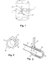
- the air conditioning circuit 1 illustrated in the figure 1 is in known manner a closed circuit or "loop" which comprises, in addition to an internal heat exchanger E, several elements distributed inside the engine compartment of the vehicle, in particular a compressor 2, a cooler or condenser 3 and an evaporator 4, and wherein circulates a refrigerant under pressure, such as R134a or R152, without limitation. All these elements are interconnected by rigid or flexible lines consisting of rigid tubular portions and / or flexible, which have at each of their ends sealed connection means.
- the exchanger E is of coaxial type against the current, and is intended to cool the fluid from the HP line by conduction in contact with the same fluid from the BP line which is heated in exchange.
- this exchanger E consists of a radially inner metal tube 10 which defines in its internal space an internal channel 11 for the fluid coming from the line BP and which is inserted axially inside a radially external tube 20 also of metal delimiting with the tube 20 an outer channel 21 of annular cross section for the fluid from the line HP.
- a spacer insert 30 forming a spacer according to the first example of the invention which is intended to optimize the heat transfer between the HP and LP fluids by the generation of turbulence in the external channel 21, is slidably mounted between the tubes 10 and 20 and in contact therewith, being recessed at an adjustable axial distance from the connecting end 22 of the outer tube 20.
- a stitching 40 such as a filling valve body or a support tube of a pressure sensor, for example by a connecting orifice 23 formed in the outer tube 20.
- the insert 30 is formed by a plurality of ribs 31 circumferentially connected at their respective bases by a cylindrical wall 32 conforming to the wall of the inner tube 10, the total radial height of the wall 32 and each rib 31 being substantially equal to that of the external channel (To the mounting clearance near to allow the sliding of the insert 30).
- a spacing insert 130 according to the second example of the invention is formed by a spiral rib conforming to both the inner tube 10 and the outer tube 20 of the exchanger E by extending helically thereabout (accord to a constant step in this embodiment, it being specified that this step could vary in the axial direction and that the spiral could be discontinuous along the outer channel 21).
- the insert 30, 130 makes it possible at the same time to improve the heat transfer between HP and BP fluids and to serve as a radial spacer between these tubes to ensure their concentricity, in particular in bent or curved sections of exchanger E.
- the inner tube 10 has a protruding portion 12 which protrudes axially from the end 22 of the tube 20 by being integral therewith and which constitutes the connecting pipe of the internal channel 11 of the exchanger E to the line BP of air conditioning circuit 1.
- This end 22 of the tube 20 may be secured to the portion 12 of the tube 10 by a necking which is applied to it by knurling, followed by a circumferential attachment of the end 22 thus narrowed on this portion 12 tube of preferably by welding or soldering (it being specified that other methods such as magnetoforming or even gluing are usable).
- the tube 120 is secured to the tube 110 by crimping with pre-fitting between the respective ends 112 and 122 of the tubes 110 and 120 of an end of a flexible hose 50 for connection to the circuit 1, this hose 50 being in this example mounted in axial abutment against a flange 113 of the tube 110 (schematically the deformations of the respective ends 112 and 122 of the tubes 110 and 120 due to this crimping in contact with the pipe 50).
- the two embodiments of the Figures 6 and 7 have the advantage of allowing the connection of the corresponding end of the exchanger E to the rest of the air conditioning circuit 1 without requiring soldering or brazing of one or more female connector (s), whose massive structure and the preliminary machining required are disadvantages known for this connection because of their weight and the overall assembly overhead they represent for the exchanger E.
Landscapes
- Engineering & Computer Science (AREA)
- Physics & Mathematics (AREA)
- Thermal Sciences (AREA)
- Mechanical Engineering (AREA)
- General Engineering & Computer Science (AREA)
- Geometry (AREA)
- Heat-Exchange Devices With Radiators And Conduit Assemblies (AREA)
- Air-Conditioning For Vehicles (AREA)
Priority Applications (1)
| Application Number | Priority Date | Filing Date | Title |
|---|---|---|---|
| PL10194416T PL2333472T3 (pl) | 2009-12-10 | 2010-12-09 | Wewnętrzny wymiennik ciepła do obwodu klimatyzacji pojazdu samochodowego oraz taki obwód |
Applications Claiming Priority (1)
| Application Number | Priority Date | Filing Date | Title |
|---|---|---|---|
| FR0905970A FR2953917B1 (fr) | 2009-12-10 | 2009-12-10 | Echangeur thermique interne pour circuit de climatisation de vehicule automobile et un tel circuit |
Publications (2)
| Publication Number | Publication Date |
|---|---|
| EP2333472A1 true EP2333472A1 (de) | 2011-06-15 |
| EP2333472B1 EP2333472B1 (de) | 2013-06-05 |
Family
ID=42734096
Family Applications (1)
| Application Number | Title | Priority Date | Filing Date |
|---|---|---|---|
| EP10194416.3A Active EP2333472B1 (de) | 2009-12-10 | 2010-12-09 | Innerer wärmetauscher für einen kraftfahrzeugklimaanlagekreislauf und entsprechender kreislauf |
Country Status (7)
| Country | Link |
|---|---|
| US (1) | US20110139416A1 (de) |
| EP (1) | EP2333472B1 (de) |
| AR (1) | AR079371A1 (de) |
| BR (1) | BRPI1005089B1 (de) |
| ES (1) | ES2426247T3 (de) |
| FR (1) | FR2953917B1 (de) |
| PL (1) | PL2333472T3 (de) |
Cited By (5)
| Publication number | Priority date | Publication date | Assignee | Title |
|---|---|---|---|---|
| FR2996631A1 (fr) * | 2012-10-08 | 2014-04-11 | Commissariat Energie Atomique | Echangeur thermique pour systeme de stockage thermique |
| WO2016022231A1 (en) * | 2014-08-06 | 2016-02-11 | Contitech North America, Inc. | Internal heat exchanger and method for making the same |
| WO2017045933A1 (en) * | 2015-09-18 | 2017-03-23 | Electrolux Appliances Aktiebolag | Air conditioner with a liquid to suction heat exchanger |
| CN107128147A (zh) * | 2016-02-29 | 2017-09-05 | 比亚迪股份有限公司 | 一种同轴管及具有其的空调系统 |
| CN113665316A (zh) * | 2021-08-24 | 2021-11-19 | 浙江吉利控股集团有限公司 | 同轴管、汽车空调系统及车辆 |
Families Citing this family (13)
| Publication number | Priority date | Publication date | Assignee | Title |
|---|---|---|---|---|
| DE102011118761A1 (de) * | 2011-11-17 | 2013-05-23 | GM Global Technology Operations LLC (n. d. Gesetzen des Staates Delaware) | Interner Wärmetauscher für eine Kraftfahrzeug-Klimaanlage |
| JP6172950B2 (ja) * | 2012-02-01 | 2017-08-02 | 株式会社Uacj | 熱交換器用二重管 |
| US9261615B2 (en) | 2012-06-15 | 2016-02-16 | Exxonmobil Upstream Research Company | Seismic anomaly detection using double-windowed statistical analysis |
| WO2014026176A1 (en) * | 2012-08-10 | 2014-02-13 | Contitech Kuehner Gmbh & Cie Kg | Suction flow enhancement for internal heat exchanger |
| DE102014200820A1 (de) * | 2014-01-17 | 2015-07-23 | Siemens Aktiengesellschaft | Verfahren zur Herstellung eines wenigstens eine Wärmeübertragungsfläche aufweisenden Wärmetauschers |
| US20150300745A1 (en) * | 2014-04-16 | 2015-10-22 | Enterex America LLC | Counterflow helical heat exchanger |
| EP3172516B1 (de) * | 2014-07-25 | 2018-05-30 | Hutchinson | Wärmetauscher wie etwa ein interner tauscher für ein fahrzeugklimatisierungssystem sowie system damit |
| WO2018138906A1 (ja) * | 2017-01-30 | 2018-08-02 | 三菱電機株式会社 | 熱交換器及びヒートポンプ給湯器 |
| CN109520354B (zh) * | 2018-12-17 | 2021-11-30 | 青岛钛钽铌锆连续化反应器有限公司 | 一种反应/混合/热交换管及反应器 |
| CN112944960B (zh) * | 2021-03-09 | 2022-05-27 | 格力电器(武汉)有限公司 | 旋流扰动装置及换热管结构 |
| CN113715577B (zh) * | 2021-09-06 | 2023-06-13 | 浙江吉利控股集团有限公司 | 用于非热泵热管理集成模块的集成通道装置及电动车 |
| IT202200025116A1 (it) * | 2022-12-06 | 2024-06-06 | Giacomini Spa | Pannello radiante modulare ad elevata efficienza di scambio termico e metodo di produzione. |
| WO2025137707A1 (en) * | 2023-12-21 | 2025-06-26 | Wain Research Operations Llc | Coaxial gas tube |
Citations (8)
| Publication number | Priority date | Publication date | Assignee | Title |
|---|---|---|---|---|
| CH225906A (de) * | 1938-04-09 | 1943-02-28 | Linde Robert Von | Wärmeaustauscher, insbesondere für Kraftfahrzeugheizungen. |
| FR2484622A1 (fr) * | 1980-05-08 | 1981-12-18 | Wieland Werke Ag | Ensemble de tubes coaxiaux pour la transmission de chaleur entre des liquides ou des gaz |
| JPH05312486A (ja) * | 1992-05-07 | 1993-11-22 | Hitachi Ltd | 金属粒積層熱交換器 |
| US6434972B1 (en) | 1999-09-20 | 2002-08-20 | Behr Gmbh & Co. | Air conditioner with internal heat exchanger and method of making same |
| WO2007013439A1 (ja) | 2005-07-28 | 2007-02-01 | Showa Denko K.K. | 熱交換器 |
| EP1762806A1 (de) | 2005-09-12 | 2007-03-14 | Behr GmbH & Co. KG | Anschlussanordnung, insbesondere für einen Wärmetauscher |
| EP1985945A1 (de) * | 2007-04-27 | 2008-10-29 | Hutchinson | Interner Wärmetauscher für einen Klimaanlagenschaltkreis eines Kraftfahrzeugs, entsprechender Schaltkreis und entsprechendes Anschlussverfahren von zwei Anschlüssen an diesen Wärmetauscher |
| JP2009270802A (ja) * | 2008-04-08 | 2009-11-19 | Tgk Co Ltd | 内部熱交換器 |
Family Cites Families (19)
| Publication number | Priority date | Publication date | Assignee | Title |
|---|---|---|---|---|
| US2120764A (en) * | 1936-09-25 | 1938-06-14 | York Ice Machinery Corp | Refrigeration |
| US2409304A (en) * | 1943-04-01 | 1946-10-15 | Joseph I Morrison | Compressible core for cooling pipes |
| US4045998A (en) * | 1976-03-01 | 1977-09-06 | Phillips Petroleum Company | Temperature control system |
| US4286653A (en) * | 1980-07-21 | 1981-09-01 | Edwards Engineering Corporation | Coaxial tube in tube heat exchanger with inner tube support |
| US5803127A (en) * | 1985-12-16 | 1998-09-08 | R & R Precision Corp. | Coaxial piping systems |
| US4786088A (en) * | 1987-06-25 | 1988-11-22 | Asahi/America, Inc. | Double-containment thermoplastic pipe assembly |
| US5063994A (en) * | 1990-06-26 | 1991-11-12 | Level 1 Technologies, Inc. | Reflux fluid heated patient line |
| US5522453A (en) * | 1995-03-22 | 1996-06-04 | Green; Kenneth E. | Washer fluid heater |
| US6009908A (en) * | 1997-10-30 | 2000-01-04 | Chrysler Corporation | Tube assembly for auxiliary heating and air conditioning system |
| DE60138328D1 (de) * | 2000-02-24 | 2009-05-28 | Calsonic Kansei Corp | Verbindung für Doppelwandröhren, Verfahren zum Hartlöten der Verbindung an Doppelwandröhren, und Klimaanlage für Fahrzeuge |
| DE10053000A1 (de) * | 2000-10-25 | 2002-05-08 | Eaton Fluid Power Gmbh | Klimaanlage mit innerem Wärmetauscher und Wärmetauscherrohr für einen solchen |
| US20040007350A1 (en) * | 2002-07-15 | 2004-01-15 | Lambert Wu | Energy exchanging apparatus |
| US6571832B1 (en) * | 2002-08-08 | 2003-06-03 | Cascade Waterworks Manufacturing Co. | Casing spacer |
| US7753413B2 (en) * | 2003-01-28 | 2010-07-13 | Denso Corporation | Vapour-compression type refrigerating machine and double pipe structure and double pipe joint structure preferably used therefor |
| US7089760B2 (en) * | 2003-05-27 | 2006-08-15 | Calsonic Kansei Corporation | Air-conditioner |
| US20060081362A1 (en) * | 2004-10-19 | 2006-04-20 | Homayoun Sanatgar | Finned tubular heat exchanger |
| DE102005052973B4 (de) * | 2004-11-09 | 2014-11-20 | Denso Corporation | Doppelwandiges Rohr und Herstellungsverfahren dafür |
| DE102006038728B4 (de) * | 2006-08-11 | 2016-06-30 | Halla Visteon Climate Control Corporation | Kältemittelkreislaufsystem |
| JP5081521B2 (ja) * | 2006-08-22 | 2012-11-28 | カルソニックカンセイ株式会社 | 車両用空調装置 |
-
2009
- 2009-12-10 FR FR0905970A patent/FR2953917B1/fr not_active Expired - Fee Related
-
2010
- 2010-12-09 ES ES10194416T patent/ES2426247T3/es active Active
- 2010-12-09 BR BRPI1005089-2A patent/BRPI1005089B1/pt not_active IP Right Cessation
- 2010-12-09 PL PL10194416T patent/PL2333472T3/pl unknown
- 2010-12-09 EP EP10194416.3A patent/EP2333472B1/de active Active
- 2010-12-10 AR ARP100104589A patent/AR079371A1/es active IP Right Grant
- 2010-12-10 US US12/965,199 patent/US20110139416A1/en not_active Abandoned
Patent Citations (8)
| Publication number | Priority date | Publication date | Assignee | Title |
|---|---|---|---|---|
| CH225906A (de) * | 1938-04-09 | 1943-02-28 | Linde Robert Von | Wärmeaustauscher, insbesondere für Kraftfahrzeugheizungen. |
| FR2484622A1 (fr) * | 1980-05-08 | 1981-12-18 | Wieland Werke Ag | Ensemble de tubes coaxiaux pour la transmission de chaleur entre des liquides ou des gaz |
| JPH05312486A (ja) * | 1992-05-07 | 1993-11-22 | Hitachi Ltd | 金属粒積層熱交換器 |
| US6434972B1 (en) | 1999-09-20 | 2002-08-20 | Behr Gmbh & Co. | Air conditioner with internal heat exchanger and method of making same |
| WO2007013439A1 (ja) | 2005-07-28 | 2007-02-01 | Showa Denko K.K. | 熱交換器 |
| EP1762806A1 (de) | 2005-09-12 | 2007-03-14 | Behr GmbH & Co. KG | Anschlussanordnung, insbesondere für einen Wärmetauscher |
| EP1985945A1 (de) * | 2007-04-27 | 2008-10-29 | Hutchinson | Interner Wärmetauscher für einen Klimaanlagenschaltkreis eines Kraftfahrzeugs, entsprechender Schaltkreis und entsprechendes Anschlussverfahren von zwei Anschlüssen an diesen Wärmetauscher |
| JP2009270802A (ja) * | 2008-04-08 | 2009-11-19 | Tgk Co Ltd | 内部熱交換器 |
Cited By (7)
| Publication number | Priority date | Publication date | Assignee | Title |
|---|---|---|---|---|
| FR2996631A1 (fr) * | 2012-10-08 | 2014-04-11 | Commissariat Energie Atomique | Echangeur thermique pour systeme de stockage thermique |
| WO2014056857A1 (fr) * | 2012-10-08 | 2014-04-17 | Commissariat à l'énergie atomique et aux énergies alternatives | Echangeur thermique pour systeme de stockage thermique |
| WO2016022231A1 (en) * | 2014-08-06 | 2016-02-11 | Contitech North America, Inc. | Internal heat exchanger and method for making the same |
| WO2017045933A1 (en) * | 2015-09-18 | 2017-03-23 | Electrolux Appliances Aktiebolag | Air conditioner with a liquid to suction heat exchanger |
| CN107128147A (zh) * | 2016-02-29 | 2017-09-05 | 比亚迪股份有限公司 | 一种同轴管及具有其的空调系统 |
| CN107128147B (zh) * | 2016-02-29 | 2020-05-19 | 比亚迪股份有限公司 | 一种同轴管及具有其的空调系统 |
| CN113665316A (zh) * | 2021-08-24 | 2021-11-19 | 浙江吉利控股集团有限公司 | 同轴管、汽车空调系统及车辆 |
Also Published As
| Publication number | Publication date |
|---|---|
| EP2333472B1 (de) | 2013-06-05 |
| FR2953917B1 (fr) | 2012-01-20 |
| US20110139416A1 (en) | 2011-06-16 |
| BRPI1005089B1 (pt) | 2020-06-23 |
| AR079371A1 (es) | 2012-01-18 |
| ES2426247T3 (es) | 2013-10-22 |
| BRPI1005089A2 (pt) | 2013-04-02 |
| PL2333472T3 (pl) | 2013-10-31 |
| FR2953917A1 (fr) | 2011-06-17 |
Similar Documents
| Publication | Publication Date | Title |
|---|---|---|
| EP2333472B1 (de) | Innerer wärmetauscher für einen kraftfahrzeugklimaanlagekreislauf und entsprechender kreislauf | |
| EP2137477B1 (de) | Wärmetauscher für gas | |
| EP2208955B1 (de) | Wärmeaustauschrippe für ein Wärmeaustauschsystem | |
| EP2273224B1 (de) | Wärmeaustauscheinheit und entsprechender Wärmetauscher sowie Herstellungsverfahren einer Wärmeaustauscheinheit | |
| FR2941522A1 (fr) | Echangeur de chaleur pour deux fluides, en particulier evaporateur de stockage pour dispositif de climatisation | |
| EP2199721B1 (de) | Interner Wärmetauscher für einen Klimaanlagenschaltkreis eines Kraftfahrzeugs, entsprechender Schaltkreis und entsprechendes Anschlussverfahren eines Anschlusses an diesen Wärmetauscher | |
| WO2012000844A1 (fr) | Collecteur pour un echangeur de chaleur et un echangeur de chaleur equipe d'un tel collecteur | |
| EP3172516B1 (de) | Wärmetauscher wie etwa ein interner tauscher für ein fahrzeugklimatisierungssystem sowie system damit | |
| EP3011252A1 (de) | Wärmetauscher, insbesondere für kraftfahrzeugklimaanlagenkreise oder -schaltungen | |
| EP1985945B1 (de) | Interner Wärmetauscher für einen Klimaanlagenschaltkreis eines Kraftfahrzeugs, entsprechender Schaltkreis und entsprechendes Anschlussverfahren von zwei Anschlüssen an diesen Wärmetauscher | |
| FR2914413A1 (fr) | Refroidisseur modulaire en aluminium | |
| EP3198209B1 (de) | Wärmetauscher, insbesondere für kraftfahrzeuge, und verfahren zur herstellung solch eines wärmetauschers | |
| WO2018078300A1 (fr) | Plaque collectrice pour échangeur de chaleur de véhicule automobile | |
| EP3524914A1 (de) | Thermodynamisches heizgerät mit optimiertem mikrokanalkondensator für eine minimale beladung mit kühlflüssigkeit | |
| WO2012131046A1 (fr) | Boîte collectrice pour échangeur thermique notamment pour véhicule automobile, et échangeur thermique correspondant | |
| EP3848660B1 (de) | Dichter anschluss eines verbindungsstücks an einen koaxialen röhrenwärmetauscher | |
| EP3308093B1 (de) | Rippe eines wärmetauschers, insbesondere für ein kraftfahrzeug, und zugehöriger wärmetauscher | |
| FR2875897A1 (fr) | Echangeur de chaleur comportant au moins une bride pour un collecteur de cet echangeur | |
| WO2015007551A1 (fr) | Plaque collectrice de collecteur d'un echangeur de chaleur | |
| WO2011073589A2 (fr) | Procédé de fabrication de tubes pour échangeur de chaleur et échangeur de chaleur comprenant de tels tubes | |
| FR2895059A1 (fr) | Attenuateur de bruit pour flexible hydraulique, flexible qui en est pourvu et systeme de direction assistee l'incorporant | |
| FR3013809A1 (fr) | Bride de chauffe-eau thermodynamique et chauffe-eau thermodynamique | |
| FR2993965A1 (fr) | Echangeur thermique multi-fluides pour vehicules automobiles |
Legal Events
| Date | Code | Title | Description |
|---|---|---|---|
| PUAI | Public reference made under article 153(3) epc to a published international application that has entered the european phase |
Free format text: ORIGINAL CODE: 0009012 |
|
| AK | Designated contracting states |
Kind code of ref document: A1 Designated state(s): AL AT BE BG CH CY CZ DE DK EE ES FI FR GB GR HR HU IE IS IT LI LT LU LV MC MK MT NL NO PL PT RO RS SE SI SK SM TR |
|
| AX | Request for extension of the european patent |
Extension state: BA ME |
|
| 17P | Request for examination filed |
Effective date: 20111024 |
|
| GRAP | Despatch of communication of intention to grant a patent |
Free format text: ORIGINAL CODE: EPIDOSNIGR1 |
|
| RIC1 | Information provided on ipc code assigned before grant |
Ipc: F28F 1/36 20060101ALI20121203BHEP Ipc: F28F 13/12 20060101ALI20121203BHEP Ipc: F28F 1/20 20060101ALI20121203BHEP Ipc: F28D 7/10 20060101AFI20121203BHEP Ipc: F25B 40/00 20060101ALI20121203BHEP |
|
| GRAS | Grant fee paid |
Free format text: ORIGINAL CODE: EPIDOSNIGR3 |
|
| GRAA | (expected) grant |
Free format text: ORIGINAL CODE: 0009210 |
|
| AK | Designated contracting states |
Kind code of ref document: B1 Designated state(s): AL AT BE BG CH CY CZ DE DK EE ES FI FR GB GR HR HU IE IS IT LI LT LU LV MC MK MT NL NO PL PT RO RS SE SI SK SM TR |
|
| REG | Reference to a national code |
Ref country code: GB Ref legal event code: FG4D Free format text: NOT ENGLISH |
|
| REG | Reference to a national code |
Ref country code: CH Ref legal event code: EP |
|
| REG | Reference to a national code |
Ref country code: AT Ref legal event code: REF Ref document number: 615899 Country of ref document: AT Kind code of ref document: T Effective date: 20130615 |
|
| REG | Reference to a national code |
Ref country code: IE Ref legal event code: FG4D Free format text: LANGUAGE OF EP DOCUMENT: FRENCH |
|
| REG | Reference to a national code |
Ref country code: DE Ref legal event code: R096 Ref document number: 602010007542 Country of ref document: DE Effective date: 20130801 |
|
| REG | Reference to a national code |
Ref country code: RO Ref legal event code: EPE |
|
| REG | Reference to a national code |
Ref country code: AT Ref legal event code: MK05 Ref document number: 615899 Country of ref document: AT Kind code of ref document: T Effective date: 20130605 |
|
| REG | Reference to a national code |
Ref country code: ES Ref legal event code: FG2A Ref document number: 2426247 Country of ref document: ES Kind code of ref document: T3 Effective date: 20131022 |
|
| PG25 | Lapsed in a contracting state [announced via postgrant information from national office to epo] |
Ref country code: SI Free format text: LAPSE BECAUSE OF FAILURE TO SUBMIT A TRANSLATION OF THE DESCRIPTION OR TO PAY THE FEE WITHIN THE PRESCRIBED TIME-LIMIT Effective date: 20130605 Ref country code: AT Free format text: LAPSE BECAUSE OF FAILURE TO SUBMIT A TRANSLATION OF THE DESCRIPTION OR TO PAY THE FEE WITHIN THE PRESCRIBED TIME-LIMIT Effective date: 20130605 Ref country code: GR Free format text: LAPSE BECAUSE OF FAILURE TO SUBMIT A TRANSLATION OF THE DESCRIPTION OR TO PAY THE FEE WITHIN THE PRESCRIBED TIME-LIMIT Effective date: 20130906 Ref country code: FI Free format text: LAPSE BECAUSE OF FAILURE TO SUBMIT A TRANSLATION OF THE DESCRIPTION OR TO PAY THE FEE WITHIN THE PRESCRIBED TIME-LIMIT Effective date: 20130605 Ref country code: NO Free format text: LAPSE BECAUSE OF FAILURE TO SUBMIT A TRANSLATION OF THE DESCRIPTION OR TO PAY THE FEE WITHIN THE PRESCRIBED TIME-LIMIT Effective date: 20130905 Ref country code: LT Free format text: LAPSE BECAUSE OF FAILURE TO SUBMIT A TRANSLATION OF THE DESCRIPTION OR TO PAY THE FEE WITHIN THE PRESCRIBED TIME-LIMIT Effective date: 20130605 Ref country code: SE Free format text: LAPSE BECAUSE OF FAILURE TO SUBMIT A TRANSLATION OF THE DESCRIPTION OR TO PAY THE FEE WITHIN THE PRESCRIBED TIME-LIMIT Effective date: 20130605 |
|
| REG | Reference to a national code |
Ref country code: PL Ref legal event code: T3 |
|
| REG | Reference to a national code |
Ref country code: NL Ref legal event code: VDEP Effective date: 20130605 |
|
| REG | Reference to a national code |
Ref country code: LT Ref legal event code: MG4D |
|
| PG25 | Lapsed in a contracting state [announced via postgrant information from national office to epo] |
Ref country code: BG Free format text: LAPSE BECAUSE OF FAILURE TO SUBMIT A TRANSLATION OF THE DESCRIPTION OR TO PAY THE FEE WITHIN THE PRESCRIBED TIME-LIMIT Effective date: 20130905 Ref country code: HR Free format text: LAPSE BECAUSE OF FAILURE TO SUBMIT A TRANSLATION OF THE DESCRIPTION OR TO PAY THE FEE WITHIN THE PRESCRIBED TIME-LIMIT Effective date: 20130605 Ref country code: RS Free format text: LAPSE BECAUSE OF FAILURE TO SUBMIT A TRANSLATION OF THE DESCRIPTION OR TO PAY THE FEE WITHIN THE PRESCRIBED TIME-LIMIT Effective date: 20130605 |
|
| PG25 | Lapsed in a contracting state [announced via postgrant information from national office to epo] |
Ref country code: LV Free format text: LAPSE BECAUSE OF FAILURE TO SUBMIT A TRANSLATION OF THE DESCRIPTION OR TO PAY THE FEE WITHIN THE PRESCRIBED TIME-LIMIT Effective date: 20130605 |
|
| PG25 | Lapsed in a contracting state [announced via postgrant information from national office to epo] |
Ref country code: CZ Free format text: LAPSE BECAUSE OF FAILURE TO SUBMIT A TRANSLATION OF THE DESCRIPTION OR TO PAY THE FEE WITHIN THE PRESCRIBED TIME-LIMIT Effective date: 20130605 Ref country code: EE Free format text: LAPSE BECAUSE OF FAILURE TO SUBMIT A TRANSLATION OF THE DESCRIPTION OR TO PAY THE FEE WITHIN THE PRESCRIBED TIME-LIMIT Effective date: 20130605 Ref country code: IS Free format text: LAPSE BECAUSE OF FAILURE TO SUBMIT A TRANSLATION OF THE DESCRIPTION OR TO PAY THE FEE WITHIN THE PRESCRIBED TIME-LIMIT Effective date: 20131005 Ref country code: SK Free format text: LAPSE BECAUSE OF FAILURE TO SUBMIT A TRANSLATION OF THE DESCRIPTION OR TO PAY THE FEE WITHIN THE PRESCRIBED TIME-LIMIT Effective date: 20130605 Ref country code: PT Free format text: LAPSE BECAUSE OF FAILURE TO SUBMIT A TRANSLATION OF THE DESCRIPTION OR TO PAY THE FEE WITHIN THE PRESCRIBED TIME-LIMIT Effective date: 20131007 |
|
| PG25 | Lapsed in a contracting state [announced via postgrant information from national office to epo] |
Ref country code: NL Free format text: LAPSE BECAUSE OF FAILURE TO SUBMIT A TRANSLATION OF THE DESCRIPTION OR TO PAY THE FEE WITHIN THE PRESCRIBED TIME-LIMIT Effective date: 20130605 |
|
| PLBE | No opposition filed within time limit |
Free format text: ORIGINAL CODE: 0009261 |
|
| STAA | Information on the status of an ep patent application or granted ep patent |
Free format text: STATUS: NO OPPOSITION FILED WITHIN TIME LIMIT |
|
| PG25 | Lapsed in a contracting state [announced via postgrant information from national office to epo] |
Ref country code: DK Free format text: LAPSE BECAUSE OF FAILURE TO SUBMIT A TRANSLATION OF THE DESCRIPTION OR TO PAY THE FEE WITHIN THE PRESCRIBED TIME-LIMIT Effective date: 20130605 |
|
| 26N | No opposition filed |
Effective date: 20140306 |
|
| REG | Reference to a national code |
Ref country code: DE Ref legal event code: R097 Ref document number: 602010007542 Country of ref document: DE Effective date: 20140306 |
|
| BERE | Be: lapsed |
Owner name: HUTCHINSON Effective date: 20131231 |
|
| PG25 | Lapsed in a contracting state [announced via postgrant information from national office to epo] |
Ref country code: MC Free format text: LAPSE BECAUSE OF FAILURE TO SUBMIT A TRANSLATION OF THE DESCRIPTION OR TO PAY THE FEE WITHIN THE PRESCRIBED TIME-LIMIT Effective date: 20130605 |
|
| PG25 | Lapsed in a contracting state [announced via postgrant information from national office to epo] |
Ref country code: LU Free format text: LAPSE BECAUSE OF FAILURE TO SUBMIT A TRANSLATION OF THE DESCRIPTION OR TO PAY THE FEE WITHIN THE PRESCRIBED TIME-LIMIT Effective date: 20131209 |
|
| REG | Reference to a national code |
Ref country code: IE Ref legal event code: MM4A |
|
| PG25 | Lapsed in a contracting state [announced via postgrant information from national office to epo] |
Ref country code: IE Free format text: LAPSE BECAUSE OF NON-PAYMENT OF DUE FEES Effective date: 20131209 Ref country code: BE Free format text: LAPSE BECAUSE OF NON-PAYMENT OF DUE FEES Effective date: 20131231 |
|
| PG25 | Lapsed in a contracting state [announced via postgrant information from national office to epo] |
Ref country code: SM Free format text: LAPSE BECAUSE OF FAILURE TO SUBMIT A TRANSLATION OF THE DESCRIPTION OR TO PAY THE FEE WITHIN THE PRESCRIBED TIME-LIMIT Effective date: 20130605 |
|
| PG25 | Lapsed in a contracting state [announced via postgrant information from national office to epo] |
Ref country code: CY Free format text: LAPSE BECAUSE OF FAILURE TO SUBMIT A TRANSLATION OF THE DESCRIPTION OR TO PAY THE FEE WITHIN THE PRESCRIBED TIME-LIMIT Effective date: 20130605 Ref country code: TR Free format text: LAPSE BECAUSE OF FAILURE TO SUBMIT A TRANSLATION OF THE DESCRIPTION OR TO PAY THE FEE WITHIN THE PRESCRIBED TIME-LIMIT Effective date: 20130605 |
|
| PG25 | Lapsed in a contracting state [announced via postgrant information from national office to epo] |
Ref country code: MK Free format text: LAPSE BECAUSE OF FAILURE TO SUBMIT A TRANSLATION OF THE DESCRIPTION OR TO PAY THE FEE WITHIN THE PRESCRIBED TIME-LIMIT Effective date: 20130605 Ref country code: HU Free format text: LAPSE BECAUSE OF FAILURE TO SUBMIT A TRANSLATION OF THE DESCRIPTION OR TO PAY THE FEE WITHIN THE PRESCRIBED TIME-LIMIT; INVALID AB INITIO Effective date: 20101209 |
|
| REG | Reference to a national code |
Ref country code: CH Ref legal event code: PL |
|
| GBPC | Gb: european patent ceased through non-payment of renewal fee |
Effective date: 20141209 |
|
| PG25 | Lapsed in a contracting state [announced via postgrant information from national office to epo] |
Ref country code: MT Free format text: LAPSE BECAUSE OF FAILURE TO SUBMIT A TRANSLATION OF THE DESCRIPTION OR TO PAY THE FEE WITHIN THE PRESCRIBED TIME-LIMIT Effective date: 20130605 |
|
| PG25 | Lapsed in a contracting state [announced via postgrant information from national office to epo] |
Ref country code: LI Free format text: LAPSE BECAUSE OF NON-PAYMENT OF DUE FEES Effective date: 20141231 Ref country code: GB Free format text: LAPSE BECAUSE OF NON-PAYMENT OF DUE FEES Effective date: 20141209 Ref country code: CH Free format text: LAPSE BECAUSE OF NON-PAYMENT OF DUE FEES Effective date: 20141231 |
|
| REG | Reference to a national code |
Ref country code: FR Ref legal event code: PLFP Year of fee payment: 6 |
|
| REG | Reference to a national code |
Ref country code: FR Ref legal event code: PLFP Year of fee payment: 7 |
|
| REG | Reference to a national code |
Ref country code: FR Ref legal event code: PLFP Year of fee payment: 8 |
|
| PG25 | Lapsed in a contracting state [announced via postgrant information from national office to epo] |
Ref country code: AL Free format text: LAPSE BECAUSE OF FAILURE TO SUBMIT A TRANSLATION OF THE DESCRIPTION OR TO PAY THE FEE WITHIN THE PRESCRIBED TIME-LIMIT Effective date: 20130605 |
|
| PGFP | Annual fee paid to national office [announced via postgrant information from national office to epo] |
Ref country code: RO Payment date: 20201126 Year of fee payment: 11 |
|
| PGFP | Annual fee paid to national office [announced via postgrant information from national office to epo] |
Ref country code: ES Payment date: 20210223 Year of fee payment: 11 |
|
| PG25 | Lapsed in a contracting state [announced via postgrant information from national office to epo] |
Ref country code: RO Free format text: LAPSE BECAUSE OF NON-PAYMENT OF DUE FEES Effective date: 20211209 |
|
| REG | Reference to a national code |
Ref country code: ES Ref legal event code: FD2A Effective date: 20230224 |
|
| PGFP | Annual fee paid to national office [announced via postgrant information from national office to epo] |
Ref country code: PL Payment date: 20221208 Year of fee payment: 13 |
|
| PG25 | Lapsed in a contracting state [announced via postgrant information from national office to epo] |
Ref country code: ES Free format text: LAPSE BECAUSE OF NON-PAYMENT OF DUE FEES Effective date: 20211210 |
|
| P01 | Opt-out of the competence of the unified patent court (upc) registered |
Effective date: 20230526 |
|
| PG25 | Lapsed in a contracting state [announced via postgrant information from national office to epo] |
Ref country code: PL Free format text: LAPSE BECAUSE OF NON-PAYMENT OF DUE FEES Effective date: 20231209 |
|
| PGFP | Annual fee paid to national office [announced via postgrant information from national office to epo] |
Ref country code: DE Payment date: 20251211 Year of fee payment: 16 |
|
| PGFP | Annual fee paid to national office [announced via postgrant information from national office to epo] |
Ref country code: IT Payment date: 20251223 Year of fee payment: 16 |
|
| PGFP | Annual fee paid to national office [announced via postgrant information from national office to epo] |
Ref country code: FR Payment date: 20251222 Year of fee payment: 16 |