EP2339100B9 - Agencement d'engrenage d'une ferrure de bielle, ferrure de bielle dotée d'un tel agencement d'engrenage ainsi que fenêtre, porte ou analogue dotés d'une telle ferrure de bielle - Google Patents
Agencement d'engrenage d'une ferrure de bielle, ferrure de bielle dotée d'un tel agencement d'engrenage ainsi que fenêtre, porte ou analogue dotés d'une telle ferrure de bielle Download PDFInfo
- Publication number
- EP2339100B9 EP2339100B9 EP09015923.7A EP09015923A EP2339100B9 EP 2339100 B9 EP2339100 B9 EP 2339100B9 EP 09015923 A EP09015923 A EP 09015923A EP 2339100 B9 EP2339100 B9 EP 2339100B9
- Authority
- EP
- European Patent Office
- Prior art keywords
- gear
- toothings
- individual
- toothing
- rotation
- Prior art date
- Legal status (The legal status is an assumption and is not a legal conclusion. Google has not performed a legal analysis and makes no representation as to the accuracy of the status listed.)
- Active
Links
Images




Classifications
-
- E—FIXED CONSTRUCTIONS
- E05—LOCKS; KEYS; WINDOW OR DOOR FITTINGS; SAFES
- E05C—BOLTS OR FASTENING DEVICES FOR WINGS, SPECIALLY FOR DOORS OR WINDOWS
- E05C9/00—Arrangements of simultaneously actuated bolts or other securing devices at well-separated positions on the same wing
- E05C9/04—Arrangements of simultaneously actuated bolts or other securing devices at well-separated positions on the same wing with two sliding bars moved in opposite directions when fastening or unfastening
- E05C9/041—Arrangements of simultaneously actuated bolts or other securing devices at well-separated positions on the same wing with two sliding bars moved in opposite directions when fastening or unfastening with rack and pinion mechanism
Definitions
- the invention further relates to a drive rod fitting with a gear assembly of the above type and a window, a door or the like with such an espagnolette fitting.
- the single toothing with a larger diameter engages in a rack on a drive slide, which in turn can be coupled with a first drive rod.
- the input-side toothing element meshes with a further toothing element provided on the output side of the toothed transmission.
- the toothing of the output-side toothing element has a uniform tip diameter.
- the output-side toothed element engages in a Rack on a second drive slide, to which a second drive rod can be connected.
- the input-side toothed element If the input-side toothed element is rotated by means of the handle, it drives the first drive slide with its rectilinear motion via its individual toothing with a larger diameter and the output-side toothed element with a rotational movement via its individual toothing with a smaller diameter.
- the rotating output-side toothed element in turn moves the second drive slide translationally in a direction opposite to the direction of movement of the first drive slide.
- the drive rods connected thereto are moved into two different switching positions, namely into a locking position and into an open position. Since only two different positions are to be approached, the stroke to be executed by the drive rods is dimensioned relatively small.
- the inventive concept allows to accommodate a gear assembly regardless of largemaschinegenhübe in a small, to be produced on the relevant window or door gear rack.
- a small gear recording of the window or door wing is at most slightly weakened.
- a double-toothed gear element with flat individual gears combined with a further double-toothed gear element but the individual gears are offset in the direction of the axis of rotation of the respective gear element against each other. Due to the offset of the individual gears in the direction of the axis of rotation, the dimension of the transmission element in the transverse direction of the axis of rotation is minimized. In conjunction with the transmission element with evenly spaced individual gears results in a gear assembly to which precautions both to minimize the dimension of the construction in the direction of the axes of rotation of the transmission elements as well as to minimize the dimension of the building are made transversely thereto. A compact design of the gear assembly as a whole with simultaneous feasibility of largemaschinegenhübe is the result.
- the drivetrain-side counter toothings are the front teeth provided on the transmission elements in the direction of the axes of rotation of the transmission element arranged one above the other by being provided on drive slides of the drive rod fitting, which in turn lie one above the other in the direction of the axes of rotation of the transmission elements.
- the drive slide of the espagnolette fitting are driven in opposite directions by means of the gear elements and overlap each other in the drive direction. In their opposite movement, the drive slide in the drive direction are movably guided together (claim 3). Additional guide devices for the drive slide are required only to a small extent or completely dispensable. According to the invention, an additional guidance of each drive slide on a transmission housing of the transmission arrangement is preferred.
- the drive slide according to claim 4 in the region of their mutual overlap on a reduced width.
- the characterizing features of claim 5 are provided according to the invention. Accordingly, the gear element with plane-like individual teeth on that side on which it is covered by the transmission element with offset individual teeth, a bearing point. Between the bearing point and the transmission element with the same level individual teeth a free space is provided, which is arranged in the axial extension of the bearing.
- the transmission element with offset individual gears when rotating around its axis of rotation move it with the larger diameter single toothing. Due to its arrangement in the axial extension of the bearing point of the covered gear element with level individual gears allows the free space a relatively large mutual overlap of the two gear elements with simultaneous storage of the covered gear element on the cover side. This possibility is of particular importance for the gear arrangement according to the invention, since the overlapping gear element for realizing large driving rod strokes has a relatively large diameter. Regardless of the possibility of largemaschinebe the transmission elements can be accommodated in particular in gear housings in which passages for mounting screws of a handle rosette a relatively small normalized distance (for example, 43mm) have. Due to the mutual overlap provided in the case of the invention, an overall dimension in the radial direction of the axes of rotation results for the gear elements, which permits installation of the gear elements between the passages for fastening the handle rosette.
- the overlaid gear element with flat individual gears not only on the cover side but also on the opposite side of a bearing point. Due to the two-sided bearings results for the covered gear element is a particularly effective and therefore load-bearing storage even with extensive coverage by the transmission element with offset individual gears.
- the overlapping transmission element with staggered individual gears can consequently also absorb large loads.
- in combination with a transmission element mounted on both sides with plane-identical individual teeth results in a particularly load-bearing overall arrangement.
- the transmission element is provided with level individual gears according to the invention with a bearing projection, which forms the space for the overlapping transmission element with offset individual teeth by a return to the bearing point of the covered transmission element (claim 8).
- an embodiment of the invention is characterized in the case of which the covered gear element with integral equal teeth and the associated bearing projection are integrally formed.
- the relevant transmission element and its bearing projection preferably consist of one and the same material (claim 10). It has proven particularly expedient to produce gear element and bearing projection as a uniform casting.
- the bearing points of the gear or the transmission elements are directly part of the rotary bearings of the transmission elements (claim 11).
- the bearing point (s) of the or the transmission elements as concentric with the respective axis of rotation journal bearing with circular cross section (claim 12).
- the inventive concept is implemented in a case in which the gear assembly has a gear housing with mounting options for a particular manual actuator.
- FIGS. 1 and 2 is a gear assembly 1 part of a drive rod fitting 2, which at an in FIG. 1 merely indicated Wing 3 of a window 4 is mounted.
- Driving rods 5, 6 of the espagnolette 2 are connected in a conventional manner via internally toothed coupling shoes 7, 8 to drive slide 9, 10 of the gear assembly 1.
- the drive rods 5, 6 are only in FIG. 1 shown.
- the drive slide 9, 10 are longitudinally movably guided on a transmission housing 11, which in turn is composed of housing shells 12a, 12b. In their longitudinal direction, the drive slide 9, 10 overlap each other. In the overlapping area they have a reduced width.
- the drive slides 9, 10 are provided with lateral projections which engage in guide grooves of the housing shells 12a, 12b ( FIG. 3 ).
- the drive slide 9, 10 in their longitudinal direction mutually.
- the housing shells 12a, 12b are riveted together as usual.
- a through hole 15 and a threaded sleeve 16 are provided.
- the through-holes 15 and the threaded sleeves 16 serve as passages for fastening means, in the example shown for fastening screws, which serve for fixing a handle rosette on the interior surface of the wing 3.
- About the handle rosette is one in the FIGS. 7 to 9 indicated actuating device, in this case a manual operating handle, rotatably supported on the wing 3.
- the threaded sleeves 16 on the housing shells 12a, 12b are each aligned with a passage bore 15 on the opposite housing shell 12a, 12b.
- the fastening screws are screwed from the room inside through the handle rosette into the threaded sleeves 16.
- the center distance of the threaded sleeves 16 in the longitudinal direction of the drive slide 9, 10 or in the longitudinal direction of the drive rods 5, 6 is dimensioned as usual and is 43mm in the example shown.
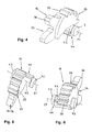
- a gear 17 designed as a gear transmission is accommodated in the interior of the gear housing 11.
- the transmission 17 comprises an input-side transmission element 18 and an output-side transmission element 19. Both transmission elements 18, 19 are designed as toothed elements and manufactured as castings.
- the input-side transmission element 18 is mounted on the transmission housing 11 so as to be rotatable about an axis of rotation 20, the output-side transmission element 19 is rotatable about an axis of rotation 21.
- the axle journals 22a, 22b engage in corresponding bearing eyes 23a, 23b on the housing shells 12a, 12b of the gear housing 11.
- a square socket 24 of the input-side gear member 18 is used in a conventional manner for receiving a correspondingly shaped handle mandrel of the manual operating handle for the espagnolette 2.
- the input-side gear element 18 has a front toothing 25.
- This is as a double toothing formed as such and comprises two individual teeth 26, 27.
- the individual gears 26, 27 are offset from each other.
- the tip circle of the individual toothing 26 has a larger diameter than the tip circle of the individual toothing 27. Teeth 28 of the individual toothing 26 are therefore higher than teeth 29 of the individual toothing 27.
- the spur toothing 32 on the output-side gear element 19 is formed as a double toothing.
- the face toothing 32 of the output-side gear element 19 comprises a single toothing 34 with a larger tip diameter. Teeth 35 of the individual teeth 33 have a lower height than the teeth 36 of the individual teeth 34.
- the spur toothing 32 of the output-side gear element 19 engages in a drive rod-side counter toothing in the form of a toothed rack 37 with teeth 38 ( FIG. 2 ).
- the individual gears 33, 34 of the output-side gear element 19 are not in the axial direction of the relevant transmission element offset from each other but rather level, ie arranged in a common, perpendicular to the axis of rotation 21 of the output-side gear member 19 aligned plane.
- the output-side gear element 19 consequently has a small overall height in the direction of its axis of rotation 21 despite double toothing. All individual gears 26, 27, 33, 34 extend only over part of the circumference of the respective transmission element 18, 19.
- the input-side gear element 18 is offset from the output-side gear element 19 in the direction of the axes of rotation 20, 21 such that it comes to lie with the one large head circle diameter having individual teeth 26 adjacent the output-side gear element 19 and at the one small tip diameter having individual teeth 27 with the individual teeth 33 of the output-side gear member 19 meshes.
- the manual actuation handle inserted with its gripping mandrel into the inner square 24 of the input-side gear element 18 is to be rotated in the desired direction of rotation.
- the rotational movement of the manual operating handle is by the input side gear member 18 directly in a longitudinal movement of the drive slide 10 and drive rod 6 and via the drive-connected to the input side gear element 18 output-side transmission element 19 in an opposite longitudinal movement of the drive slide. 9 and drive rod 5 implemented.
- Such longitudinal movements of the drive slide 9, 10 and the drive rods 5, 6 are used to transfer the drive rod fitting 2 in three different switching states, namely in a locked state ( FIG. 7 ), a rotational opening state ( FIG. 8 ) and a night ventilation state ( FIG. 9 ).
- Is the espagnolette fitting 2 in the locked state according to FIG. 7 project rod exclusions, which are connected via the drive rods 5, 6 to the drive slide 9, 10, in the longitudinal direction of the drive rods 5, 6 in closing pieces, which in turn are provided on a wing 3 of the window 4 associated fixed frame.
- a mounted on the drive slides 9, 10 locking pin 39 in a fixed frame-side locking piece 40 according to FIG. 10 retracted and there in an in FIG. 10 arranged with I designated area.
- the wing 3 is accordingly locked to the associated fixed frame against opening.
- the drive rods 5, 6 and the drive slide 9, 10 must perform a long stroke in the transfer of the drive rod fitting 2 in the different switching states.
- the in the FIGS. 7 to 9 indicated hand-operated handle is in the illustrated example case for transfer from its the locking state of the espagnolette 2 associated position ( FIG. 7 ) in the position of the night ventilation state ( FIG. 9 ) over an angle of 135 °.
- the stroke of the drive rods 5, 6 between their locking position and their rotational opening position is present 18mm and between the rotational opening position and the gap ventilation position another 9mm.
- the long stroke of the espagnolette fitting 2 is made possible by the large diameters of the individual toothings 26, 34 provided on the input-side gear element 28 and the output-side gear element 19.
- the individual toothing 26 comes with three teeth 28 and the individual toothing 34 with two teeth 36. Also, this small number of teeth contributes to the compact design of the transmission 17.
- the total extension of the composite of the input-side gear member 18 and the output-side gear member 19 transmission 17 in the longitudinal direction of the drive slide 9, 10 and the drive rods 5, 6 be as large as the axial distance of the threaded sleeves 16 Otherwise, the transmission 17 could not be accommodated inside the transmission housing 11.
- the required small dimension of the construction of the gear 17 is achieved in that the axes of rotation 20, 21 of the input-side gear member 18 and the output-side gear member 19 in the longitudinal direction of the drive slide 9, 10 and the drive rods 5, 6 are moved close together. Due to the small radial distance of their axes of rotation 20, 21, the input-side gear element 18 and the output-side gear element 19 in the radial direction of the axes of rotation 20, 21 a relatively large mutual overlap. The overlapping input-side gear member 18 projects at a corresponding rotational position with the individual toothing 26 far beyond the covered output-side gear element 19 (FIG. FIG. 1 ).
- a free space 43 is provided on the overlapping input-side gear element 18 associated cover side of the output-side gear element 19 between this and a designed as a circular cylindrical journal 42 bearing point of the output-side gear element 19. This extends in the axial extension of the axle journal 42.
- the overlapping input-side gear member 18 moves with rotation about its axis of rotation 20 with the individual teeth 26.
- the clearance 43 is formed by the fact that an integrally formed on the output side gear member 19 bearing projection 44 relative to the axle journal 42 in the radial direction of the rotation axis 21 springs back.
- axle journal 42 engages in a corresponding bearing eye on the gear housing 11. This bearing eye is in FIG. 2 obscured by the output side gear member 19.
- the gear 17 Due to the two-sided storage of both the input-side gear element 18 and the output-side gear element 19, the gear 17 is able to take large and acting in the transverse direction of the axes of rotation 20, 21 loads and remove it into the gear housing 11. Regardless, the gear 17 and with this the entire gear assembly 1 has a very compact design.
Landscapes
- Engineering & Computer Science (AREA)
- Mechanical Engineering (AREA)
- Gear Transmission (AREA)
Claims (15)
- Ensemble de transmission d'une ferrure de crémone (2) pour des fenêtres (4), des portes ou analogues, avec une transmission (17) qui comprend deux éléments de transmission (18, 19), qui sont rotatifs autour d'axes de rotation (20, 21) parallèles et mutuellement décalés en direction radiale et qui présentent chacun une denture droite (25, 32) au niveau de laquelle les éléments de transmission (18, 19) engrènent entre eux et par laquelle les éléments de transmission (18, 19) s'engagent respectivement dans une denture complémentaire (30, 37) côté tige de crémone,- sachant que chacune des dentures complémentaires (30, 37) côté tige de crémone est associée à une tige de crémone (5, 6) de la ferrure de crémone (2) et que les tiges de crémone (5, 6) peuvent être entraînées en sens contraires au moyen des éléments de transmission (18, 19) s'engageant dans les dentures complémentaires (30, 37) côté tige de crémone,- sachant que la denture droite (32) d'un des éléments de transmission (18, 19) est réalisée sous forme de denture double avec des dentures simples (33, 34) qui présentent des diamètres de cercle de tête différents,- et sachant que la denture droite (32) réalisée sous forme de denture double engrène au niveau de la denture simple (33) de plus petit diamètre avec la denture droite (25) de l'autre élément de transmission (18) et s'engage par la denture simple (34) de plus grand diamètre dans la denture complémentaire associée (37) côté tige de crémone,caractérisé en ce que la denture double présente des dentures simples coplanaires (33, 34), sachant que la denture simple (33) de plus petit diamètre et la denture simple (34) de plus grand diamètre se succèdent, dans un plan de section commun de l'élément de transmission concerné (19), dans la direction circonférentielle de ce dernier, et que le plan de section s'étend perpendiculairement à l'axe de rotation (21) de l'élément de transmission concerné (19).
- Ensemble de transmission selon la revendication 1, caractérisé en ce que les dentures droites (25, 32) des deux éléments de transmission (18, 19) sont réalisées sous forme de dentures doubles, sachant qu'en plus de l'élément de transmission (19) à dentures simples coplanaires (33, 34), il est prévu un élément de transmission (18) à dentures simples décalées (26, 27), dont la denture simple (27) de plus petit diamètre et la denture simple (26) de plus grand diamètre sont mutuellement décalées dans la direction de l'axe de rotation (20) de l'élément de transmission concerné (18), et dont la denture simple (26) de plus grand diamètre, lors de la rotation autour de l'axe de rotation (20), recouvre l'élément de transmission (19) à dentures simples coplanaires (33, 34) dans la direction radiale des axes de rotation (20, 21).
- Ensemble de transmission selon l'une des revendications précédentes, avec deux éléments de transmission (18, 19) à denture double, sachant que l'un (19) des éléments de transmission présente des dentures simples coplanaires (33, 34) et l'autre élément de transmission (18) des dentures simples décalées (26, 27), caractérisé en ce que les dentures (30, 37), complémentaires côté tige de crémone des dentures droites (25, 32) prévues sur les éléments de transmission (18, 19), sont disposées l'une au-dessus de l'autre dans la direction des axes de rotation (20, 21) des éléments de transmission (18, 19), par le fait que les dentures complémentaires (30, 37) côté tige de crémone sont prévues sur des coulisseaux d'entraînement (9, 10) de la ferrure de crémone (2) superposés dans la direction des axes de rotation (20, 21) des éléments de transmission (18, 19), sachant que les coulisseaux d'entraînement (9, 10) peuvent être entrainés en sens contraires au moyen des dentures simples (26, 34) de plus grand diamètre s'engageant dans les dentures complémentaires (30, 37) côté tige de crémone et se chevauchent mutuellement dans la direction d'entraînement, et sachant que les coulisseaux d'entraînement (9, 10), lors de leur mouvement en sens contraires, sont guidés en déplacement l'un contre l'autre dans la direction d'entraînement.
- Ensemble de transmission selon l'une des revendications précédentes, caractérisé en ce que les coulisseaux d'entraînement (9, 10) de la ferrure de crémone (2) présentent une largeur réduite dans la région de leur chevauchement mutuel.
- Ensemble de transmission selon l'une des revendications précédentes, caractérisé en ce que l'élément de transmission (19) à dentures simples coplanaires (33, 34) présente un palier (42) sur le côté de recouvrement, et en ce qu'un espace libre (43) est prévu sur le côté de recouvrement de l'élément de transmission (19) à dentures simples coplanaires (33, 34), entre cet élément de transmission (19) et son palier (42), espace qui est disposé dans le prolongement axial du palier (42) et dans lequel l'élément de transmission (18) à dentures simples décalées (26, 27) se meut par la denture simple (26) de plus grand diamètre lors de la rotation autour de son axe de rotation (20).
- Ensemble de transmission selon l'une des revendications précédentes, caractérisé en ce que l'élément de transmission recouvert (19) à dentures simples coplanaires (33, 34) présente un autre palier (45) sur le côté opposé au côté de recouvrement dans la direction des axes de rotation (20, 21).
- Ensemble de transmission selon l'une des revendications précédentes, caractérisé en ce que l'élément de transmission recouvrant (18) à dentures simples décalées (26, 27) présente un palier respectif (22a, 22b) de part et d'autre le long de son axe de rotation (20).
- Ensemble de transmission selon l'une des revendications précédentes, caractérisé en ce que le palier (42) de l'élément de transmission recouvert (19) à dentures simples coplanaires (33, 34) est prévu sur une saillie de palier (44) qui est reliée à l'élément de transmission recouvert (19) à dentures simples coplanaires (33, 34) et qui dépasse sur le côté de recouvrement de ce dernier dans la direction des axes de rotation (20, 21), et en ce que la saillie de palier (44), présente entre le palier (42) et l'élément de transmission recouvert (19) à dentures simples coplanaires (33, 34), est en retrait par rapport au palier (42) dans la direction radiale des axes de rotation (20, 21), en formant l'espace libre (43) pour l'élément de transmission recouvrant (18) à dentures simples décalées (26, 27).
- Ensemble de transmission selon l'une des revendications précédentes, caractérisé en ce que la saillie de palier (44), présente entre l'élément de transmission recouvert (19) à dentures simples coplanaires (33, 34) et son palier (42), est élargie par rapport au palier (42) en dehors de l'espace libre (43).
- Ensemble de transmission selon l'une des revendications précédentes, caractérisé en ce que l'élément de transmission recouvert (19) à dentures simples coplanaires (33, 34) et la saillie de palier (44) qui lui est reliée sont réalisés d'un seul tenant et de préférence dans le même matériau.
- Ensemble de transmission selon l'une des revendications précédentes, caractérisé en ce que l'élément de transmission recouvert (19) à dentures simples coplanaires (33, 34) et/ou l'élément de transmission recouvrant (18) à dentures simples décalées (26, 27) est/sont monté(s) à rotation autour de son/leurs axe(s) de rotation (20, 21) au niveau du/des palier(s) (22a, 22b, 42, 45).
- Ensemble de transmission selon l'une des revendications précédentes, caractérisé en ce que le/les palier(s) (22a, 22b, 42, 45) de l'élément de transmission recouvert (19) à dentures simples coplanaires (33, 34) et/ou de l'élément de transmission recouvrant (18) à dentures simples décalées (26, 27) est/sont réalisés sous forme de tourillon(s) de section circulaire, concentrique(s) à l'axe/aux axes de rotation (20, 21) dudit/desdits élément(s) de transmission.
- Ensemble de transmission selon l'une des revendications précédentes, avec un boîtier de transmission (11) dans lequel sont reçus les éléments de transmission (18, 19) et qui présente des passages (15, 16), pouvant être traversés dans la direction des axes de rotation (20, 21) des éléments de transmission (18, 19) et destinés à des moyens de fixation permettant de fixer un dispositif d'actionnement sur le boîtier de transmission (11), caractérisé en ce que les éléments de transmission (18, 19) sont disposés entre les passages (15, 16) pour les moyens de fixation.
- Ferrure de crémone avec un ensemble de transmission (1) selon l'une des revendications 1 à 13.
- Fenêtre, porte ou analogue avec une ferrure de crémone (2) selon la revendication 14.
Priority Applications (3)
| Application Number | Priority Date | Filing Date | Title |
|---|---|---|---|
| DK09015923.7T DK2339100T3 (da) | 2009-12-23 | 2009-12-23 | Gearsamling på et drivstangbeslag, drivstangbeslag med en sådan gearsamling samt vindue, dør eller deslignende med et sådant drivstangbeslag |
| PL09015923T PL2339100T3 (pl) | 2009-12-23 | 2009-12-23 | Układ przekładni okucia z drążkami napędowymi, okucie z drążkami napędowymi z tego rodzaju układem przekładni, a także okno, drzwi lub tym podobne z tego rodzaju okuciem z drążkami napędowymi |
| EP09015923.7A EP2339100B9 (fr) | 2009-12-23 | 2009-12-23 | Agencement d'engrenage d'une ferrure de bielle, ferrure de bielle dotée d'un tel agencement d'engrenage ainsi que fenêtre, porte ou analogue dotés d'une telle ferrure de bielle |
Applications Claiming Priority (1)
| Application Number | Priority Date | Filing Date | Title |
|---|---|---|---|
| EP09015923.7A EP2339100B9 (fr) | 2009-12-23 | 2009-12-23 | Agencement d'engrenage d'une ferrure de bielle, ferrure de bielle dotée d'un tel agencement d'engrenage ainsi que fenêtre, porte ou analogue dotés d'une telle ferrure de bielle |
Publications (3)
| Publication Number | Publication Date |
|---|---|
| EP2339100A1 EP2339100A1 (fr) | 2011-06-29 |
| EP2339100B1 EP2339100B1 (fr) | 2013-02-13 |
| EP2339100B9 true EP2339100B9 (fr) | 2013-07-03 |
Family
ID=42227744
Family Applications (1)
| Application Number | Title | Priority Date | Filing Date |
|---|---|---|---|
| EP09015923.7A Active EP2339100B9 (fr) | 2009-12-23 | 2009-12-23 | Agencement d'engrenage d'une ferrure de bielle, ferrure de bielle dotée d'un tel agencement d'engrenage ainsi que fenêtre, porte ou analogue dotés d'une telle ferrure de bielle |
Country Status (3)
| Country | Link |
|---|---|
| EP (1) | EP2339100B9 (fr) |
| DK (1) | DK2339100T3 (fr) |
| PL (1) | PL2339100T3 (fr) |
Families Citing this family (2)
| Publication number | Priority date | Publication date | Assignee | Title |
|---|---|---|---|---|
| EP2581531B1 (fr) * | 2011-10-14 | 2015-01-21 | Roto Frank AG | Engrenage pour une espagnolette de fenêtre, de porte ou analogue |
| US11668119B2 (en) * | 2019-04-23 | 2023-06-06 | Volvo Car Corporation | Coupler-actuator assembly for a powered latch system |
Family Cites Families (4)
| Publication number | Priority date | Publication date | Assignee | Title |
|---|---|---|---|---|
| GB2300665B (en) | 1995-05-06 | 1998-05-20 | Plus Plan | Operating mechanism for espagnolette fastening system |
| GB9607908D0 (en) * | 1996-04-17 | 1996-06-19 | Raytec Pressworks Plastics Ltd | Shoot bolt mechanism |
| GB2360062B (en) * | 2000-03-10 | 2002-05-22 | Santos Manuf Lda | Improvements in espagnolette bolting systems |
| ATE353391T1 (de) * | 2002-06-05 | 2007-02-15 | Master Srl | Bewegungsvorrichtung, insbesondere für anwendung mit fenstergriffen |
-
2009
- 2009-12-23 DK DK09015923.7T patent/DK2339100T3/da active
- 2009-12-23 PL PL09015923T patent/PL2339100T3/pl unknown
- 2009-12-23 EP EP09015923.7A patent/EP2339100B9/fr active Active
Also Published As
| Publication number | Publication date |
|---|---|
| EP2339100A1 (fr) | 2011-06-29 |
| DK2339100T3 (da) | 2013-03-04 |
| PL2339100T3 (pl) | 2013-07-31 |
| EP2339100B1 (fr) | 2013-02-13 |
Similar Documents
| Publication | Publication Date | Title |
|---|---|---|
| EP2339099B1 (fr) | Agencement d'engrenage d'une ferrure de bielle, ferrure de bielle dotée d'un tel agencement d'engrenage ainsi que fenêtre, porte ou analogue dotés d'une telle ferrure de bielle | |
| EP2692969B1 (fr) | Engrenage d'un dispositif de verrouillage à crémone, dispositif de verrouillage avec un tel engrenage ainsi que fenêtre, porte ou analogue avec un tel dispositif de verrouillage à crémone | |
| EP3266967B1 (fr) | Fermeture à crémone | |
| EP1359273B1 (fr) | Ferrure de verrouillage sur une fenêtre, une porte ou similaire, avec crémones à mouvement opposés | |
| DE9017302U1 (de) | Verschlußgetriebe für ein zweiflügeliges Fenster o.dgl. | |
| EP3656960B1 (fr) | Cinématique pour volet de véhicule | |
| EP2339100B1 (fr) | Agencement d'engrenage d'une ferrure de bielle, ferrure de bielle dotée d'un tel agencement d'engrenage ainsi que fenêtre, porte ou analogue dotés d'une telle ferrure de bielle | |
| EP1462594B2 (fr) | Mécanisme d'engrenage, en particulier mécanisme d'engrenage encastré pour fenêtre ou similaire | |
| EP2360343B1 (fr) | Fenêtre coulissante ou porte coulissante dotée d'un dispositif de fermeture | |
| EP2689083B1 (fr) | Armoire, en particulier armoire pour bouteilles de gaz | |
| EP1216335B1 (fr) | Engrenage intermediaire destine a des ferrures de portes et fenetres | |
| EP2143859B1 (fr) | Système de verouillage | |
| EP3447174A1 (fr) | Revêtement de la machine | |
| EP3235988A1 (fr) | Système de fenêtre et/ou système de porte | |
| DE19742512C2 (de) | Schubstangenverschluß für eine an einem Schaltschrank-Korpus angelenkte Schranktüre | |
| DE10319185B4 (de) | Elektromechanisches Beschlagschloss | |
| EP0738814A1 (fr) | Dispositif sur une serrure de porte | |
| EP2801684B1 (fr) | Système modulaire d'engrenage | |
| EP2947241A1 (fr) | Serrure à pêne pour un vantail de porte et procédé de montage | |
| EP1651831A1 (fr) | Ensemble constituant une partie d'un mecanisme de fermeture | |
| EP2320013B1 (fr) | Armature dotée d'une transmission de renvoi | |
| EP2532816B1 (fr) | Dispositif d'entraînement pour une armature de bielle | |
| EP1452676B1 (fr) | Mécanisme d'engrenage pour fenêtre ou similaire avec arrêtoir, en particulier mécanisme d'engrenage d'expansion | |
| WO1993004253A1 (fr) | Porte de securite et dispositif de securite pour le montage dans une porte | |
| CH667304A5 (de) | Riegelschloss. |
Legal Events
| Date | Code | Title | Description |
|---|---|---|---|
| PUAI | Public reference made under article 153(3) epc to a published international application that has entered the european phase |
Free format text: ORIGINAL CODE: 0009012 |
|
| 17P | Request for examination filed |
Effective date: 20100706 |
|
| AK | Designated contracting states |
Kind code of ref document: A1 Designated state(s): AT BE BG CH CY CZ DE DK EE ES FI FR GB GR HR HU IE IS IT LI LT LU LV MC MK MT NL NO PL PT RO SE SI SK SM TR |
|
| AX | Request for extension of the european patent |
Extension state: AL BA RS |
|
| RIC1 | Information provided on ipc code assigned before grant |
Ipc: E05C 9/04 20060101AFI20120803BHEP |
|
| GRAP | Despatch of communication of intention to grant a patent |
Free format text: ORIGINAL CODE: EPIDOSNIGR1 |
|
| GRAS | Grant fee paid |
Free format text: ORIGINAL CODE: EPIDOSNIGR3 |
|
| GRAA | (expected) grant |
Free format text: ORIGINAL CODE: 0009210 |
|
| AK | Designated contracting states |
Kind code of ref document: B1 Designated state(s): AT BE BG CH CY CZ DE DK EE ES FI FR GB GR HR HU IE IS IT LI LT LU LV MC MK MT NL NO PL PT RO SE SI SK SM TR |
|
| REG | Reference to a national code |
Ref country code: GB Ref legal event code: FG4D Free format text: NOT ENGLISH |
|
| REG | Reference to a national code |
Ref country code: AT Ref legal event code: REF Ref document number: 596603 Country of ref document: AT Kind code of ref document: T Effective date: 20130215 |
|
| REG | Reference to a national code |
Ref country code: DK Ref legal event code: T3 |
|
| REG | Reference to a national code |
Ref country code: IE Ref legal event code: FG4D Free format text: LANGUAGE OF EP DOCUMENT: GERMAN |
|
| REG | Reference to a national code |
Ref country code: SE Ref legal event code: TRGR |
|
| REG | Reference to a national code |
Ref country code: DE Ref legal event code: R096 Ref document number: 502009006199 Country of ref document: DE Effective date: 20130411 |
|
| REG | Reference to a national code |
Ref country code: NL Ref legal event code: VDEP Effective date: 20130213 |
|
| REG | Reference to a national code |
Ref country code: LT Ref legal event code: MG4D |
|
| PG25 | Lapsed in a contracting state [announced via postgrant information from national office to epo] |
Ref country code: BG Free format text: LAPSE BECAUSE OF FAILURE TO SUBMIT A TRANSLATION OF THE DESCRIPTION OR TO PAY THE FEE WITHIN THE PRESCRIBED TIME-LIMIT Effective date: 20130513 Ref country code: NO Free format text: LAPSE BECAUSE OF FAILURE TO SUBMIT A TRANSLATION OF THE DESCRIPTION OR TO PAY THE FEE WITHIN THE PRESCRIBED TIME-LIMIT Effective date: 20130513 Ref country code: ES Free format text: LAPSE BECAUSE OF FAILURE TO SUBMIT A TRANSLATION OF THE DESCRIPTION OR TO PAY THE FEE WITHIN THE PRESCRIBED TIME-LIMIT Effective date: 20130524 Ref country code: LT Free format text: LAPSE BECAUSE OF FAILURE TO SUBMIT A TRANSLATION OF THE DESCRIPTION OR TO PAY THE FEE WITHIN THE PRESCRIBED TIME-LIMIT Effective date: 20130213 Ref country code: IS Free format text: LAPSE BECAUSE OF FAILURE TO SUBMIT A TRANSLATION OF THE DESCRIPTION OR TO PAY THE FEE WITHIN THE PRESCRIBED TIME-LIMIT Effective date: 20130613 |
|
| REG | Reference to a national code |
Ref country code: PL Ref legal event code: T3 |
|
| PG25 | Lapsed in a contracting state [announced via postgrant information from national office to epo] |
Ref country code: GR Free format text: LAPSE BECAUSE OF FAILURE TO SUBMIT A TRANSLATION OF THE DESCRIPTION OR TO PAY THE FEE WITHIN THE PRESCRIBED TIME-LIMIT Effective date: 20130514 Ref country code: PT Free format text: LAPSE BECAUSE OF FAILURE TO SUBMIT A TRANSLATION OF THE DESCRIPTION OR TO PAY THE FEE WITHIN THE PRESCRIBED TIME-LIMIT Effective date: 20130613 Ref country code: FI Free format text: LAPSE BECAUSE OF FAILURE TO SUBMIT A TRANSLATION OF THE DESCRIPTION OR TO PAY THE FEE WITHIN THE PRESCRIBED TIME-LIMIT Effective date: 20130213 Ref country code: SI Free format text: LAPSE BECAUSE OF FAILURE TO SUBMIT A TRANSLATION OF THE DESCRIPTION OR TO PAY THE FEE WITHIN THE PRESCRIBED TIME-LIMIT Effective date: 20130213 Ref country code: LV Free format text: LAPSE BECAUSE OF FAILURE TO SUBMIT A TRANSLATION OF THE DESCRIPTION OR TO PAY THE FEE WITHIN THE PRESCRIBED TIME-LIMIT Effective date: 20130213 |
|
| PG25 | Lapsed in a contracting state [announced via postgrant information from national office to epo] |
Ref country code: HR Free format text: LAPSE BECAUSE OF FAILURE TO SUBMIT A TRANSLATION OF THE DESCRIPTION OR TO PAY THE FEE WITHIN THE PRESCRIBED TIME-LIMIT Effective date: 20130213 |
|
| REG | Reference to a national code |
Ref country code: HU Ref legal event code: AG4A Ref document number: E016581 Country of ref document: HU |
|
| PG25 | Lapsed in a contracting state [announced via postgrant information from national office to epo] |
Ref country code: SK Free format text: LAPSE BECAUSE OF FAILURE TO SUBMIT A TRANSLATION OF THE DESCRIPTION OR TO PAY THE FEE WITHIN THE PRESCRIBED TIME-LIMIT Effective date: 20130213 Ref country code: CZ Free format text: LAPSE BECAUSE OF FAILURE TO SUBMIT A TRANSLATION OF THE DESCRIPTION OR TO PAY THE FEE WITHIN THE PRESCRIBED TIME-LIMIT Effective date: 20130213 Ref country code: RO Free format text: LAPSE BECAUSE OF FAILURE TO SUBMIT A TRANSLATION OF THE DESCRIPTION OR TO PAY THE FEE WITHIN THE PRESCRIBED TIME-LIMIT Effective date: 20130213 Ref country code: NL Free format text: LAPSE BECAUSE OF FAILURE TO SUBMIT A TRANSLATION OF THE DESCRIPTION OR TO PAY THE FEE WITHIN THE PRESCRIBED TIME-LIMIT Effective date: 20130213 Ref country code: EE Free format text: LAPSE BECAUSE OF FAILURE TO SUBMIT A TRANSLATION OF THE DESCRIPTION OR TO PAY THE FEE WITHIN THE PRESCRIBED TIME-LIMIT Effective date: 20130213 |
|
| PLBE | No opposition filed within time limit |
Free format text: ORIGINAL CODE: 0009261 |
|
| STAA | Information on the status of an ep patent application or granted ep patent |
Free format text: STATUS: NO OPPOSITION FILED WITHIN TIME LIMIT |
|
| PG25 | Lapsed in a contracting state [announced via postgrant information from national office to epo] |
Ref country code: IT Free format text: LAPSE BECAUSE OF FAILURE TO SUBMIT A TRANSLATION OF THE DESCRIPTION OR TO PAY THE FEE WITHIN THE PRESCRIBED TIME-LIMIT Effective date: 20130213 |
|
| 26N | No opposition filed |
Effective date: 20131114 |
|
| REG | Reference to a national code |
Ref country code: DE Ref legal event code: R097 Ref document number: 502009006199 Country of ref document: DE Effective date: 20131114 |
|
| BERE | Be: lapsed |
Owner name: ROTO FRANK A.G. Effective date: 20131231 |
|
| REG | Reference to a national code |
Ref country code: CH Ref legal event code: PL |
|
| PG25 | Lapsed in a contracting state [announced via postgrant information from national office to epo] |
Ref country code: LU Free format text: LAPSE BECAUSE OF FAILURE TO SUBMIT A TRANSLATION OF THE DESCRIPTION OR TO PAY THE FEE WITHIN THE PRESCRIBED TIME-LIMIT Effective date: 20131223 Ref country code: MC Free format text: LAPSE BECAUSE OF FAILURE TO SUBMIT A TRANSLATION OF THE DESCRIPTION OR TO PAY THE FEE WITHIN THE PRESCRIBED TIME-LIMIT Effective date: 20130213 |
|
| REG | Reference to a national code |
Ref country code: IE Ref legal event code: MM4A |
|
| PG25 | Lapsed in a contracting state [announced via postgrant information from national office to epo] |
Ref country code: CH Free format text: LAPSE BECAUSE OF NON-PAYMENT OF DUE FEES Effective date: 20131231 Ref country code: IE Free format text: LAPSE BECAUSE OF NON-PAYMENT OF DUE FEES Effective date: 20131223 Ref country code: BE Free format text: LAPSE BECAUSE OF NON-PAYMENT OF DUE FEES Effective date: 20131231 Ref country code: LI Free format text: LAPSE BECAUSE OF NON-PAYMENT OF DUE FEES Effective date: 20131231 |
|
| PGFP | Annual fee paid to national office [announced via postgrant information from national office to epo] |
Ref country code: SE Payment date: 20141216 Year of fee payment: 6 |
|
| PGFP | Annual fee paid to national office [announced via postgrant information from national office to epo] |
Ref country code: HU Payment date: 20141216 Year of fee payment: 6 Ref country code: FR Payment date: 20141212 Year of fee payment: 6 |
|
| PG25 | Lapsed in a contracting state [announced via postgrant information from national office to epo] |
Ref country code: SM Free format text: LAPSE BECAUSE OF FAILURE TO SUBMIT A TRANSLATION OF THE DESCRIPTION OR TO PAY THE FEE WITHIN THE PRESCRIBED TIME-LIMIT Effective date: 20130213 |
|
| PG25 | Lapsed in a contracting state [announced via postgrant information from national office to epo] |
Ref country code: CY Free format text: LAPSE BECAUSE OF FAILURE TO SUBMIT A TRANSLATION OF THE DESCRIPTION OR TO PAY THE FEE WITHIN THE PRESCRIBED TIME-LIMIT Effective date: 20130213 Ref country code: TR Free format text: LAPSE BECAUSE OF FAILURE TO SUBMIT A TRANSLATION OF THE DESCRIPTION OR TO PAY THE FEE WITHIN THE PRESCRIBED TIME-LIMIT Effective date: 20130213 |
|
| PG25 | Lapsed in a contracting state [announced via postgrant information from national office to epo] |
Ref country code: MK Free format text: LAPSE BECAUSE OF FAILURE TO SUBMIT A TRANSLATION OF THE DESCRIPTION OR TO PAY THE FEE WITHIN THE PRESCRIBED TIME-LIMIT Effective date: 20130213 |
|
| PG25 | Lapsed in a contracting state [announced via postgrant information from national office to epo] |
Ref country code: MT Free format text: LAPSE BECAUSE OF FAILURE TO SUBMIT A TRANSLATION OF THE DESCRIPTION OR TO PAY THE FEE WITHIN THE PRESCRIBED TIME-LIMIT Effective date: 20130213 |
|
| REG | Reference to a national code |
Ref country code: SE Ref legal event code: EUG |
|
| PG25 | Lapsed in a contracting state [announced via postgrant information from national office to epo] |
Ref country code: SE Free format text: LAPSE BECAUSE OF NON-PAYMENT OF DUE FEES Effective date: 20151224 |
|
| REG | Reference to a national code |
Ref country code: FR Ref legal event code: ST Effective date: 20160831 |
|
| PG25 | Lapsed in a contracting state [announced via postgrant information from national office to epo] |
Ref country code: HU Free format text: LAPSE BECAUSE OF NON-PAYMENT OF DUE FEES Effective date: 20151224 |
|
| PG25 | Lapsed in a contracting state [announced via postgrant information from national office to epo] |
Ref country code: FR Free format text: LAPSE BECAUSE OF NON-PAYMENT OF DUE FEES Effective date: 20151231 |
|
| PGFP | Annual fee paid to national office [announced via postgrant information from national office to epo] |
Ref country code: AT Payment date: 20171215 Year of fee payment: 9 |
|
| REG | Reference to a national code |
Ref country code: AT Ref legal event code: MM01 Ref document number: 596603 Country of ref document: AT Kind code of ref document: T Effective date: 20181223 |
|
| PG25 | Lapsed in a contracting state [announced via postgrant information from national office to epo] |
Ref country code: AT Free format text: LAPSE BECAUSE OF NON-PAYMENT OF DUE FEES Effective date: 20181223 |
|
| PGFP | Annual fee paid to national office [announced via postgrant information from national office to epo] |
Ref country code: DK Payment date: 20191217 Year of fee payment: 11 Ref country code: PL Payment date: 20191127 Year of fee payment: 11 |
|
| REG | Reference to a national code |
Ref country code: DK Ref legal event code: EBP Effective date: 20201231 |
|
| PG25 | Lapsed in a contracting state [announced via postgrant information from national office to epo] |
Ref country code: DK Free format text: LAPSE BECAUSE OF NON-PAYMENT OF DUE FEES Effective date: 20201231 |
|
| PG25 | Lapsed in a contracting state [announced via postgrant information from national office to epo] |
Ref country code: PL Free format text: LAPSE BECAUSE OF NON-PAYMENT OF DUE FEES Effective date: 20201223 |
|
| PGFP | Annual fee paid to national office [announced via postgrant information from national office to epo] |
Ref country code: GB Payment date: 20251218 Year of fee payment: 17 |
|
| PGFP | Annual fee paid to national office [announced via postgrant information from national office to epo] |
Ref country code: DE Payment date: 20251222 Year of fee payment: 17 |